DRIVE 5.0 Linux Open Source Software Development Guide 5.0.10.3 Release |
DRIVE 5.0 Linux Open Source Software Development Guide 5.0.10.3 Release |


Option | Parameter | Description |
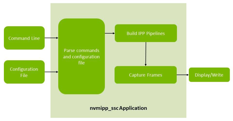
-cf | [filename] | Specifies the configuration file. Co-locate the file with nvmipp_scc. |
-c | [name] | Specifies the parameters set name. In some cases, *.conf files specifies multiple parameter sets. This option identifies the set to use in the `*.conf` file specified with the -cf option. |
Option | Parameter | Description | Default |
-h | N/A | Prints usage and help menu. | N/A |
--ext_sync | [duty_ratio] | Enables external syncrhonization. (AR0231 or OV10635 sensors only.) | 0.25 |
-v | [level] | Logging level = 0 (Errors) 1 (Warnings) 2 (Information) 3 (Debug)If no level is provided, defaults to 3. | 0 |
-lc | N/A | Lists the available configuration parameter sets. | N/A |
-d | [id] | Enables the display. If provided, uses the display with the specified ID. | Display is disabled. If ID is not provided, the sample uses the first display available. |
--aggregate | [n] | Specifies the number of aggregated images. | Default: n = 1 |
-f | [filename] | Writes frames from each sensor to a separate file named from the provided file prefix. | Default: Image writing is disabled. |
-w | [n] | Set display window ID [0-2]. | Default: 0 |
-z | [n] | Set display window depth [0-255]. | Default: 0 |
--show-timestamp | N/A | Shows timestamp information. Requires -v option. | N/A |
Command | Default |
h | Prints the available commands. |
q | Quits the application. |
c | Cycles the sensor image on display. |
Camera Group | Camera Type | Number of Cameras | Command Set |
A | AR0231 RCCB (Module name: SS3322) | 1 | ./nvmipp_ssc -cf drive-px2-a.conf -c dvp-ss3322-rccb-raw12-1920x1208-ab -d 0 --aggregate 1 -w 1 |
4 | ./nvmipp_ssc -cf drive-px2-a.conf -c dvp-ss3322-rccb-raw12-1920x1208-ab -d 0 --aggregate 4 -w 1 | ||
AR0231 RCCB (Module name: SS3323) | 1 | ./nvmipp_ssc -cf drive-px2-a.conf -c dvp-ss3323-rccb-raw12-1920x1208-ab -d 0 --aggregate 1 -w 1 | |
4 | ./nvmipp_ssc -cf drive-px2-a.conf -c dvp-ss3323-rccb-raw12-1920x1208-ab -d 0 --aggregate 4 -w 1 | ||
Continental OV10640 (Module name: SVC210) | 1 | ./nvmipp_ssc -cf drive-px2-a.conf -c dvp-svc210-raw12-1280x1080-ab -d 0 --aggregate 1 -w 1 | |
4 | ./nvmipp_ssc -cf drive-px2-a.conf -c dvp-svc210-raw12-1280x1080-ab -d 0 --aggregate 4 -w 1 | ||
Continental OV10640 (Module name: SVC212) | 1 | ./nvmipp_ssc -cf drive-px2-a.conf -c dvp-svc212-raw12-1280x1080-ab -d 0 --aggregate 1 -w 1 | |
4 | ./nvmipp_ssc -cf drive-px2-a.conf -c dvp-svc212-raw12-1280x1080-ab -d 0 --aggregate 4 -w 1 | ||
B | AR0231 RCCB (Module name: SS3322) | 1 | ./nvmipp_ssc -cf drive-px2-a.conf -c dvp-ss3322-rccb-raw12-1920x1208-ab -d 0 --aggregate 1 -w 1 |
4 | ./nvmipp_ssc -cf drive-px2-a.conf -c dvp-ss3322-rccb-raw12-1920x1208-ab -d 0 --aggregate 4 -w 1 | ||
AR0231 RCCB (Module name: SS3323) | 1 | ./nvmipp_ssc -cf drive-px2-a.conf -c dvp-ss3323-rccb-raw12-1920x1208-ab -d 0 --aggregate 1 -w 1 | |
4 | ./nvmipp_ssc -cf drive-px2-a.conf -c dvp-ss3323-rccb-raw12-1920x1208-ab -d 0 --aggregate 4 -w 1 | ||
Continental OV10640 (Module name: SVC210) | 1 | ./nvmipp_ssc -cf drive-px2-a.conf -c dvp-svc210-raw12-1280x1080-ab -d 0 --aggregate 1 -w 1 | |
4 | ./nvmipp_ssc -cf drive-px2-a.conf -c dvp-svc210-raw12-1280x1080-ab -d 0 --aggregate 4 -w 1 | ||
Continental OV10640 (Module name: SVC212) | 1 | ./nvmipp_ssc -cf drive-px2-a.conf -c dvp-svc212-raw12-1280x1080-ab -d 0 --aggregate 1 -w 1 | |
4 | ./nvmipp_ssc -cf drive-px2-a.conf -c dvp-svc212-raw12-1280x1080-ab -d 0 --aggregate 4 -w 1 | ||
C | AR0231 RCCB (Module name: SS3322) | 1 | ./nvmipp_ssc -cf drive-px2-a.conf -c dvp-ss3322-rccb-raw12-1920x1208-ab -d 0 --aggregate 1 -w 1 |
4 | ./nvmipp_ssc -cf drive-px2-a.conf -c dvp-ss3322-rccb-raw12-1920x1208-ab -d 0 --aggregate 4 -w 1 | ||
AR0231 RCCB (Module name: SS3323) | 1 | ./nvmipp_ssc -cf drive-px2-a.conf -c dvp-ss3323-rccb-raw12-1920x1208-ab -d 0 --aggregate 1 -w 1 | |
4 | ./nvmipp_ssc -cf drive-px2-a.conf -c dvp-ss3323-rccb-raw12-1920x1208-ab -d 0 --aggregate 4 -w 1 | ||
Continental OV10640 (Module name: SVC210) | 1 | ./nvmipp_ssc -cf drive-px2-a.conf -c dvp-svc210-raw12-1280x1080-ab -d 0 --aggregate 1 -w 1 | |
4 | ./nvmipp_ssc -cf drive-px2-a.conf -c dvp-svc210-raw12-1280x1080-ab -d 0 --aggregate 4 -w 1 | ||
Continental OV10640 (Module name: SVC212) | 1 | ./nvmipp_ssc -cf drive-px2-a.conf -c dvp-svc212-raw12-1280x1080-ab -d 0 --aggregate 1 -w 1 | |
4 | ./nvmipp_ssc -cf drive-px2-a.conf -c dvp-svc212-raw12-1280x1080-ab -d 0 --aggregate 4 -w 1 |
Camera Group | Camera Type | Number of Cameras | Command Set |
A | AR0231 RCCB (Module name: SS3322) | 1 | ./nvmipp_ssc -cf drive-px2-b.conf -c dvp-ss3322-rccb-raw12-1920x1208-ab -d 0 --aggregate 1 -w 1 |
4 | ./nvmipp_ssc -cf drive-px2-b.conf -c dvp-ss3322-rccb-raw12-1920x1208-ab -d 0 --aggregate 4 -w 1 | ||
AR0231 RCCB (Module name: SS3323) | 1 | ./nvmipp_ssc -cf drive-px2-b.conf -c dvp-ss3323-rccb-raw12-1920x1208-ab -d 0 --aggregate 1 -w 1 | |
4 | ./nvmipp_ssc -cf drive-px2-b.conf -c dvp-ss3323-rccb-raw12-1920x1208-ab -d 0 --aggregate 4 -w 1 | ||
Continental OV10640 (Module name: SVC210) | 1 | ./nvmipp_ssc -cf drive-px2-b.conf -c dvp-svc210-raw12-1280x1080-ab -d 0 --aggregate 1 -w 1 | |
4 | ./nvmipp_ssc -cf drive-px2-b.conf -c dvp-svc210-raw12-1280x1080-ab -d 0 --aggregate 4 -w 1 | ||
Continental OV10640 (Module name: SVC212) | 1 | ./nvmipp_ssc -cf drive-px2-b.conf -c dvp-svc212-raw12-1280x1080-ab -d 0 --aggregate 1 -w 1 | |
4 | ./nvmipp_ssc -cf drive-px2-b.conf -c dvp-svc212-raw12-1280x1080-ab -d 0 --aggregate 4 -w 1 | ||
B | AR0231 RCCB (Module name: SS3322) | 1 | ./nvmipp_ssc -cf drive-px2-b.conf -c dvp-ss3322-rccb-raw12-1920x1208-ab -d 0 --aggregate 1 -w 1 |
4 | ./nvmipp_ssc -cf drive-px2-b.conf -c dvp-ss3322-rccb-raw12-1920x1208-ab -d 0 --aggregate 4 -w 1 | ||
AR0231 RCCB (Module name: SS3323) | 1 | ./nvmipp_ssc -cf drive-px2-b.conf -c dvp-ss3323-rccb-raw12-1920x1208-ab -d 0 --aggregate 1 -w 1 | |
4 | ./nvmipp_ssc -cf drive-px2-b.conf -c dvp-ss3323-rccb-raw12-1920x1208-ab -d 0 --aggregate 4 -w 1 | ||
Continental OV10640 (Module name: SVC210) | 1 | ./nvmipp_ssc -cf drive-px2-b.conf -c dvp-svc210-raw12-1280x1080-ab -d 0 --aggregate 1 -w 1 | |
4 | ./nvmipp_ssc -cf drive-px2-b.conf -c dvp-svc210-raw12-1280x1080-ab -d 0 --aggregate 4 -w 1 | ||
Continental OV10640 (Module name: SVC212) | 1 | ./nvmipp_ssc -cf drive-px2-b.conf -c dvp-svc212-raw12-1280x1080-ab -d 0 --aggregate 1 -w 1 | |
4 | ./nvmipp_ssc -cf drive-px2-b.conf -c dvp-svc212-raw12-1280x1080-ab -d 0 --aggregate 4 -w 1 | ||
C | AR0231 RCCB (Module name: SS3322) | 1 | ./nvmipp_ssc -cf drive-px2-b.conf -c dvp-ss3322-rccb-raw12-1920x1208-ab -d 0 --aggregate 1 -w 1 |
4 | ./nvmipp_ssc -cf drive-px2-b.conf -c dvp-ss3322-rccb-raw12-1920x1208-ab -d 0 --aggregate 4 -w 1 | ||
AR0231 RCCB (Module name: SS3323) | 1 | ./nvmipp_ssc -cf drive-px2-b.conf -c dvp-ss3323-rccb-raw12-1920x1208-ab -d 0 --aggregate 1 -w 1 | |
4 | ./nvmipp_ssc -cf drive-px2-b.conf -c dvp-ss3323-rccb-raw12-1920x1208-ab -d 0 --aggregate 4 -w 1 | ||
Continental OV10640 (Module name: SVC210) | 1 | ./nvmipp_ssc -cf drive-px2-b.conf -c dvp-svc210-raw12-1280x1080-ab -d 0 --aggregate 1 -w 1 | |
4 | ./nvmipp_ssc -cf drive-px2-b.conf -c dvp-svc210-raw12-1280x1080-ab -d 0 --aggregate 4 -w 1 | ||
Continental OV10640 (Module name: SVC212) | 1 | ./nvmipp_ssc -cf drive-px2-b.conf -c dvp-svc212-raw12-1280x1080-ab -d 0 --aggregate 1 -w 1 | |
4 | ./nvmipp_ssc -cf drive-px2-b.conf -c dvp-svc212-raw12-1280x1080-ab -d 0 --aggregate 4 -w 1 |