IPP YUV (nvmipp_yuv)
The NvMedia nvmipp_yuv sample application demonstrates how to create NvMedia IPP components to build one or more IPP pipelines to process YUV image output.
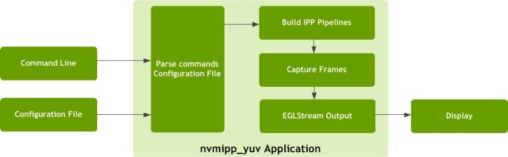
The application builds multiple concurrent IPP pipelines and renders aggregate stream output. The output of IPP is sent through EGL Stream to an OpenGL consumer that applies local tone mapping. It operates by parsing command line arguments and a configuration file.
The application requires you to provide a command line input with:
• A configuration file
• Capture parameter sets
• The number of cameras to aggregate
The configuration file contains multiple capture parameter sets, one of which is used in the command line. The application parses configuration settings and other command line parameters, and builds the IPP pipeline with the required components. It starts the IPP pipeline to keep capturing frames and sends them to the EGL stream output for display.
The following diagram provides an overview of the process.
The NvMedia nvmipp_yuv sample application supports:
• YUV input format YUV422
The NvMedia nvmipp_yuv sample application also supports:
• Provides parameter sets dvp-ov10635-yuv422-1280x800-ab in <drive-px2-autocruise|drive-px2-a|drive-px2-b>.conf
Constructing an IPP Pipeline
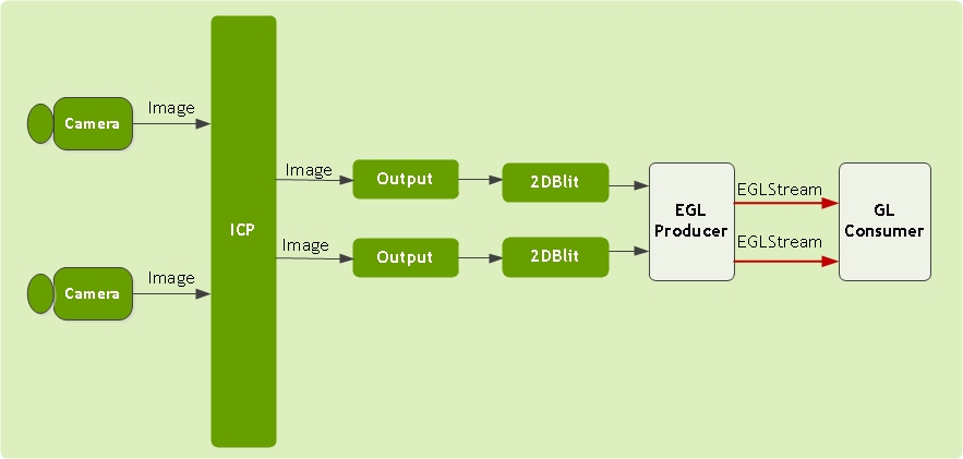
The NvMedia IPP YUV sample application provides an example on how to build IPP pipelines and process YUV data from cameras. The diagram below describes typical IPP pipelines built for processing 2 cameras. One IPP pipeline is needed for each camera. Each IPP YUV pipeline consists of:
• Image Capture Processing (ICP)
• Output
EGL producer and GL consumer are attached to the IPP pipeline output to provide streams for display.
The following diagram shows the system when two IPP pipelines are constructed.
Threads
When only one ICP is created and it is attached to all pipelines, each IPP component except the Output component is an individual thread. Besides IPP threads, three more threads are alive:
• The main thread
• EGL Producer
• The GL Consumer
Main Thread
The main thread:
• Parses command line options
• Constructs IPP pipelines
• Starts EGL Producer and GL Consumer
After IPP pipelines are started, the main thread processes user input in interactive mode. When the user quits, the main thread stops the pipelines, and releases resources.
EGL Producer
The thread of EGL Producer is defined as ipp_GetIPPOutputThreadFunc, which runs in a loop that does the following:
1. Gets an IPP output, NvMediaIPPComponentGetOutput
2. Gets metadata for the current output, NvMediaIPPMetadataGetAddress
3. Posts metadata to EGL Stream, NvMediaEglStreamProducerPostMetaData)
4. Posts the output image to EGL Stream, NvMediaEglStreamProducerPostImage
5. Retrieves one released image from EGL Stream, NvMediaEglStreamProducerGetImage
6. Returns the IPP output, NvMediaIPPComponentReturnOutput
GL Consumer
Similar to EGL Producer, GL Consumer also runs in a loop. It receives images in semi-planar YUV 4:2:0 format through EGL Stream. The local tone mapping's metadata is received for each image and used to generate a three-dimensional table. The GL fragment shader applies local tone mapping by looking up the table through a 3D texture. After rendering is finished, the image is displayed. The consumer also releases one image for each EGL Stream at the end of one iteration.
Configuration Parameters
Each configuration file must start with a list of configuration parameters. These parameters are used by the application to determine the capture settings. The required parameters are:
; Interface: <type>
; Input Format: <format>
; Resolution: <resolution>
; CSI Lanes: <number of lanes>
; I2C Device: <device number>
; Sensor Address: <address>
• Interface—specifies the CSI interface type used
• Input Format—specifies the format the sensor is capturing images.
• Resolution—specifies the resolution the sensor is capturing. This includes embedded lines.
• CSI Lanes—specifies the number of CSI lanes used.
• I2C Device—specifies the ID of the I2C device that is connected to the aggregator. Sensor address specifies the address of the sensor used for I2C.
You can also provide optional configuration parameters:
; Surface Format: <surface format>
; Max9286 Address: <address>
• Surface Format—specifies the CSI surface format. If this is not provided, the application chooses a default surface format based on the input format.
• Max9286 Address—provides additional debug information by dumping the registers of the aggregator.
Following is an example configuration for the p2360 board:
; Interface: csi-ab
; Input Format: yuv422
; Resolution: 1280x1084
; CSI Lanes: 4
; I2C Device: 2
; Sensor Address: 0x30
; Max9286 Address: 0x48 Running the sample application
Example Commands
This example uses CSI AB interface connected with four OV10635 cameras for Tegra A, each of which outputs 1280 x 800 YUV data.
• Enter the following command:
./x11/nvmipp_yuv -cf drive-px2-a.conf -c dvp-ov10635-yuv422-1280x800-ab -d 0 --aggregate 4
1. Start screen (ipp applications utilize screen windowing system).
2. Go to the following directory:
/drive-t186ref-linux/samples/nvmedia/ipp_yuv
3. Enter the following command:
./x11/nvmipp_yuv -cf drive-px2-a.conf -c dvp-ov10635-yuv422-1280x800-ab -d 0 --aggregate 4
Parameter Map on DRIVE PX 2 (P3407)
The following table show the parameters map to the Camera CSI physical group on the DRIVE PX 2 (P2379) for the supported camera types.
Camera Group | Camera Type | Number of Cameras | Command Set |
A | OV10635 | 1 | ./x11/nvmipp_yuv -cf drive-px2-autocruise.conf -c dvp-ov10635-yuv422-1280x800-ab -d 0 --aggregate 1 |
4 | ./x11/nvmipp_yuv -cf drive-px2-autocruise.conf -c dvp-ov10635-yuv422-1280x800-ab -d 0 --aggregate 4 |
B | OV10635 | 1 | ./x11/nvmipp_yuv -cf drive-px2-autocruise.conf -c dvp-ov10635-yuv422-1280x800-cd -d 0 --aggregate 1 |
4 | ./x11/nvmipp_yuv -cf drive-px2-autocruise.conf -c dvp-ov10635-yuv422-1280x800-cd -d 0 --aggregate 4 |
Parameter Map on DRIVE PX 2 (P2379) Tegra A
The following table show the parameters map to the Camera CSI physical group on the DRIVE PX 2 (P2379) for Tegra A for the supported camera types.
Camera Group | Camera Type | Number of Cameras | Command Set |
A | OV10635 | 1 | ./x11/nvmipp_yuv -cf drive-px2-a.conf -c dvp-ov10635-yuv422-1280x800-ab -d 0 --aggregate 1 |
4 | ./x11/nvmipp_yuv -cf drive-px2-a.conf -c dvp-ov10635-yuv422-1280x800-ab -d 0 --aggregate 4 |
B | OV10635 | 1 | ./x11/nvmipp_yuv -cf drive-px2-a.conf -c dvp-ov10635-yuv422-1280x800-cd -d 0 --aggregate 1 |
4 | ./x11/nvmipp_yuv -cf drive-px2-a.conf -c dvp-ov10635-yuv422-1280x800-cd -d 0 --aggregate 4 |
C | OV10635 | 1 | ./x11/nvmipp_yuv -cf drive-px2-a.conf -c dvp-ov10635-yuv422-1280x800-ef -d 0 --aggregate 1 |
4 | ./x11/nvmipp_yuv -cf drive-px2-a.conf -c dvp-ov10635-yuv422-1280x800-ef -d 0 --aggregate 4 |
Parameter Map on DRIVE PX 2 (P2379) Tegra B
The following table show the parameters map to the Camera CSI physical group on the DRIVE PX 2 (P2379) for Tegra B for the supported camera types.
Camera Group | Camera Type | Number of Cameras | Command Set |
A | OV10635 | 1 | ./x11/nvmipp_yuv -cf drive-px2-b.conf -c dvp-ov10635-yuv422-1280x800-ab -d 0 --aggregate 1 |
4 | ./x11/nvmipp_yuv -cf drive-px2-b.conf -c dvp-ov10635-yuv422-1280x800-ab -d 0 --aggregate 4 |
B | OV10635 | 1 | ./x11/nvmipp_yuv -cf drive-px2-b.conf -c dvp-ov10635-yuv422-1280x800-cd -d 0 --aggregate 1 |
4 | ./x11/nvmipp_yuv -cf drive-px2-b.conf -c dvp-ov10635-yuv422-1280x800-cd -d 0 --aggregate 4 |
C | OV10635 | 1 | ./x11/nvmipp_yuv -cf drive-px2-b.conf -c dvp-ov10635-yuv422-1280x800-ef -d 0 --aggregate 1 |
4 | ./x11/nvmipp_yuv -cf drive-px2-b.conf -c dvp-ov10635-yuv422-1280x800-ef -d 0 --aggregate 4 |
Command Options
The following command line shows the command syntax.
./x11/nvmipp_yuv -cf [filename] -c [name] --aggregate [n] [options]
Required Commands
The following table describes the required command line arguments.
Option | Parameter | Description |
-cf | [filename] | Specifies the configuration file. |
-c | [name] | Specifies the parameter set name. Each *.conf file specifies multiple parameter sets. This option identifies the set to use in the *.conf file specified with the -cf option. |
--aggregate | [n] | Specifies the number of aggregated images. |
--slave | N/A | Specifies that the application is running with a slave aggregator. |
Optional Commands
The following table describes optional command line arguments.
Option | Parameter | Description | Default Settings |
-h | N/A | Prints usage and help menu. | N/A |
--ext_sync | [duty_ratio] | Enables external synchronization. (AR0231 or OV10635 sensors only.) | 0.25 |
-v | [level] | Logging level: • 0 (Errors) • 1 (Warnings) • 2 (Information) • 3 (Debug) | If no level is provided, defaults to 3. If option is not provided, defaults to 0. |
-lps | N/A | Lists the available configuration parameter sets. | N/A |
--mailbox | N/A | Make nvmipp_yuv manage frames in Mailbox Mode mode. Otherwise, they are managed in FIFO Mode mode. | N/A |
--show-timestamp | N/A | Shows the timestamp information. Use with -v option. | N/A |
--show-metadata | N/A | Shows the metadata information. Use with -v option. | N/A |
-d | [id] | Enables the display. If provided, uses the display with the specified ID. | Default: Display is disabled. If the ID is not provided, the sample uses the first display available. |
--cam_enable | [n] | Enables or disables camera[3210]; enable:1, disable:0 | Default: n=0001 |
--cam_mask | [n] | Masks or unmasks camera[3210]; 0, 1, 2, or 3 | Default: n=0000 |
--csi_outmap | [n] | Sets csi out order for camera[3210]; 0, 1, 2, or 3 | Default: n=3210 |
Troubleshooting
Users of this application have encountered the following issues.
Video Link Errors
Several situations can cause generic video link errors.
Error
When entering the test command for DRIVE PX 2:
./x11/nvmipp_yuv -cf drive-px2-a.conf -c dvp_ov10635_yuv422_1280x800-ab --aggregate 1
The error messages are as follows:
nvmedia: ERROR: SetupVideoLink: Image sensor(0) device is not present
nvmedia: ERROR: Init: Failed to setup video link
nvmedia: ERROR: IPPInit: Failed to initialize ISC devices
nvmedia: ERROR: IPPInit: Failed
Possible causes include:
• One or more cameras are not connected to the right CSI port or not started at port numbered 0. The number of cameras connected must match the number specified in the --aggregate option.
• The type of sensor connected and the configuration parameter specified in the command line conflict.
• One of the cameras failed to start or is not functioning.