nvmipp_capture_encode
The ipp_capture_encode application demonstrates how to use the NvMedia IPP framework to process raw image input from one or more cameras and subsequently encode the IPP output using the NvMedia IEP API. The encoded bit stream is eventually written to a file.
Each instance of the application can exercise up to four cameras on a camera group port. To exercise more than four cameras or cameras on different camera group ports, multiple instances of the application are required.
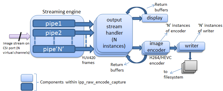
Each camera input is handled by an IPP pipeline, an encoder, and a file writer component, working in tandem. Additionally, the output of the first pipeline can be redirected to a display. The following diagram shows the different modules of the application.
The application has four major modules:
• The Streaming Engine internally uses the NvMedia IPP framework to provide capture, ISP processing, algorithm control and sensor control functionality.
• The Output Stream Handler manages the data flow between the streaming engine (producer) and the image encoder or display (consumers).
• The Image Encoder internally uses the NvMediaIEP to encode uncompressed frames.
• The File Writer writes compressed frames to the file system.
Streaming Engine
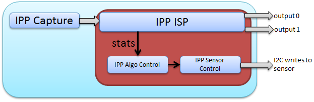
The streaming engine uses the NvMedia IPP framework to present a consolidated view of the capture, ISP processing, algorithm control functionality and sensor control functionality for multiple camera inputs.
Multiple camera inputs can be aggregated into a CSI port. A pipe is created for each camera input. The pipe consolidates the camera capture, ISP processing, algorithm control and sensor control functionality for the corresponding camera input. An application pipe and the different IPP components that it instantiates is shown in the following diagram.
Output Ports
In context of the application, each streaming engine pipe can generate up to two outputs. These outputs can be channeled to different consumers of different latencies. The reference counting is managed internally by the IPP. If two outputs are enabled for a pipe, then it signifies that the pipe will generate two parallel output streams for the same camera. In context of the application, pipe0 will have up to two output ports feeding into encoder and display. All other pipes have only one output port.
Algorithm Processing and Sensor Control
Each of the streaming engine pipes internally use the IPP algorithm and sensor control modules to facilitate real time processing of statistics generated by the ISP.
Output Stream Handler
In context of the application, each pipe of the streaming engine can generate up to two outputs. The output stream handler module ensures that two consumers can consume the frames generated by a streaming engine pipe in a safe manner. There are as many instances of the output stream handler as there are instances of pipes in the streaming engine. Each instance of the output stream handler is bound to the corresponding pipe of the streaming engine by way of pipe number.
In context of the application, the consumers are the display and the encoder->writer. They have different processing latencies and the output stream handler makes no assumptions about the time each consumer takes to process a frame.
Each instance of the output stream handler has as many execution threads as outputs from the corresponding streaming engine pipe. In its execution context, the output stream handler ‘waits’ on availability of frames on the streaming engine pipe and if they are available, sends them out to the consumer queues.
Image Encoder
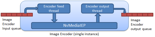
The Image Encoder module uses the NvMedia IEP API. The streaming engine has the capability to generate multiple image streams (through multiple pipes). The application instantiates one image encoder instance each for each of the active pipes. Each instance of the encoder is bound to an instance of the output stream handler, which in turn is bound to a streaming engine pipe. The encoder uses the NvMedia IEP APIs for exercising the underlying encoder hardware. Figure 3 shows the Image Encoder module with its input and output interfaces and the NvMedia IEP component.
Each instance of the image encoder module instantiates two threads. The first thread (encoder feed thread) extracts uncompressed frame from its input queue and feeds it to the NvMedia IEP encoder. The second thread (encoder output thread) extracts encoded frames from the encoder and pushes them to writer feed queue.
File Writer
The file writer component is the consumer of the encoded streams coming from the image encoder. The application instantiates one instance of the file writer each for each of the active streaming engine pipes. Each instance of the file writer is bound to an instance of the encoder, which in turn is bound to an output stream handler and streaming engine pipe. Each instance of the file writer implements an execution thread. The thread extracts encoded frame buffer from the writer feed queue and writes it onto an output file.
Command Line Options
The following shows the command syntax.
./nvmipp_capture_encode [options]
The following table describes the required command line arguments.
Option | Parameter | Description |
-w | [n] | Sets display window ID [0-2] |
-z | [n] | Sets display window depth [0-255] |
-p | [position] | Window position. Default: Full screen size. |
--ext_sync | [n] | Enables the external synchronization with <n> duty ratio; 0.0 < n < 1.0. If n is out of the range, set 0.25 to the duty ratio by default. If this option is not set, the synchronization will be handled by the aggregator |
--skip_initial_frames | [n] | Specifies the number of initial frames to skip from encoding. Useful for ignoring AE/AWB convergence period. Default is 0. |
-cf | [capture_file] | Specifies the capture configuration file used. Default: configs/capture.conf. |
-c | [config_set] | Specifies the capture configuration set name to be used. Defaults to the first configuration set with in the capture configuration file. |
--aggregate | [1-4] | Specify the number of frames aggregated. Optional if streaming with one camera, otherwise required. Default is 1. |
--vc_enable | - | If used, multiple camera inputs are aggregated using different CSI virtual channels. By default, virtual channels are not used. |
--cam_enable | [<camera_bitfield>] | Enables or disables cameras, where each bit represents a camera in [3210] order. The leftmost bit controls camera 3 and the rightmost bit, camera 0. Bit settings for each camera are: Enable: 1 Disable: 0 Video is not available from a disabled camera. |
--cam_mask | [<camera_bitfield>] | Masks or unmasks cameras, where each bit represents a camera in [3210] order. All cameras cannot be simultaneously masked; [1111] is not allowed. Bit settings for each camera are: Mask: 1 Unmask: 0 |
--csi_outmap | - | Sets the CSI output order for the cameras. The <a, b, c, d> order can be 0, 1, 2, or 3 in any order. Each number must only be used once. Default is 3, 2, 1, 0. |
--plugin | - | Specifies to use the sample IPP plugins (provided as part of the tests) for control algorithm components. |
--nvplugin | - | Specifies to use NvMedia IPP plugins for control algorithm components. |
Encode-related inputs |
-e | - | Specifies the encoder type. Valid values are: 0: H.264 encode
1: H.265 encode |
-t | - | Specifies the encoding preset: 0: (LOW_LATENCY_CONSTANT_BITRATE)
1: (CONSTANT_QUALITY)
2: (MAIN_QUALITY_CONSTANT_BITRATE) Default is 0. |
-qpi | - | Specify to override the default QP value of I frame for CONSTANT_QUALITY preset. Default is 20. |
-qpp | - | Specify to override the default QP value of P frame for CONSTANT_QUALITY preset. Default is 23. |
--lossless | - | Specify to use lossless compression. Applicable only for H.265 encoding. Default: Lossless encoding inactive. |
--cbr | - | Specify to override the default average bit rate for LOW_LATENCY_CONSTANT_BITRATE and MAIN_QUALITY_CONSTANT_BITRATE presets. For example, --cbr 8 overrides the average bit rate to 8 Mbps. Default is 2 Mbps. |
-f | - | Specifies the frame rate in floating point precision e.g. 30.0. Default is 30.0. |
-r | - | Set this to 1 for limited-RGB (16-235) input. Default: Limited RGB not enabled. |
Miscellaneous Inputs |
-lps | - | Prints the config sets available in the capture configuration file specified by -cf option |
-o | - | Specifies the output file name (with path). If multiple pipes are active, _n is appended to the filename, where n is the pipe number. |
--slave | - | Specifies that the application be run on a slave Tegra proccesor. |
-v | - | Specifies logging level. 0: Errors (Default)
1: Warnings
2: Info
3: Debug |
-d | - | Specifies the display ID. If specified, only the first pipe output is directed to the display. |
-h | - | Prints usage information. |
The application can provide --plugin or --nvplugin, but not both. The --cam_enable and --aggregate options are complementary in nature. Either may be used, but not both.
Tegra A Examples
The following are examples of Tegra A use cases.
Use Case
4 AR0231 on camera group A with 4 cameras using virtual channel and H.264 encode. The encode preset is LOW_LATENCY_CONSTANT_BITRATE. The display is on port 0, using nvplugin.
Command
./nvmipp_capture_encode -cf drive-px2-a.conf -c dvp-ar0231-raw12-1920x1208-ab -e 0 -t 0 -o output_AB.h264 -d 0 --aggregate 4 --vc_enable --nvplugin
Use Case
4 Continental OV10640 cameras on camera group B, with 4 cameras using virtual channel and H.265 encode. The encode preset is HIGH_QUALITY_CONSTANT_BITRATE. No display is used. Sample plugin is used.
Command
./nvmipp_capture_encode -cf drive-px2-a.conf -c dvp-svc210-raw12-1280x1080-cd -e 1 -t 2 -o output_CD.h265 --aggregate 4 --vc_enable --plugin
Use Case
A Maxim OV10640 on camera group C, with 4 cameras using virtual channel and H.265 encode. The encode preset is CONSTANT_QUALITY. No display is used. Nvplugin is used.
Command
./nvmipp_capture_encode -cf drive-px2-a.conf -c dvp-ov10640-raw12-1280x1080-ef -e 1 -t 1 -o output_EF.h265 --aggregate 4 --vc_enable --nvplugin
Tegra B Examples
The following are examples of Tegra B use cases.
Use Case
An AR0231 on camera group A, with 4 cameras using virtual channel and H.264 encode. The encode preset is LOW_LATENCY_CONSTANT_BITRATE on display port 0 using nvplugin.
Command
./nvmipp_capture_encode -cf drive-px2-b.conf -c dvp-ar0231-raw12-1920x1208-ab -e 0 -t 0 -o output_AB.h264 -d 0 --aggregate 4 --vc_enable --nvplugin
Use Case
4 Continental OV10640 cameras on camera group B, with 4 cameras using virtual channel and H.265 encode. The encode preset is HIGH_QUALITY_CONSTANT_BITRATE. No display is used. Sample plugin is used.
Command
./nvmipp_capture_encode -cf drive-px2-b.conf -c dvp-svc210-raw12-1280x1080-cd -e 1 -t 2 -o output_CD.h265 --aggregate 4 --vc_enable --plugin
Use Case
A Maxim OV10640 on camera group C, with 4 cameras using virtual channel and H.265 encode. The encode preset is CONSTANT_QUALITY. No display is used. Nvplugin is used.
Command
./nvmipp_capture_encode -cf drive-px2-b.conf -c dvp-ov10640-raw12-1280x1080-ef -e 1 -t 1 -o output_EF.h265 --aggregate 4 --vc_enable --nvplugin
Terminating the Application
Press q on the console to terminate a launched application.
Troubleshooting Common Error Messages
The following are troubleshooting tips for common error messages.
Video Link Errors
The error messages are as follows:
nvmedia: ERROR: SetupVideoLink: Can't detect config link(2)
nvmedia: ERROR: Init: Failed to setup video link
nvmedia: ERROR: IPPInit: Failed to initialize ISC devices
nvmedia: ERROR: IPPInit: Failed
nvmedia: ERROR: main: Error in IPPInit
Troubleshooting
1. Check the camera connections. They must be mounted sequentially starting from 0.
2. Check that the number of cameras specified in the command line (e.g., --aggregate 4) is correct.
3. Check that the camera type specified through the config set matches the actual cameras mounted.
ICP Drop
They manifest as warnings only if the application is launched with at least logging level 1 (i.e., --v 1). The warnings are as follows:
nvmedia: WARNING: [CameraId: 2 Frame: 28 CaptureTimestamp: 1167906699] - ICP DROP
nvmedia: WARNING: [CameraId: 3 Frame: 28 CaptureTimestamp: 1167906707] - ICP DROP
nvmedia: WARNING: [CameraId: 0 Frame: 29 CaptureTimestamp: 1167940090] - ICP DROP
nvmedia: WARNING: [CameraId: 1 Frame: 33 CaptureTimestamp: 1168073765] - ICP DROP
Each instance of the application works with a maximum of 4 cameras on a given camera group. If multiple instances of the application are launched, exercising more than 4 cameras, then these warnings may appear, indicating that the system is running at its maximum limit. Another possible cause of these messages is when the display rate is slower than the capture rate (e.g., displaying on a 4K monitor with display rate of 30Hz with capture running at 36fps).