NVIDIA DRIVE OS 5.1 Linux Developer Guide 5.1.0.2 Release |
NVIDIA DRIVE OS 5.1 Linux Developer Guide 5.1.0.2 Release |
Note: | This section applies to a board on a bench. For information on the full Hyperion hardware setup, see the NVIDIA DRIVE AGX Developer Kit Hardware Quick Start Guide available at https://developer.nvidia.com/drive/drive-hyperion. |
Item Number | Label | Component and Description |
1 | DRIVE Main | 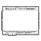 NVIDIA DRIVE Development Platform Xavier |
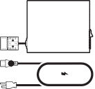
2 | System Power | 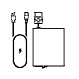 Power supply, power adapter and US power cord |
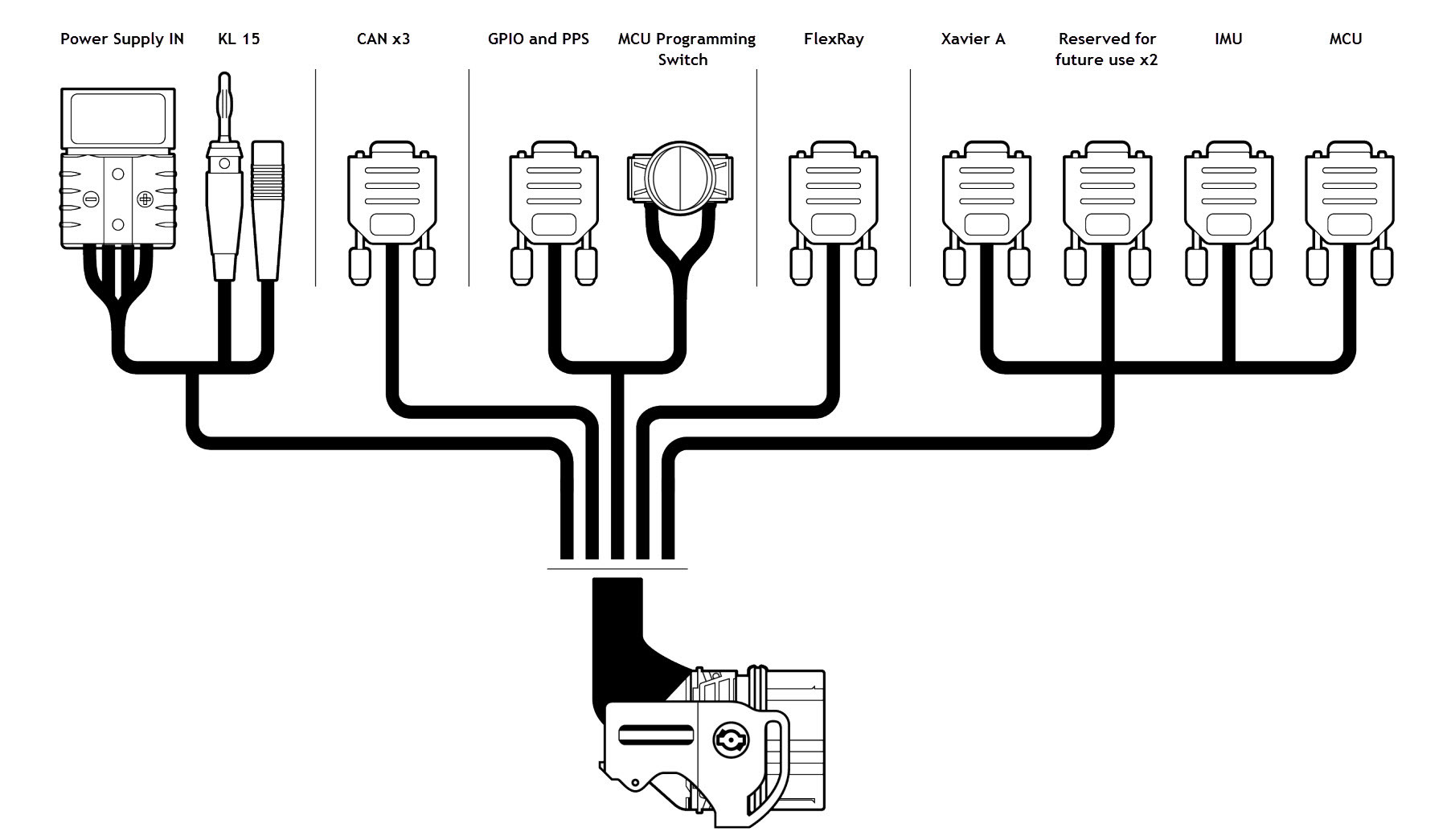
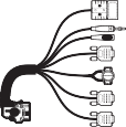
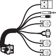
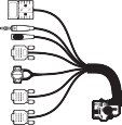
3 | Vehicle Harness | 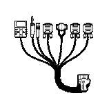 48-pin Vehicle cable harness |
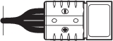
4 | RTC Module † | 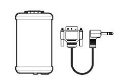 Real-time clock module and PPS cable † |
5 | ACC Power | 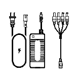 Power adapter for accessories |
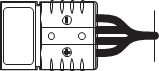
6 | Ethernet | 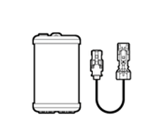 Dual GbE dongle and HSD cable |
7 | USB Hub | 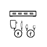 USB 3.0 hub |
8 | USB Type A to Type A Cable | 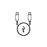 USB 2.0 Type A to Type A cable |
9 | Camera Breakout | 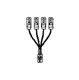 Quad camera breakout cable |
10 | Camera † | 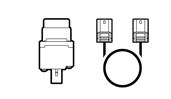 Sekonix 2MP RCCB AR231 60 FOV GMSL camera and Fakra coax cable † |
† These items may NOT be included in the early access kits. • Some of the cables in the kit may not EXACTLY match the images shown. For example, the HSD cable for the Dual GbE Dongle may be slightly different. • Additionally, to ensure correct connections, examine the Real-time Clock Module and the Dual GbE Dongle to identify the differences in these components as shown. | ||
Component | Description |
HDMI display and cable | HDMI display monitor and associated cable to display system output. |
Keyboard | Required to interface with the system. |
Mouse | Required to navigate the system. |
The keyboard is required to use the DriveWorks samples. The mouse is useful for development purposes. A duplicate set of these items are required to operate Xavier B. | |
Component | Description |
Linux host system | Required for cross-compiling, flashing, and access to the console. |
Ethernet cable | Required for internet access. |
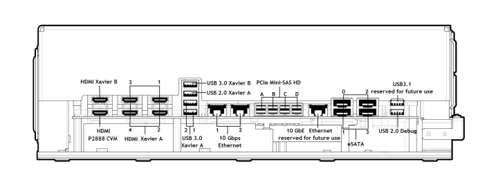
Note: | Use the USB 2.0 Debug port to connect to the Linux host system to: • Flash the firmware • Enable console accesss to: • Xavier A • Xavier B • P2888 CVM • Microcontroller (MCU) |
 |  |  |  |  |
 |  |  |  |  |
Note: | The keyboard is needed to interact with the DriveWorks samples. The mouse is needed for performing development on the platform. The platform is designed as an embedded platform NOT as a development system. Consequently, a desktop is NOT provided at bootup. |
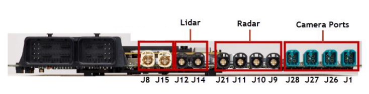
Connector | Lidar Unit |
Link 1&2, Adaptor Ch A | Left side of Velodyne 32 unit |
Link 3&4, Adaptor Ch B | Right side of Velodyne 32 unit |
Link 3&4, Adaptor Ch A | Empty (for desktop-only internet access) |
Link 3&4: Adaptor Ch B | IBEO LUX4L unit (Optional) |
By default, the Lidar IP address is 192.168.1.<xxx>. | |
Connector | IP Address | Location on Vehicle |
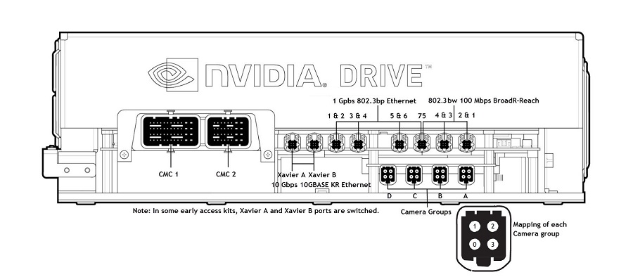
100 Mb - Link 1 2 & 1: A | 10.1.1.20 | FCS - front center under bumper |
100 Mb - Link 2 2 & 1: B | 10.1.1.21 | Front left corner under bumper |
100 Mb - Link 3 4 & 3: A | 10.1.1.22 | Front right corner under bumper |
100 Mb - Link 4 4 & 3: B | 10.1.1.23 | Left rear corner under bumper |
100 Mb - Link 5 5 7: B | 10.1.1.24 | Right rear corner under bumper |
1G - Link 7 5 7: A | 10.1.1.25 | RCS - rear center under bumper |
1G - Link 6 5 & 6: A | 10.1.1.26 | FLX - front left cross traffic under bumper |
1G - Link 5 5 & 6: B | 10.1.1.27 | FRX - front right cross traffic under bumper |
Pin Number | Connector Group D | Connector Group C | Connector Group B | Connector Group A | |
 Camera Port Pins | 0 | Empty | Empty | Front center roof rack 120 | Front center roof rack 60 |
1 | Empty | Empty | Roof rack left A - pillar facing forward 120 | Rear center roof rack 60 | |
2 | Empty | Empty | Roof rack right A - pillar facing forward 120 | Left A - pillar on roof rack rear facing 120 | |
3 | Driver facing 55 | Empty | Empty | Right A - pillar on roof rack rear facing 120 |