Recovery Mechanism
There are many bootloaders involved in boot such as MB1, MB2, QB, PL, and OSL.. Each of them loads several firmware components, such as boot images, partition images and other firmware. On rare occassions, bootloaders may fail to load any of these components due to the following reasons:
• Image is corrupt
For every firmware component, hash validation or signature authentication is performed. If validation or authentication fails, the system declares that the image is corrupt.
• Device read failure
Over the lifetime of the system, device read can fail due to any hardware issue and return an error.
These failures result in boot process failure. This topic describes a recovery mechanism that Tegra system will take when such failure occurs.
Introduction to Boot-Chain
Tegra system maintains a redundant copy of all firmware components that are loaded during system boot process. Redundant components could be identical to the primary ones. However, for a smooth recovery mechanism, the followings should be considered:
• Some of the firmware components have dependencies on each other.
BPMP FW and kernel are dependent on each other. If BPMP FW version and kernel version are not functionally compatible, system may work abnormally.
• Firmware updating process may fail before completion.
Power outages can happen. Due to power outage during firmware update, BPMP FW can be updated with the latest version, but kernel could retain the outdated version. This could result in a malfunctioning system.
As a result, redundant copies are another set of all firmware components that are functionally compatible with each other. This set of firmware components is called Boot Chain. All primary firmware components are in one boot chain and all redundant firmware components are in another boot chain.
Recovery mechanism maintains two boot chains:
• Boot Chain A
• Boot Chain B
At any given time, only one of the boot chains are active. Throughout this document, the active chain will be called Active Boot Chain, and the other bootchainwill be called Inactive Boot Chain.
Boot Chain in Parker SoC based platform
MB1 is the root of boot chain, that is, MB1 is the first bootloader utilizing boot chain.
System includes two identical MB1 image. However, since BootROM has no concept of boot chain, MB1 image does not belong to any boot chain. This poses a limitation that MB1 should always remain compatible with both of boot chain firmware.
Boot Chain in Xavier SoC base platform
BootROM is the root of boot chian, i.e, MB1 is part of the boot chain.
BootROM will select initial active boot chain based on the configuration in BR BCT.
Overview of Chaining Approach
During normal operation, all the bootloaders will load firmware components in active boot chain. If system cannot continue to boot this chain, it will reset to boot the other boot chain.
• Root of boot chain selects an initial Active Boot Chain.
For Parker SoC based platform, MB1 is the root of boot chain.
For Xavier SoC based platform, BootROM is the root of boot chain.
• Every bootloader must load firmware components from Active Boot Chain.
Bootloaders are BootROM, MB1, MB2, Quickboot, and Hypervisor (Partition Loader and OS Loader).
• If a bootloader fails to load a firmware component, system switches Active Boot Chain and Inactive Boot Chain and reset.
Advantages of Chaining Approach
• Chaining approach handles the case of partial update, so the system is always bootable.
• Each chain can be updated independently (except for ratchet update case).
For Parker Soc based platforms, recovery images cannot be updated without updating Primary images.
• Issue of incompatibility between firmware components never occurs.
Side Effect of Chaining Approach
Only two corrupted firmware components could cause an unusable system. For example, if BPMP FW in Active Boot Chain is corrupted and kernel image in Inactive Boot Chain is corrupted, system is unable to boot any of the boot chains and will never boot.
Components not in Boot-Chain
Some of the firmware components are not included in any boot chain due to the nature of the components or BootROM limitation. For those components, multiple copies exist in the system. Bootloader will find a valid one among multiple copies.
Boot Rom BCT (BR BCT) is used to select active boot chain and Global Partition Table defines images belong to each boot chain. Therefore, those components cannot belong to the boot chain.
For Parker SoC based platforms, MB1 is another component not in boot chain. MB1 is excluded due to BootROM limitation.
Recovery Flow Implementation Details
The topics in this section describes the recovery flow implementation details for each bootloader.
Parker SoC based Platform
The topics in this section discuss the key implementation details for recovery flow of Parker SoC based platform.
Scratch Register
PMC Scratch register SCRATCH_99 of Tegra holds the boot chain type. This register is referenced as SCRATCHr henceforth in this document.
Possible assignments of this register are as follows:
• SCRATCHr = 0xdeadbeef implies Boot Chain B.
• Any other value in this register implies Boot Chain A (recommended value is 0).
The contents of this register are retained across soft reboot.
This register is set in the following cases:
• When user wants to boot a particular boot chain, he can set one of the above mentioned values in the scratch register and issue system reboot.
• When any bootloader finds corruption, it will update this register with desired value and will issue system reboot to enforce the system to boot that particular boot chain.
• On normal cold boot, MB1 will clear SCRATCHr register and read the marker value from BR BCT to select active boot chain. Maker can be 0 (Boot Chain A) or 0xDEADBEEF (Boot Chain B).
The contents of this register are read in following cases:
• At any stage during boot, a bootloader reads this register and interprets the active boot chain based on its value as explained above. Once the firmware determines the active boot chain, it loads the next stage firmware images of that chain.
• Before starting system update, the update tool can read this value to determine whether the system has booted the desired boot chain.
All bootloaders, except hypervisor, have read and write permission for the scratch register. For hypervisor, note the following access permissions.
• Read Access
Partition Loader (PL) and OS Loader (OSL) of each guest have read access to this register. With this privilege, they can determine the boot chain type by reading the value of this register directly. Monitor server also has read access to this register.
• Write Access
Only Monitor server has write access to this register. PL/OSL/Guest OS do not have write access to this register.
BootROM recovery flow
BootROM loads Boot ROM BCT and MB1.
Loading Boot ROM BCT (BR BCT)
• There is single partition for storing BR BCT.
• This partition is shared by both Boot Chains and it contains multiple copies of BR BCT. All copies are identical.
• All BR BCT copies are appended to create a blob and this blob is written at the start of zeroth sector of boot device.
• Boot ROM will handle recovery of BR BCT. If one copy of BR BCT is found to be corrupt, it will try with the next one until it finds a valid copy. Boot ROM scans for a maximum of 64 copies of BR BCT. If no valid BR BCT is found, then boot ROM will give up and reset to RCM mode.
• At the time of system update, each copy of BR BCT is updated to new version so that they all are at same version.
Loading MB1
• Two identical MB1 image is stored in the boot device.
• When boot ROM finds that primary MB1 image is corrupt, it loads the recovery MB1 image and continues to boot the system.
• At the time of MB1 update, both primary and recovery partitions of MB1 must be updated.
Selection of Boot Chain by MB1
MB1 is the root of boot chain. Based on following conditions, it selects active boot chain:
• If reset reason is not soft reset, then it reads the Boot Chain Marker in BR BCT, fill it in scratch register SRATCHr and selects boot chain.
• If reset reason is soft reset, then boot chain type are as per value set in SCRATCHr register.
Selection of Boot Chain by Loader FW
Each bootloader, except BootROM and MB1, will check contents of SCRATCHr register.
• If SCRATCHr = 0xdeadbeef, it loads the next stage firmware components in Boot Chain B.
• For any other value, it loads the next stage firmware components in Boot Chain A.
Recovery Mechanism Triggered by Loader FW
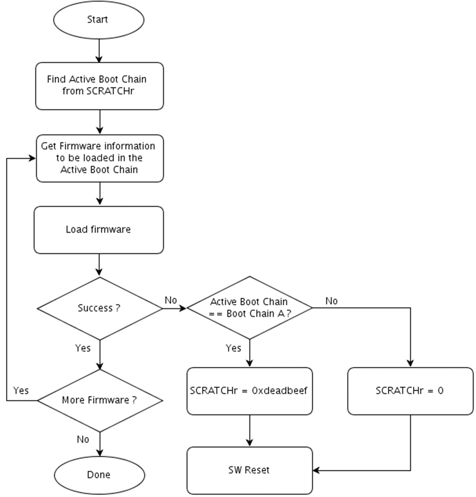
During the boot process, when any bootloader, except BootROM, detects a corruption in the next stage firmware to be loaded, it triggers the recovery mechanism. This is with an exception of global partition table load.
• Try to load next stage firmware in active boot chain.
• If it is loaded successfully, continue to boot.
• Otherwise, recovery mechanism should be triggered.
• If active boot chain is Boot Chain A (SCRATCHr != 0xdeadbeef), then set SCRATCHr = 0xdeadbeef and issue reboot so that system will boot Boot Chain B on reboot.
• If active boot chain is Boot Chain B (SCRATCHr = 0xdeadbeef), then set SCRATCHr = 0 and issue reboot so that system will boot Boot Chain A on reboot.
The following flow chart explains this flow:
Partition Layout
Partition layouts on flash are organized to support recovery mechanism.
• For each partition other than BR BCT, there are two sub-partitions: Boot Chain A and Boot Chain B.
• For BR BCT, there is a single common partition. This partition will contain multiple copies of BR BCT residing at the beginning of boot device.
• For first level partition table (PT) or global partition table, there is a single partition containing multiple copies of PT.
Xavier SoC based platform
The topics in this section discuss the key implementation details for recovery flow for Xavier SoC based platform.
Data Types for Recovery
Data Types used for Recovery mechanism includes scratch register, BootROM BCT, and soft fuses. This section will explain each data types in detail.
Scratch Register
PMC Scratch register SCRATCH_99 of Tegra holds the Active Boot Chain and the Invalid Chain field. This register is referenced as SCRATCHr henceforth in this document.
Register Bit Definitions:
Bit | Default Value | Description |
31:2 | 0 | RSVD: Reserved. The value should not be modified. |
1 | 0 | INVALID_CHAIN: When set to one, Inactive Chain is corrupted. When cleared to zero, no corrupted chain is detected. |
0 | X | ACTIVE _BOOT_CHAIN: When cleared to zero, Active Boot Chain is 0 or Boot Chain A. When set to one, Active Boot Chain is 1 or Boot Chain B. |
The contents of this register are retained across soft reboot.
This register is written in the following cases:
• When user wants to boot a particular boot chain, the usert writes the boot chain in the scratch register and issues system reboot.
• When any bootloader finds corruption, it will update this register with INVALID_CHAIN bit set and a new Active Boot Chain.
The contents of this register are read in following cases:
• At any stage during boot, a bootloader reads this register to find active boot chain. Once the firmware determines the active boot chain, it loads the next stage firmware images in the chain.
• Before starting system update, the update tool can read this value to determine whether the system has booted the desired boot chain.
All bootloaders, except hypervisor, have read and write permissions for the scratch register. For hypervisor, note the following access permissions for the scratch register.
• Read Access
Partition Loader (PL) and OS Loader (OSL) of each guest have read access to this register. Monitor server also has read access to this register.
• Write Access
Only Monitor server has write access to this register. PL/OSL/Guest OS do not have write access to this register.
• BootROM BCT
BootROM BCT includes the following data types to select primary boot chain.
NonGPIOSelectBootChain
Indicates primary Boot Chain when GPIO selection is not enabled.
• 0 is for Boot Chain A and 1 is for Boot Chain B.
GPIOSelectBootChain
Enable or disable GPIO Selection of Boot Chain.
• 0 is to disable GPIO Selection and to use Boot Chain selected by NonGPIOSelectBootChain.
• 1 is to enable GPIO Selection and to use Boot Chain selected by GPIO input.
When enabled, GPIOConfigAddressBootChain and GPIOPadctlAddressBootChain values are used to configure GPIO and read input from the GPIO.
GPIOConfigAddressBootChain
GPIO configuration address that will be used to select Boot Chain.
GPIOPadctlAddressBootChain
GPIO Pad control address that will be used to select Boot Chain.
Soft Fuse
Soft fuses are used to determine the recovery action to take when a bootloader fails to load a firmware component.
SwitchBootChain
The bootloader switches boot chain, only if this value is set.
MB1 will overwrite this value to zero when GPIO selection is enabled.
ResetToRecovery
This information is used when system doesn’t switch boot chain.
When set to one, system will reboot to forced recovery mode.
When cleared to zero, system will hang.
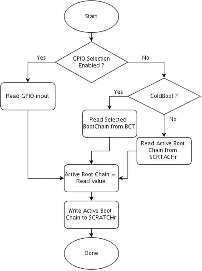
Selection of Boot Chain by BootROM
BootROM, the root of boot chain, is responsible for selecting Active Boot Chain after power up. It will follow the following selection sequence:
• Read GPIOSelectBootChain, and NonGPIOSelectBootChain information from BR BCT.
• If GPIOSelectBootChain is enabled, then read the input from the selected GPIO and use the input value as a Boot Chain. GPIO value 0 will set Boot Chain A and value 1 will set Boot Chain B as an active boot chain.
• If GPIOSelectBootChain is not enabled and it is a cold boot, BootROM uses NonGPIOSelectBootChain value in BR BCT as an active boot chain. Value 0 will set Boot Chain A and a value of 1 will set Boot Chain B as active boot chain.
• If GPIOSelectBootChain is not enabled and it's not a cold boot, BootROM shall use the active boot chain defined in SCRATCHr register.
The following flowchart explains this flow:
Selection of Boot Chain by Loader FW
Each bootloader will check the contents of SCRATCHr register to find the active boot chain. Then the bootloader will load the next stage firmware components in the boot chain.
Recovery Mechanism Triggered by BootROM
BootROM loads MB1 from the active boot chain.
If BootROM failes to load MB1 image in the active boot chain, it performs the followings actions in sequence:
• Toggles active boot chain and writes it to SCRATCHr register.
• Loads MB1 from the new active chain.
• If failed again, it goes to RCM mode. Soft fuse values are not used by BootROM.
Since BR BCT does not belong to any boot chain, recovery for the component will take a different process:
• There is a single partition for storing BR BCT.
• This partition is shared by both Boot Chains and it contains multiple copies of BR BCT. All copies are identical.
• Each copy is placed at the beginning of boot storage device.
• Boot ROM will handle recovery of BR BCT. If one copy of BR BCT is found to be corrupted, it will try with the next one until it finds a valid copy. Boot ROM scans for a maximum of 64 BR BCT copies. If no valid BR BCT is found, then boot ROM will give up and reset to RCM.
• At the time of system update, each copy of BR BCT is updated to new version so that they all are at same version.
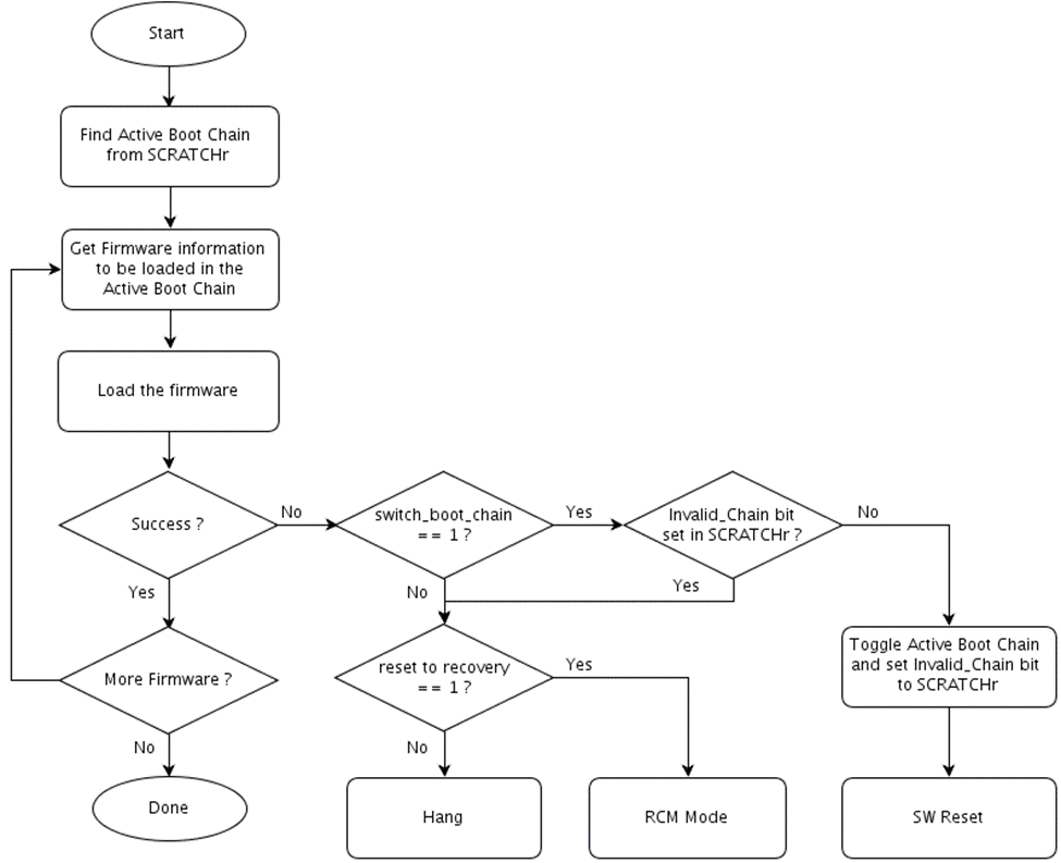
Recovery Mechanism Triggered by Loader FW
During boot when any bootloader, except BootROM, fails to load the next stage firmware, it triggers the recovery mechanism.
• Try to load next stage firmware in the Active Boot Chain.
• If it is loaded successfully, continue to boot.
• Otherwise, recovery mechanism should be triggered.
• If INVALID_CHAIN bit in the SCRTACHr register is already set to one or switch_boot_chain soft fuse value is cleared to zero, take the following recovery actions
• force the system to go to RCM mode if reset_to_recovery soft fuse value is set to one,
• force the system to hang if reset_to_recovery soft fuse value is cleared to zero.
• If INVALID_CHAIN bit is not set and switch_boot_chain soft fuse value is set to one, then set the INVALID_CHAIN bit to one and toggle the ACTIVE_BOOT_CHAIN bit in SCRATCHr register and issue reboot so that system could boot different boot chain.
The following flow chart explains this flow:
MB2 and Quickboot load Global Partition Table. This firmware component does not belong to any boot chain. Therefore, a different recovery action will be performed:
• There is a single partition to store global partition table of the system.
• This partition contains multiple signed copies of PT. If one copy is corrupted, system uses the next copy.
• Global Partition Table contains information for both boot chains of the system. As a result, the Global PT must not be erased during update. If it is erased, the system cannot be recovered without reflashing the whole images.
Partition Layout
Partition layout on flash are organized to support recovery mechanism.
• For each partition other than BR BCT and Global Partition Table, there are two partitions: Boot Chain A and Boot Chain B.
• For BR BCT, there is a single common partition. This partition will contain multiple copies of BR BCT residing at the beginning boot storage device.
• For global partition table (Global PT), there is single partition containing multiple copies of PT.