Setting Up the E3550 Platform
The NVIDIA DRIVE™ AGX hardware kit includes:
• The platform. The label on the platform may say DRIVE Main: item #1 in one box.
• All other accessories: items 2-10 in a separate box.
The hardware components are as follows:
Item Number | Label | Component and Description |
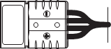
1 | DRIVE Main | NVIDIA DRIVE AGX Xavier Developer Kit |
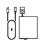
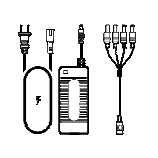
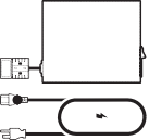
2 | System Power | Power supply, power adapter, and US power cord. |
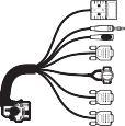
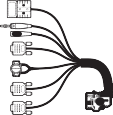
3 | Vehicle Harness | 48-pin vehicle cable harness. |
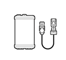
4 | RTC Module | Real-time clock module and PPS cable. |
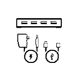
5 | ACC Power | Power adapter for accessories. |
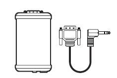
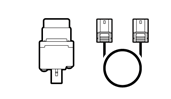
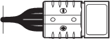
6 | Ethernet | Dual GbE dongle and HSD cable. |
7 | USB Hub | USB 3.0 hub. |
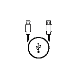
8 | USB Type A to Type A Cable | USB 2.0 Type A to Type A cable. |
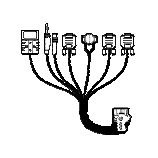
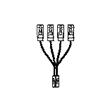
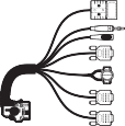
9 | Camera Breakout | Quad camera breakout cable. |
10 | Camera | Sekonix 2MP RCCB AR231 60 FOV GMSL camera and Fakra coax cable. |
• Some of the cables in the kit may not exactly match the images shown. For example, the HSD cable for the dual GbE dongle may be slightly different. • Additionally, to ensure correct connections, examine the real-time clock module and the dual GbE dongle to identify the differences in these components, as shown. |
Additional components that are required to start using the platform but are not provided include:
Component | Description |
HDMI display and cable | HDMI display monitor and associated cable to display system output. |
Keyboard | Required to interface with the system. |
Mouse | Required to navigate the system. |
The keyboard is required to use the DriveWorks samples. The mouse is useful for development purposes. A duplicate set of these items are required to operate Xavier B. |
Additional hardware that is not provided as part of the kit but is required for development purposes include:
Component | Description |
Linux host system | Required for cross-compiling, flashing, and access to the console. |
Ethernet cable | Required for internet access. |
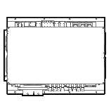
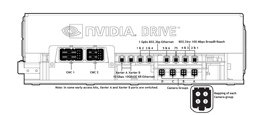
Front Panel
The front connections are as follows:
For information on mapping the camera connections, consult
Setting up the Cameras.
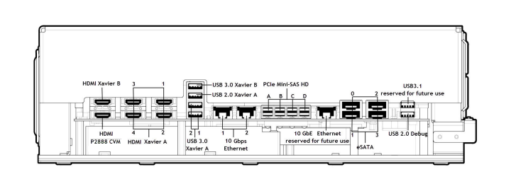
Back Panel
The back connections are as follows:
Note: | Use the USB 2.0 debug port to connect to the Linux host system to: • Flash the firmware. • Enable console access to: • Xavier A • Xavier B • P2888 CVM • Microcontroller (MCU) |
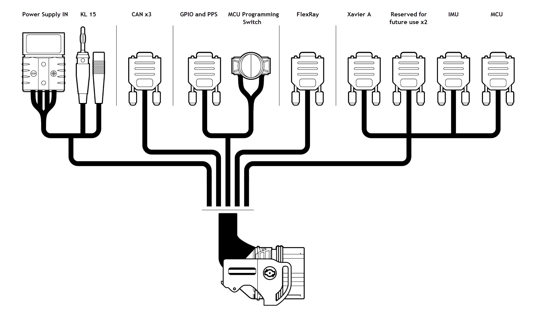
Cable Harness
The cable harness connections are as follows:
Connecting the Platform
Before making any connections, ensure the platform is not connected to the AC power supply. Failure to do so may damage the platform.
To connect the platform
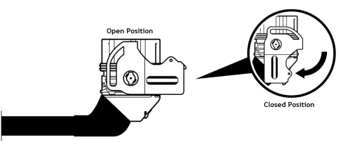
1. Verify that the latch on the vehicle harness cable is in the open position.
2. Connect the harness cable to the harness connector on the platform.
3. Lock the harness by placing the latch into the closed position.
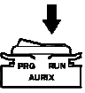
4. Ensure the MCU programming switch is set to the RUN position.
5. Connect the power supply IN connector on the vehicle cable harness to the matching power supply connection on the platform.
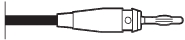
6. Connect the KL 15 ignition banana plug to the corresponding red jack located on the vehicle cable harness.
To connect a display, keyboard, and mouse to Xavier A
1. Connect an HDMI cable from the monitor to the back of the platform at Xavier A HDMI port 1.
2. Connect a USB keyboard and mouse to Xavier USB 3.0 ports 1 and 2.
Alternatively, to use one USB 3.0 port, connect the keyboard and mouse to the provided USB 3.0 hub.
Note: | The keyboard is required to interact with the DriveWorks samples. The mouse is required to develop on the platform. The platform is designed as an embedded platform, not as a development system. Consequently, a desktop is not provided at bootup. |
To connect a display, keyboard, and mouse to Xavier B
1. Connect an HDMI cable from the monitor to the back of the platform at Xavier B HDMI port.
2. Connect a USB 3.0 hub to the Xavier B USB 3.0 port.
3. Connect the keyboard and mouse to the USB 3.0 hub.
To connect to the Linux host
• Connect the USB 2.0 Type A to Type A cable from the Linux host system to the USB 2.0 debug port on the platform.
To enable internet access
1. Connect one end of the Ethernet cable to the dual GbE dongle.
2. Connect the other end of the Ethernet cable to the network Ethernet port #2.
Consult the
Back Panel image to locate the 10Gbps Ethernet port #2.
3. Connect the dongle power supply to the dual GbE dongle and plug it into an AC outlet.
Setting Up the Cameras
For detailed instructions, consult the
Camera Setup and Configuration topic.