Robot Operating System (ROS)
ROS (Robot Operating System) is open-source middleware originally developed for robotic applications but is also popular in the ADAS/AV community. It provides normally expected services, such as hardware abstraction, low-level device control, implementation of commonly-used functionality, message-passing between processes, and package management. It also provides tools and libraries for obtaining, building, writing, and running code across multiple computers. ROS is similar in some respects to other robot frameworks such as Player, YARP, Orocos, CARMEN, Orca, MOOS, and Microsoft Robotics Studio.
The ROS-based software system can be visualized as a peer-to-peer network of processes (potentially distributed across different physical systems) that are loosely coupled using the ROS communication infrastructure. ROS implements several different styles of communication, including synchronous remote procedure call (RPC) style communication over services, asynchronous streaming of data over topics, and storage of data on a parameter server. ROS is not a realtime framework, though it is possible to integrate ROS with realtime code. For example, the Willow Garage PR2 robot uses a system called pr2_etherCAT, which transports ROS messages in and out of a realtime process.
Currently, ROS only runs on Unix-based platforms. Software for ROS is primarily tested on Ubuntu and Mac OS X systems, though the ROS community has been contributing support for Fedora, Arch Linux, and other Linux platforms. ROS for Microsoft Windows is also possible, but it has not been fully explored yet.
The core ROS system, along with useful tools and libraries, are regularly released as a ROS distribution. This distribution is similar to a Linux distribution and provides a set of compatible software for others to use and build upon. As ROS is open source, many researchers are contributing to the development of libraries or packages that are compatible with the ROS distribution.
Some of the ROS distribution are Melodic, Lunar, Kinetic, Jade, Indigo, and many others. The Lunar distribution of ROS is currently the latest distribution of ROS released by the ROS community in 2017. The ROS distribution that we use is ROS Kinetic, which is primarily targeted for the Ubuntu 16.04 (Xenial) release.
Organization of ROS Framework
Organization of ROS framework can be visualized through a couple of important perspectives.
• FileSystem Perspective - ROS filesystem perspective mainly consisting of packaging forms, messaging forms, etc. that you encounter on disk.
• Packages :- Packages are the main unit for organizing software in ROS. A package may contain ROS runtime processes (nodes), a ROS-dependent library, datasets, configuration files, or anything else that is usefully organized together. Packages are the most granular thing that you can build and release in ROS.
• Metapackages :- Metapackages are specialized packages that only serve to represent a group of related other packages. Most commonly, metapackages are used as a backwards compatible place holder for converted rosbuild stacks.
• Package Manifests :- Manifests (package.xml) provide metadata about a package, including its name, version, description, license information, dependencies, and other meta information, like exported packages.
• Messages Types :- Message descriptions, stored in my_package/msg/MyMessageType.msg, define the data structures for messages sent in ROS.
• Services Types :- Service descriptions, stored in my_package/srv/MyServiceType.srv, define the request and response data structures for services in ROS.
• 2. Computation Graph Perspective - The computation graph perspective mainly consists of the peer-to-peer network of ROS processes that interact together to perform certain tasks. The basic computation graph concepts of ROS are as follows:
• Nodes :- A node is a primary computational unit in ROS. It can be thought of as a process in Linux terminology. ROS offers client libraries to program a ROS node for performing the desired tasks, namely roscpp and rospy. These client libraries facilitate programming of ROS node in either C++ or Python.
• Master :- ROS master is a base node that provides name registration and lookup to the rest of the computation graph. Without the Master, nodes would not be able to find each other, exchange messages, or invoke services.
• Messages :- Nodes communicate with each other by passing messages. A message is simply a data structure, comprising of typed fields. Standard primitive types (integer, floating point, boolean, etc.) are supported, as are arrays of primitive types. Messages can include arbitrarily nested structures and arrays (much like C structs).
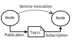
• Topics :- Messages are routed via a transport system with publish/subscribe semantics. A node sends out a message by publishing it to a given topic. The topic is a name that is used to identify the content of the message. A node that is interested in a certain kind of data will subscribe to the appropriate topic. There may be multiple concurrent publishers and subscribers for a single topic, and a single node may publish and/or subscribe to multiple topics. The idea is to decouple the production of information from its consumption. In general, publishers and subscribers are not aware of each other’s existence. Logically, you can think of a topic as a strongly typed message bus.
• Services :- The publish/subscribe model is a very flexible communication paradigm, but its many-to-many, one-way transport is not appropriate for request/reply interactions, which are often required in a distributed system. Request/reply is done via services, which are defined by a pair of message structures: one for the request and one for the reply. A providing node offers a service under a name and a client uses the service by sending the request message and awaiting the reply. ROS client libraries generally present this interaction to the programmer as if it were a remote procedure call.
• Parameter Server :- The parameter server allows data to be stored by key in a central location. It is currently part of the Master.
• Bags :- ROSBag is a ROS specific storage format. It facilitates storage of ROS message data published over a certain topic and it can be reused as required at later times.
The above figure shows two major types through which two ROS nodes can communicate. For more information on ROS and its concepts, see:
NvROS
NvROS is an NVIDIA developed middleware module that integrates the ROS framework into the DRIVE OS Linux software stack with NVIDIA DRIVE AGX as a target platform. The following are some salient features of NvROS.
• Provides a set of libraries and applications (i.e., ROS node) that utilize NVIDIA proprietary software components such as CUDA, EGLStreams, NvMedia, Driveworks, etc. to accelerate real time video/image capture and processing use cases.
• Utilizes upstream ROS packages for effective messaging and control coordination between the functional modules (i.e., ROS nodes performing a certain function).
NvROS consists of the following nodes:
1. A node performing camera capture over AR0231 sensor device and posting the captured frames into an EGLStream.
2. A node performing preview of captured data.
Note | The two nodes are independent processes and transport of captured frames takes place through EGLStream. They make use of the nvros_egl_utils library to perform EGLStream initialization. |
3. Few basic CUDA processing nodes performing simple operations such as RGB to Grey scale conversion, Sobel filter, etc.
These nodes make use of the NvROS library, which enables CUDA and EGLStream pipelining. This library enables connecting multiple CUDA-based processing elements through EGLStreams and the ROS messaging network.
4. A master controller node that launches, coordinates, and monitors the status of all the above nodes.
5. A node to encode camera or video data received over a certain EGLstream into H264 and stores it into a rosbag file.
6. A node that decodes H264 video contents moving out of a rosbag over a certain topic and posts the decoded video contents over an EGLstream for further processing.
7. A node that catches H264 video contents moving out of a rosbag over a certain topic and stores it in the form of an H264 file.
NvROS Architecture
This section describes in detail the architecture of NvROS libraries and nodes.
EGLStream Utility Library: nvros_egl_utils
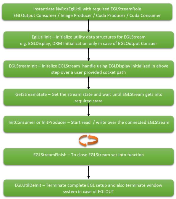
The nvros_egl_util library provides APIs that are required for the sequential setup, initialization, and close down of EGLStream. Currently, nvros_egl_utils library supports the following roles of EGLStream: EGLOutput consumer (used in camera preview, nvros_cam_preview node), CUDA producer and CUDA consumer (these two modes are used in egl_cu_io library), and image producer (used in nvros_cam_cap node).
The following figure shows the tentative sequence in which nvros_egl_utils APIs are called to set up EGLStream in one of the supported modes.
For more information on nvros_egl_utils library, see API documentation. [ Link to API document]
Camera Preview: nvros_cam_preview node
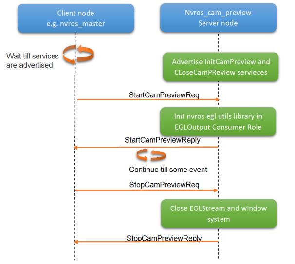
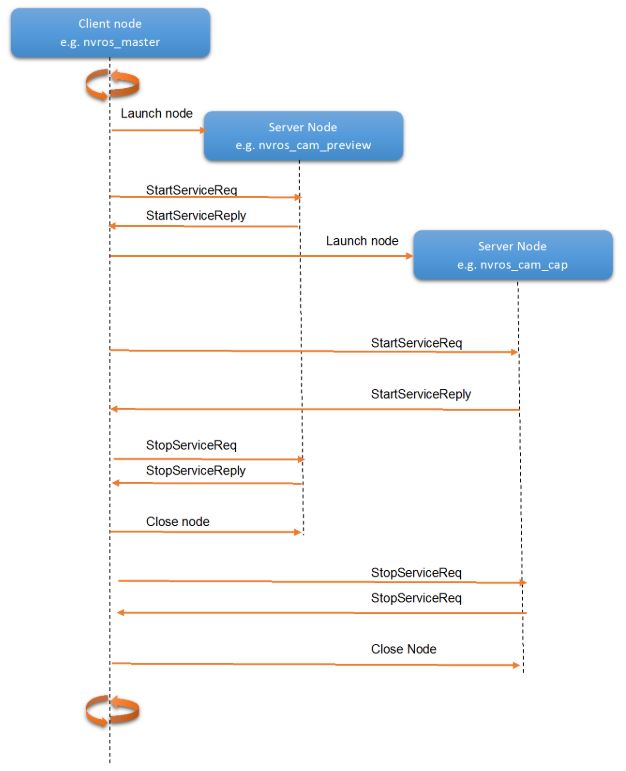
The nvros_cam_preview node displays image/video data received from a specified EGLStream. The nvros_cam_preview node is based on the request/reply interaction model of ROS known as Service defined in the ROS Organization section.[ TODO: Add link] above. The node acts as the server node, which advertises a service to which other nodes can connect for displaying contents in the EGLStream. The preview node consists of two services: one for the initialization of display and the other for the termination of display. The InitCamPreview service is used for initialization and setting up the display while the CloseCamPreview service is used for the termination of display. Currently, the preview node supports EGLStream in the image producer and video producer role at the input side and the GLlOutput role at the output side. The following sequence diagram shows the camera preview node sequence diagram.
NvROS Image Pipeline Library: nros_img_pipeline
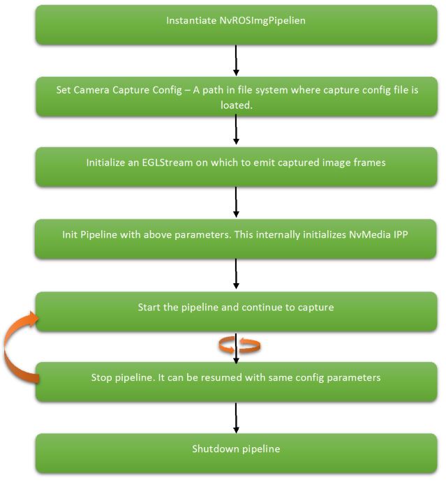
The NvROS Image Pipeline library consists of a set of APIs that facilitate setting up an image capture pipeline and putting the captured image frames onto an EGLStream. This EGLStream can be connected to a consumer for further processing or display. This library abstracts setup of the NvMedia Image Processing Pipeline (a.k.a. NvMedia IPP) within itself. This library provides simple APIs for setting camera sensor parameters, selecting the camera group for capture, setting the EGLStream socket path, initializing the pipeline, tearing down the pipeline, etc. The following figure shows the initialization sequence of the NvROS Image Pipeline.
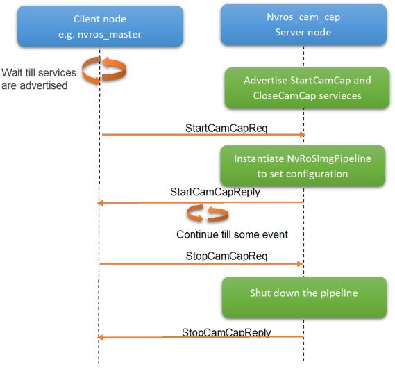
NvROS Camera Capture Node: nvros_cam_cap
Nvros_cam_cap is a node that captures image data from AR0231 cameras using the NvROS Image Pipeline library and posts it to an EGLStream for further transport. Like nvros_cam_preview node, nvros_cam_cap also depends on the request/reply interaction model of ROS. This node behaves as a server that advertises services to start/stop camera capture over a client provided configuration. The following figure shows the logical architecture of the nvros_cam_cap node.
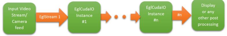
EGL Cuda IO Library: egl_cuda_io
The egl_cuda_io library contains the APIs that facilitate CUDA processing on EGLStreams. The NvRosEglCudaIO class can be treated as a pipe between two EGLStreams. The input end of this pipe, which is connected to a given EGLStream, receives the contents in the form of a CUarray, which can then be processed at the desired CUDA algorithm. The CUDA algorithm returns the processed contents again in the form of a CUarray. The output end of this pipe (i.e., NvRosEglCudaIO class) puts the processed contents into another EGLStream that then takes it up for display or another processing subsystem. Thus, the input end of the pipe acts as CUDA consumer to the EGLStream connected to the input side of the pipe, while the output end of the pipe acts as CUDA producer for the EGLStream attached to the output side. The following figure shows the logical depiction of the EGL CUDA I/O library.
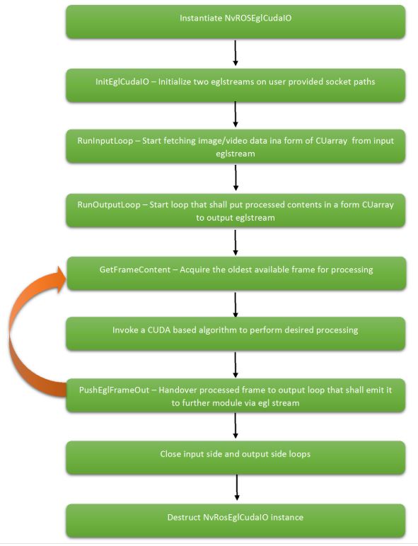
The following figure describes the initialization, processing, and teardown sequence for the egl_cuda_io library.
For more information on the egl_cuda_io library, see [TODO: Add DOxygen tag link]
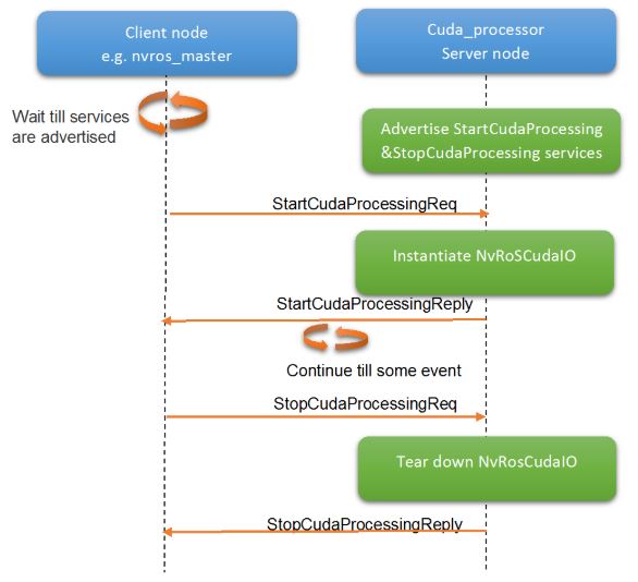
CUDA Processing Element: cuda_processing node
The cuda_processing node is a sample node that instantiates EGL CUDA I/O library to establish the pipeline. Similar to nvros_cam_preview node, it advertises services to invoke and stop certain CUDA-based algorithms on the image/video contents received over an EGLStream. This node also advertises two services. The InitCudaProcessing service initializes the EGL CUDA I/O library and accepts parameters like the socket path and CUDA algorithm identifier as arguments. Current implementation of this node includes some very basic CUDA kernels, such as RGB to Grey scale conversion, Sobel filter operator, etc. The StopCudaProcessing service invokes the termination sequence for EGL CUDE I/O library to appropriately close both EGLStream transports. The following figure depicts the logical architecture of the cuda_processing node.
Master Controller: nvros_master node
The master controller node coordinates the behavior of nodes mentioned above. It launches these nodes as children processes of itself and invokes the appropriate services provided by each node. The master node can also terminate the above launch nodes on arrival of a terminate message from the user. The following figure shows the logical architectural view of master_node.
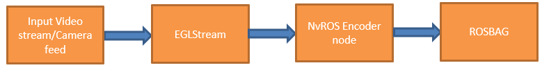
NvROS Encoder Node
The nvros_encoder node consists of H264 encoding of camera/video contents received over a certain EGLStream and stores it in a rosbag for further usage in the future. Along with encoded H264 bitstreams, ptp timestamp is also dumped in the rosbag. The encoder node acts as the consumer to the connected EGLStream while the camera/video source acts as the producer to the EGLStream.
NvROS MultiEncoder Node
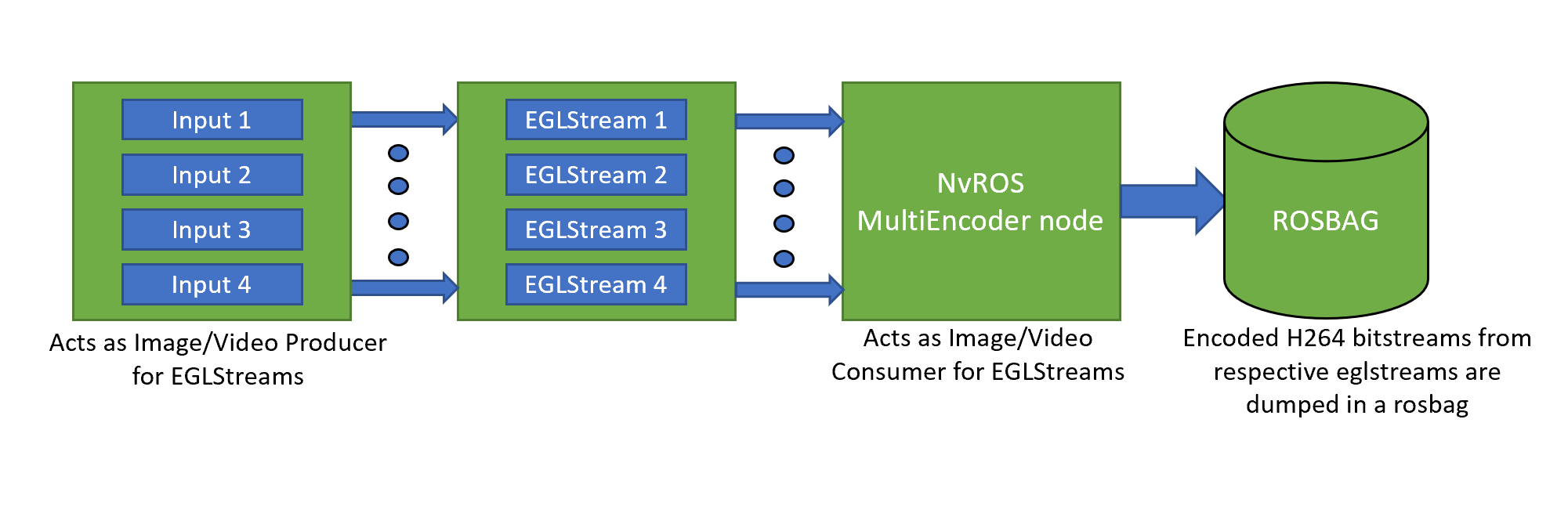
The NvROS multi-encoder node performs H.264 encoding of camera/video contents, up to four (4) EGLStreams, and stores it in a rosbag. Along with encoded H.264 bitstreams, the PTP timestamp is also recorded. The following figure shows the logical architectural view of multi-encoder node.
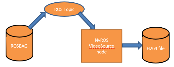
NvROS Video Source Node
The video source node accesses a given rosbag populated with H.264 encoded video contents via ROS topic and writes a H.264 stream into a video file. The restored video is decoded by a compatible video decoding application.
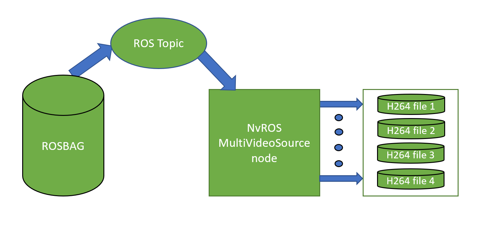
NvROS Multi Video Source Node
The NvROS multi-videosource node accesses a given rosbag populated with H.264 encoded video contents from different camera/video file sources via ROS topic and writes respective H.264 encoded streams into appropriate video files. The restored video files are decoded by a compatible video decoding application. The number of video files created by multi-videosource node depends on the number of producer sources whose encoded data is dump in the given rosbag accessed by multi-videosource node. The multi-videosource node supports the creation of a maximum of four (4) video files from a given rosbag. The following figure shows the logical architecture view of multi-videosource node.
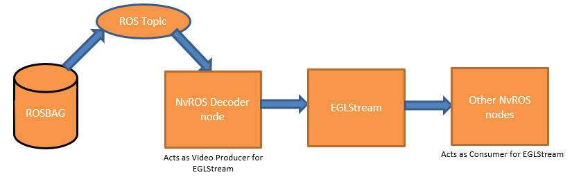
NvROS Video Decoder Node
The nvros_decoder node receives H.264 encoded video streams over a ROS topic. The node decodes the received bitstream from topic and then posts it to certain EGLStreams, which can then be available to other NvROS nodes for further processing. The decoder node acts as the producer to the connected EGLStream while the other NvROS nodes acts as the consumer to the EGLStream. The egl_socket path for decoder is hard-coded in node. The egl_socket path used for consumer node is /tmp/nvros_egl_socket_decoder.
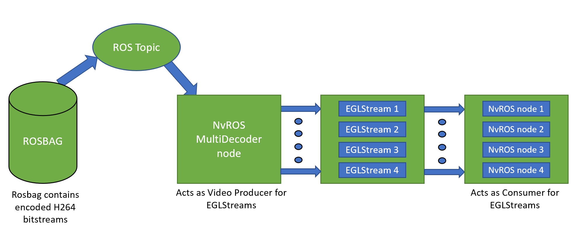
NvROS Multi Video Decoder Node
The NvROS multi-decoder node receives H.264 encoded video streams from different camera/video file sources over an ROS topic. The multi-decoder node decodes the received bitstreams and then posts them to the appropriate number of EGLStreams, which can then be available to other NvROS nodes for further processing. The multi-decoder node acts as a producer connected to multiple EGLStreams while the other NvROS nodes connected to those EGLStreams act as the consumer. The multi-decoder node supports a maximum of four (4) EGLStream connections for decoding. The following figure shows the logical architectural view of multi-decoder node.
NvROS Sensors
The nvros_sensors package IMU, GPS, CAN, Radar, and Lidar sensor nodes.
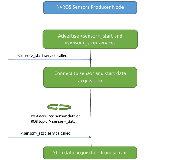
The producer node leverages DriveWorks SDK to capture sensor data and post to the respective ROS topic. Producer node advertises the services ‘<sensor>_start’ and ‘<sensor>_stop’ to control the data acquisition from the sensors.
Consumer node subscribes to the ROS topic, interprets and logs the relevant values of the message received to the console. It also packages visualization nodes for Radar and Lidar sensors.
• GPS
GPS producer works with any serial port (UART) based GPS sensor or with the Xsens GPS device connected over USB. It requires the GPS sensor connected over serial port to deliver messages in NMEA format, while XSens sensor can run in proprietary mode.
• IMU
The IMU node works with any serial port (UART) based IMU sensor or with the Xsens IMU device connected over USB. It requires the IMU sensor connected over serial port to deliver messages in NMEA format, while the Xsens device can run in proprietary mode.
• CAN
The CAN node is a simple CAN bus listener. All messages received over the CAN bus are printed on the console. A valid SocketCAN or AurixCAN device must be present in the system.
An interpreter is built based either on the definition in a DBC file or a set of user-provided callbacks and input CAN messages are then decoded by the interpreter.
Information about car steering and speed is transmitted in CAN messages, and the node decodes and publishes all received CAN messages.
• Radar
The Radar node connects to a Radar and sends the generated point cloud over shared memory. The Radar must be up and running, and connected to the network.
• Lidar
The Lidar node connects to a Lidar and sends the generated point cloud over shared memory. The Lidar must be up and running, and connected to the network.
NvROS Rectifier Node
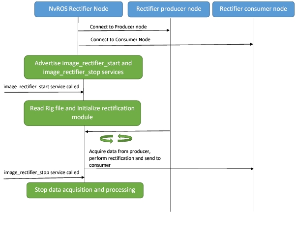
The nvros_rectifier module removes fisheye distortion from the video captured on a camera with a fisheye lens.
The node reads frames from eglstream and takes the calibration from a rig file. It then performs rectification and send out the rectified frame on eglstream.
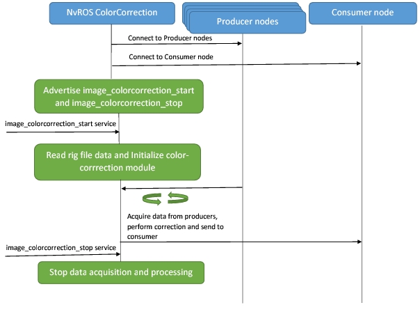
NvROS ColorCorrection Node
Note | This node must be configured to use only the iGPU, via use of the CUDA_VISIBLE_DEVICES environment variable. |
The nvros_colorcorrection module performs color correction by reprojecting all cameras into a common plane, where the common plane is the ground plane. It equalizes the hue of the ground texture to the selected master camera.
It accepts RGBA Pitch linear CUDA images from 4 eglstreams, performs color correction and send out RGBA block CUDA linear images on 4 eglstreams.
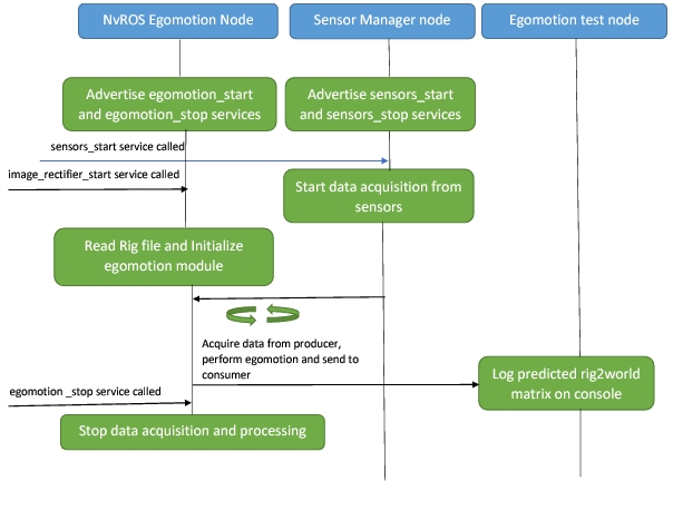
NvROS Egomotion Node
The nvros_egomotion package uses steering angle and velocity CAN measurements (from nvros_sensors package) to compute vehicle position and orientation within the world coordinate system by leveraging dwEgomotion module.
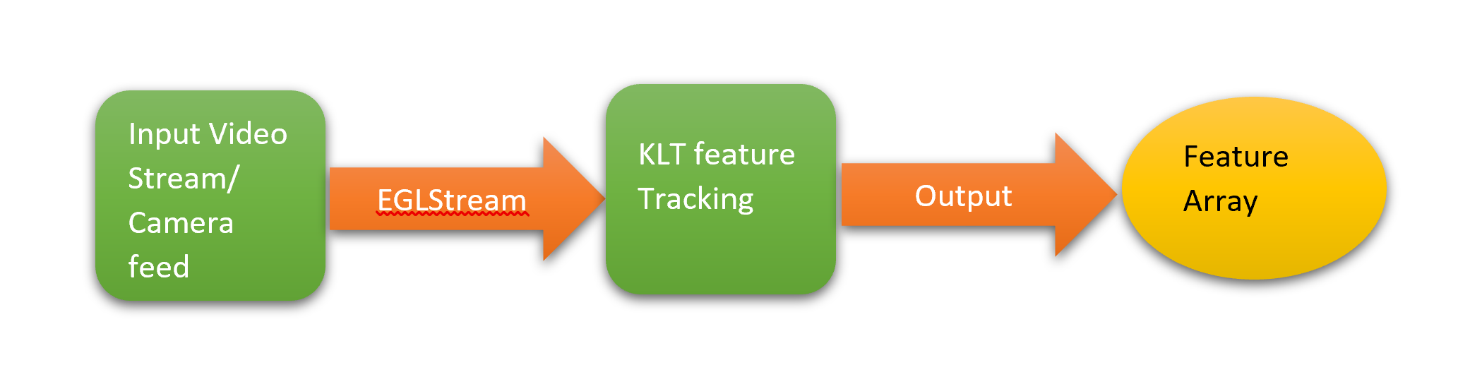
NvROS Feature Tracking Library
The nvros_dw_utils package (written as a class) implements feature tracking for a given image. It exposes several APIs to enable the above functionality, as follows:
• API for Frame capture - Initializes eglstream, starts frame capture, and captures the image.
• API to start feature tracking on the captured frame and extracts the feature data.
The feature tracking implementation is a part of the DriveWorks library, which is referenced here through external APIs.
Here’s a high level overview of how the library works:
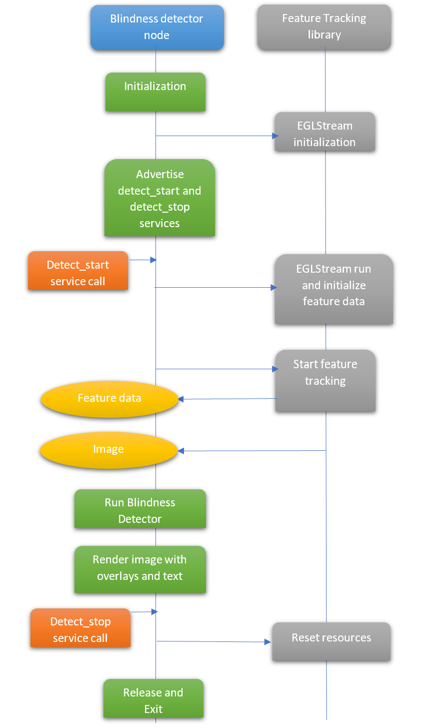
NvROS Camera Blindness Detector Node
The nvros_camera_blindness package detects camera blindness proportion for a given frame. It utilizes the feature tracking library to get the frame and detect/track features. The data is then processed by blindness detector APIs present in DriveWorks. An image with relevant overlays with text is displayed.
Here’s a high-level overview of the call flow:
NvROS TensorRT Integration
NVIDIA TensorRT is a platform for high-performance deep learning inference. It includes an inference optimizer and a runtime that delivers low latency and high throughput for deep learning inference.
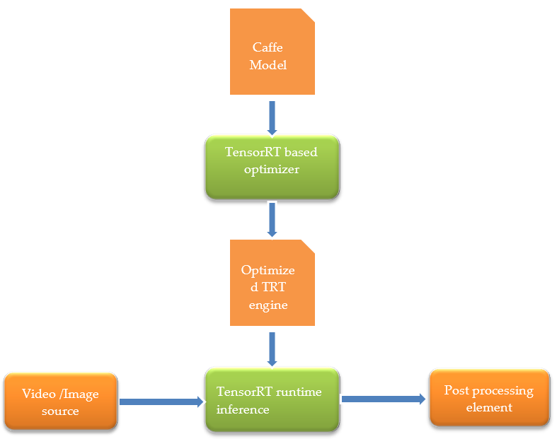
TensorRT is developed on top of CUDA. Therefore, to integrate TensorRT with NvROS, the egl_cuda_io library is used. This library sets up connections for input and output EGLStreams so that the inference can be performed on incoming data streams and can be passed to another EGLStream for further processing. Inference over a certain DNN model using TensorRT involves the following two major steps:
1. Generate TensorRT optimized engine file.
2. Actual inference using the optimized engine file.
The following figure depicts how NvROS integrates TensorRT with the above two steps:
For detailed information about TensorRT, see:
and API documentation located at:
TensorRT APIs are available in C++ and Python. NvROS exercises C++ APIs in its integration.
NvROS VPI Integration
Programmable Vision Interface (PVA) is a hardware module in NVIDIA Xavier SoC that accelerates certain Computer Vision (CV) algorithms. Functionality of this hardware module is programmed through the NvMedia Vision Programming Interface (VPI). For more information on NvMedia VPI, see NvMedia Vision Programming.
The 2D convolution algorithm is supported in NvROS-VPI integration.
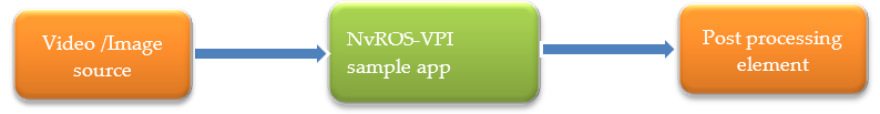
The following figure depicts NvROS-VPI integration architecture. It is logically similar to modules like NvROS-TensorRT integration or NvROS EGL CUDA Interop. The only difference is that the data being passed in the processing pipeline is an image buffer instead of a CUDA buffer.
NvROS-VPI integration implementation supports image or video data of surface type YUV420 Semi-Planar.
Executing NvROS Applications
This section describes the execution of NvROS applications on the target filesystem.
Ensure that NvROS is installed at the target filesystem location at /home/nvidia/nvros. Install the prerequisite packages for ROS by executing the following commands:
$ sudo apt-add-repository universe
$ sudo apt-get update
$ sudo apt-get install libboost-all-dev libtinyxml-dev liblz4-dev libbz2-dev libapr1 libaprutil1 libconsole-bridge-dev python-defusedxml python-rospkg python-catkin-pkg python-netifaces
Initialize the ROS environment by executing the following commands:
$ cd $HOME/nvros/install_isolated
$ source setup.bash
$ roscore &
$HOME/ros/install_isolated is referred to as NVROS_TOP. To execute some NvROS applications, a set of nvm_eglstream apps is needed. They are located at $HOME/ros/nvm_eglstream_samples. For convenience, add this to $PATH.
export PATH=$PATH:$HOME/nvros/nvm_eglstream_samples
Close the gdm3 service of Ubuntu, as NvROS apps use EGLDevice to display.
sudo service gdm3 stop
sudo pkill X
Test Applications
Test_img_pipeline:- This test application validates the nvros_img_pipeline library. It performs camera capture in two ways:
• Tegra X1 capture is performed via two cameras in group 0:
$ test_nvros_egl_image_consumer -d 0 -s /tmp/nvros_cam_0_0
$ test_nvros_egl_image_consumer -d 1 -s /tmp/nvros_cam_0_1
$ test_img_pipeline -t x1
The captured stream is displayed on two displays.
• Tegra X2 capture is performed via a single camera in group 0:
$ test_nvros_egl_image_consumer -d 0 -s /tmp/nvros_cam_0_0
$ test_img_pipeline -t x2
Test_img_pipeline:- This test application validates the nvros_img_pipeline library. It performs camera capture through camera devices connected to group 0 of the NVIDIA DRIVE AGX target platform and creates an EGLStream instance over /tmp/nvmedia_egl_socket and waits for a consumer to connect to it.
The test_img_pipeline application has a timeout of 20 sec. The application exits after 20 seconds.
$ nvm_eglstream -standalone 2 -producer 1 -consumer 0 -d 0
$ test_img_pipeline
Test_eglconsumer:- This test application validates nvros_egl_util library. It creates an EGLStream instance over socket /tmp/nvmedia_egl_socket in an EGLOutput consumer role and waits for a cross process producer to connect.
1. To run test_eglconsumer with video producer using an H264 file:
$ test_nvros_egl_utils_consumer
$ nvm_eglstream -standalone 1 -producer 0 -consumer 4 -f [Input h264 file]
2. To run test_eglconsumer with image producer using a YUV file:
$ test_nvros_egl_utils_consumer
$ nvm_eglstream -standalone 1 -producer 1 -consumer 4 -f [Input yuv file] -fr [dimesnsions]
Note | The nvm_eglstream sample app is also available at /home/nvidia/drive-t186ref-linux/samples/nvmedia/eglstream/egldevice. |
Test_egl_cuda_io:- This test application validates egl_cuda_io library. It creates two EGLStream instances: one in the CUDA producer role and the other in the CUDA consumer role, and waits for two other cross process producers and consumers to connect.
• To run test_egl_cuda_io_single_stream - This app connects to a video producer, performs Sobel filter operation, and displays it via another cross-process video consumer instance.
$ nvm_eglstream_out -d 0 -standalone 2 -producer 3 -consumer 0
$ test_egl_cuda_io_single_stream
$ nvm_eglstream -standalone 1 -producer 0 -consumer 3 -f [Input h264 file] -fifo
• To run test_egl_cuda_io_multistream - This test app connects to four instances of video producer, scales each of them to half, and displays all four via another cross-process video consumer instance. For accurate results, ensure that all four videos have the same frame dimensions.
$ nvm_eglstream_out -d 0 -standalone 2 -producer 3 -consumer 0
$ test_egl_cuda_io_multistream
$ nvm_eglstream -standalone 1 -producer 0 -consumer 3 -f [Input h264 file 1] -fifo
$ nvm_eglstream_in_2 -standalone 1 -producer 0 -consumer 3 -f [Input h264 file 2] -fifo
$ nvm_eglstream_in_3 -standalone 1 -producer 0 -consumer 3 -f [Input h264 file 3] -fifo
$ nvm_eglstream _in_4 -standalone 1 -producer 0 -consumer 3 -f [Input h264 file 4] -fifo
Test_cuda_kernel:- This test application validates APIs exposed by nvros_cuda_kernels library to:
• Convert CUDA images from Pitch Linear memory type to Block Linear and vice-versa.
• Convert CUDA images in Pitch Linear memory type from RGBA color format to YUV420 Planar and vice-versa.
It creates two EGLStream instances: one in the CUDA producer role and the other in the CUDA consumer role, and waits for two other cross process producers and consumers to connect.
• To run test_cuda_kernel_pitch_to_block - This test node accepts RGBA CUDA images from EGLStream producer in Pitch Linear memory type, converts them to Block Linear memory type, and posts them on EGLStream to another cross-process video consumer instance (for display).
$ nvm_eglstream_out -standalone 2 -producer 3 -consumer 1 -d 0 -ot rgba -fifo
$ test_cuda_kernel_pitch_to_block
$ nvm_eglstream -standalone 1 -producer 0 -consumer 3 -f [Input h264 file] -pl -l 5 -ot rgba -fifo
• To run test_cuda_kernel_block_to_pitch- This test node accepts RGBA CUDA images from EGLStream producer in Block Linear memory type, converts them to Pitch Linear memory type, and posts them on EGLStream to another cross-process video consumer instance (for display).
$ nvm_eglstream_out -standalone 2 -producer 3 -consumer 1 -d 0 -ot rgba -pl -fifo
$ test_cuda_kernel_block_to_pitch
$ nvm_eglstream -standalone 1 -producer 0 -consumer 3 -f [Input h264 file] -l 5 -ot rgba -fifo
• To run test_cuda_kernel_rgba_yuv420- This test node accepts RGBA CUDA images from EGLStream producer in Pitch Linear memory type, converts them to YUV420 Planar color format, converts the YUV420 Planar images back to RGBA color format with Pitch Linear memory type, and posts them on EGLStream to another cross-process video consumer instance (for display).
$ nvm_eglstream_out -standalone 2 -producer 3 -consumer 1 -d 0 -ot rgba -pl -fifo
$ test_cuda_kernel_rgba_yuv420
$ nvm_eglstream -standalone 1 -producer 0 -consumer 3 -f [Input h264 file] -pl -l 5 -ot rgba -fifo
Master Controller Node: - As described in the
NvROS-Architecture section, the master controller node coordinates the behavior of various nodes. According to the config file that is passed as an argument, it invokes the appropriate services provided by each node.
Camera Capture + Cuda Processor + Preview: - In this combination, master nodes launch following three nodes:
1. nvros_cam_cap to perform camera capture
2. cuda_processor to perform CUDA based image processing
3. nvm_eglstream_out to view the processed image on the display
$ nvros_master -c $NVROS_TOP/etc/nvros_master/nvros-camera-cuda.nvroscfg
Camera Capture + Preview: - In this combination, the master node launches the following two nodes:
1. nvros_cam_cap to perform camera capture
2. nvros_cam_preview to view the captured contents on display
$ nvros_master -c $NVROS_TOP/etc/nvros_master/nvros-camera-preview.nvroscfg
Note | To execute these two node combinations, ensure that camera configuration files, ddpx-a.conf and ddpx-b.conf, are available at /home/nvidia. |
Process Video + Preview: - In this combination, CUDA based image processing is performed on a video. The master node launches the following three nodes:
1. nvm_eglstream in video producer mode
2. cuda_processor to perform CUDA based processing
3. nvm_eglstream_out to view the processed contents.
$ nvros_master -c $NVROS_TOP/etc/nvros_master/nvros-camera-cuda.nvroscfg
Note | Ensure that the path of the video file specified in nvros-cuda.nvrosconfig is valid. If it is not, manually edit the file path. |
Note | During execution of CUDA based NvROS nodes, some EGL and CUDA related errors e.g., Error callback from EglCudaIO Lib, Err : 1 , No frames available in the Queue , Error in presenting egl frame to eglStream are likely to be observed. These are not the functional errors but represent a condition that the video file under test has finished playing. |
A note about integrating existing or custom ROS nodes into an NvROS environment:
NvROS fundamentally consists of two parts:
1. ROS bare bone framework (a.k.a. ROS comms)
2. Libraries, test applications, and ROS nodes developed by NVIDIA that function over a custom message.
To include an existing ROS node into NvROS, a safe, recommended way is to cross compile ROS node in a catkin environment that is set up as described in the
Cross Compiling ROS section in this document. You may need to include additional ROS packages into the bare bone ROS as required. The compiled binaries are copied onto NVIDIA DRIVE AGX using standard utilities, such as
scp or a USB mass storage device, etc. It is also possible to directly install ROS on NVIDIA DRIVE AGX using the Ubuntu package manager, but it may cause duplication of the ROS framework on the same system and may result in undefined behavior if the two workspaces are not maintained diligently.
NvROS Video Codec Nodes
NvROS Encoder Node
NvROS encoder node uses ptp timestamps. In order to get valid timestamps for the encoded video/camera frames, perform time synchronization between AURIX and the SoC. For more information, see
Time Synchronization between AURIX and the SoC Using gPTP.1. Get ownership of device node /dev/ptp0:
$ sudo chown nvidia /dev/ptp0
2. Launch the encoder node:
$ nvros_encoder -s /tmp/nvmedia_egl_socket
3. Start the video producer using NvMedia EGLStream sample:
$ nvm_eglstream -standalone 1 -producer 0 -consumer 1 -f <h264 video file>
An nvros_video.bag rosbag file is dumped in the current working directory.
NvROS Video Source Node
1. Start NvROS video source node:
$ nvros_videosource
2. Play the rosbag:
$ rosbag play -d 5 nvros_video.bag
An nvros_video.h264 H264 video file is dumped in the current working directory. Play it with the NvMedia video playback sample application.
$ nvmvid_play -c 4 -d 0 -f nvros_video.h264
NvROS Video Decoder Node
1. Run a test application for display:
$ test_nvros_egl_image_consumer -d 0 -s /tmp/nvros_egl_socket_decoder
2. Run NvROS decoder:
$nvros_decoder
3. Play the rosbag:
$ rosbag play -d 5 nvros_video.bag
Decoded video contents are displayed on Display 0.
NvROS MultiEncoder Node
NvROS multi encoder node uses PTP timestamps. In order to get valid timestamps for the encoded video/camera frames, perform time synchronization between AURIX and the SoC.
1. Get ownership of device node /dev/ptp0
$ sudo chown nvidia /dev/ptp0
2. Launch multi encoder node
$ multi_videnc -n [num of eglstreams] -s [corresponding eglstreams socket paths]
3. Start the corresponding video producer using the NvMedia EGLStream sample.
$ nvm_eglstream -standalone 1 -producer 0 -consumer 1 -f <h264 video file>
$ nvm_eglstream_in_2 -standalone 1 -producer 0 -consumer 0 -f <h264 video file>
$ nvm_eglstream_in_3 -standalone 1 -producer 0 -consumer 0 -f <h264 video file>
$ nvm_eglstream_in_4 -standalone 1 -producer 0 -consumer 0 -f <h264 video file>
A rosbag file named nvros_video.bag containing encoded data of the given number of EGLStreams connected to multi-encoder node is dumped in the current working directory. The order of encoded data present in the rosbag depends on the order in which EGLStreams are connected to the multi-encoder node and on the start and end time of the video/camera producer source connected to that respective EGLStream.
Examples of the execution of multi-encoder nodes with the appropriate number of sample EGLStreams apps:
1. Multi-Encoder node + Single EGLStream app:
$ multi_videnc -n 1 -a /tmp/nvmedia_egl_socket
$ nvm_eglstream -standalone 1 -producer 0 -consumer 1 -f <h264 video file>
2. Multi-Encoder node + Two EGLStream apps:
$ multi_videnc -n 2 -a /tmp/nvmedia_egl_socket -b /tmp/nvmedia_egl_socket_in_2
$ nvm_eglstream -standalone 1 -producer 0 -consumer 0 -f <h264 video file>
$ nvm_eglstream_in_2 -standalone 1 -producer 0 -consumer 0 -f <h264 video file>
3. Multi-Encoder node + Three EGLStream apps:
$ multi_videnc -n 2 -a /tmp/nvmedia_egl_socket -b /tmp/nvmedia_egl_socket_in_2 -c /tmp/nvmedia_egl_socket_in_3
$ nvm_eglstream -standalone 1 -producer 0 -consumer 0 -f <h264 video file>
$ nvm_eglstream_in_2 -standalone 1 -producer 0 -consumer 0 -f <h264 video file>
$ nvm_eglstream_in_3 -standalone 1 -producer 0 -consumer 0 -f <h264 video file>
4. Multi-Encoder node + Four EGLStream apps:
$ multi_videnc -n 4 -a /tmp/nvmedia_egl_socket -b /tmp/nvmedia_egl_socket_in_2 -c /tmp/nvmedia_egl_socket_in_3 -d /tmp/nvmedia_egl_socket_in_4
$ nvm_eglstream -standalone 1 -producer 0 -consumer 0 -f <h264 video file>
$ nvm_eglstream_in_2 -standalone 1 -producer 0 -consumer 0 -f <h264 video file>
$ nvm_eglstream_in_3 -standalone 1 -producer 0 -consumer 0 -f <h264 video file>
$ nvm_eglstream_in_4 -standalone 1 -producer 0 -consumer 0 -f <h264 video file>
NvROS MultiVideoSource Node
1. Start NvROS multi-videosource node:
$ multi_vidrsc -n [num of streams]
2. Play the rosbag:
$ rosbag play -d 5 nvros_video.bag
The number of streams entered while executing multi-videosource node depends on the number of sources whose H.264 encoded data is present in the given rosbag. The H.264 video files are dumped in the current working directory, depending on the number of streams entered while executing multi-videosource node. A maximum of four (4) H.264 video files can be created by multi-videosource node. The name of dumped H.264 video files are nvros_video_0.h264, nvros_video_1.h264, nvros_video_2.h264, and nvros_video_3.h264.
Use the NvMedia video playback sample application to play the H.264 video files.
$ nvmvid_play -c 4 -d 0 -f nvros_video_0.h264
$ nvmvid_play -c 4 -d 0 -f nvros_video_1.h264
$ nvmvid_play -c 4 -d 0 -f nvros_video_2.h264
$ nvmvid_play -c 4 -d 0 -f nvros_video_3.h264
NvROSMultiDecoder Node
1. Run test applications for display:
$ test_nvros_egl_image_consumer -d 0 -s [eglstream socket path]
$ test_nvros_egl_image_consumer -d 1 -s [eglstream socket path]
$ test_nvros_egl_image_consumer -d 2 -s [eglstream socket path]
$ test_nvros_egl_image_consumer -d 3 -s [eglstream socket path]
2. Run NvROS multi-decoder:
$ multi_viddec -n [num of eglstreams] -s [corresponding eglstreams socket paths]
3. Play the rosbag:
$ rosbag play -d 5 nvros_video.bag
The number of streams entered while executing multi-decoder node depends on the number of sources whose H.264 encoded data is dumped in the given rosbag. Decoded video contents from the rosbag aredisplayed on Display 0, Display 1, Display 2, and Display 3, respectively. The display timing of the data on each display is not necessarily the same as it depends on the order in which H.264 encoded video/camera data is present in the given rosbag. There is a chance that some display applications may start early/late or exit early/late in comparison to other display applications.
Examples for execution of multi-decoder nodes with the appropriate number of test application for displays:
1. Single test display app + Multi-Decoder node:
$ test_nvros_egl_image_consumer -d 0 -s /tmp/nvmedia_egl_socket
$ multi_viddec -n 1 -a /tmp/nvmedia_egl_socket
$ rosbag play -d 5 nvros_video.bag
2. Two test display apps + Multi-Decoder node:
$ ./nvm_eglstream -standalone 2 -producer 0 -consumer 0 -d 0
$ ./nvm_eglstream_in_2 -standalone 2 -producer 0 -consumer 0 -d 1
$ multi_viddec -n 2 -a /tmp/nvmedia_egl_socket -b /tmp/nvmedia_egl_socket_in_2
$ rosbag play -d 5 nvros_video.bag
3. Three test display apps + Multi-Decoder node:
$ ./nvm_eglstream -standalone 2 -producer 0 -consumer 0 -d 0
$ ./nvm_eglstream_in_2 -standalone 2 -producer 0 -consumer 0 -d 1
$ ./nvm_eglstream_in_3 -standalone 2 -producer 0 -consumer 0 -d 2
$ multi_viddec -n 3 -a /tmp/nvmedia_egl_socket -b /tmp/nvmedia_egl_socket_in_2
-c /tmp/nvmedia_egl_socket_in_3
$ rosbag play -d 5 nvros_video.bag
4. Four test display apps + Multi-Decoder node:
$ ./nvm_eglstream -standalone 2 -producer 0 -consumer 0 -d 0
$ ./nvm_eglstream_in_2 -standalone 2 -producer 0 -consumer 0 -d 1
$ ./nvm_eglstream_in_3 -standalone 2 -producer 0 -consumer 0 -d 2
$ ./nvm_eglstream_in_4 -standalone 2 -producer 0 -consumer 0 -d 3
$ multi_viddec -n 4 -a /tmp/nvmedia_egl_socket -b /tmp/nvmedia_egl_socket_in_2
-c /tmp/nvmedia_egl_socket_in_3 -d /tmp/nvmedia_egl_socket_in_4
$ rosbag play -d 5 nvros_video.bag
NvROS Sensors Nodes
1. Run NvROS producer node:
$nvros_sensor_producer
2. Run NvROS consumer node:
$nvros_sensor_consumer
3. Call rosservice to start sensor data acquisition
GPS: $rosservice call gps_start gps.virtual file=<filename-with-path>
IMU: $rosservice call imu_start imu.virtual file=<filename-with-path>
CAN: $rosservice call can_start can.virtual file=<filename-with-path> true can.dbc Steering_Report.SPEED Steering_Report.ANGLE
Radar: $rosservice call radar_start radar.virtual file=<filename-with-path>
Lidar: $rosservice call lidar_start lidar.virtual file=<filename-with-path>
4. Run Radar/Lidar visualization node:
$nvros_radar_visualization
The Radar visualization node opens a window to display a 3D point cloud. In addition to the points, the output contains directed unit velocity vectors. The direction vectors are rendered in a few different colors, based on the speed ranges.
Worldspace axes: Red-OX, Blue-OY, Green-OZ.
The following interactions with the radar visualization are available at runtime:
• Mouse left button: rotate the point cloud
• Mouse wheel: zoom in or out
$nvros_lidar_visualization
The Lidar visualization node opens a window to display a 3D point cloud.
The following interactions with the lidar visualization are available at runtime:
• Mouse left button: rotate the point cloud
• Mouse wheel: zoom in or out
5. Call rosservice to stop sensor data acquisition:
GPS: $rosservice call gps_stop
IMU: $rosservice call imu_stop
CAN: $rosservice call can_stop
Radar: $rosservice call radar_stop
Lidar: $rosservice call lidar_stop
Sensor | Services Advertised | Input Parameters (type-name) | Comments | Return Value (type-name) | Comments | Message Topic |
GPS | gps_start | string driver | GPS sensor protocol | bool success | 'true' if successful, 'false' otherwise | /gps_data |
string params | Auxiliary params. comma separated 'key=value' parameters for the sensor. |
gps_stop | | | bool success | 'true' if successful, 'false' otherwise |
IMU | imu_start | string driver | IMU sensor protocol | bool success | 'true' if successful, 'false' otherwise | /imu_data |
string params | Auxiliary params. comma separated 'key=value' parameters for the sensor. |
imu_stop | | | bool success | 'true' if successful, 'false' otherwise |
CAN | can_start | string driver | CAN sensor protocol | bool success | 'true' if successful, 'false' otherwise | /can_data |
string params | Auxiliary params. comma separated 'key=value' parameters for the sensor. |
bool dbc | Specifies whether to use DBC file or callbacks for interpreter |
string dbcFile | Location of DBC file. |
string canSpeedName | CAN bus symbol for speed data |
string canSteeringAngleName | CAN bus symbol for steering angle data |
can_stop | | | bool success | 'true' if successful, 'false' otherwise |
Radar | radar_start | string driver | Radar sensor protocol | bool success | 'true' if successful, 'false' otherwise | /radar_data |
string params | Auxiliary params. comma separated 'key=value' parameters for the sensor. |
radar_stop | | | bool success | 'true' if successful, 'false' otherwise |
Lidar | lidar_start | string driver | Radar sensor protocol | bool success | 'true' if successful, 'false' otherwise | /lidar_data |
string params | Auxiliary params. comma separated 'key=value' parameters for the sensor. |
lidar_stop | | | bool success | 'true' if successful, 'false' otherwise |
NvROS Rectifier Node
1. Start Producer node:
$ rectifier_producer -standalone 1 -producer 0 -consumer 1 -f <video-file> -ot yuv420
2. Start Consumer node:
$rectifier_consumer -standalone 2 -producer 0 -consumer 0 -d 0 -ot yuv420
3. Start Rectifier node:
$nvros_rectifier
4. Call rosservice to start processing:
$rosservice call image_rectifier_start rig.json pinhole SVIEW_FR 120 90
Services Advertised | Input Parameters (type-name) | Comments | Return Value (type-name) | Comments |
image_rectifier_start | string rigFile | Points to the rig file that contains calibration information | bool success | 'true' if successful 'false' otherwise |
string outCamera | 'pinhole' or 'ocam' |
string cameraName | Is the camera name in the rig configuration file |
float32 fovX | Defines the field of view of the camera along the X axis |
float32 fovY | Defines the field of view of the camera along the Y axis |
image_rectifier_stop | | | bool success | 'true' if successful 'false' otherwise |
image_rectifier_update_translation | char axis | 'x', 'y' or 'z'. Camera translation axis. | bool success | 'true' if successful 'false' otherwise |
float32 value | Value of trandlation along slected axis. Range: [-1.0, 1.0] |
NvROS ColorCorrection Node
1. Select iGPU to run the node. This must be done on all terminals running colorcorrection related nodes.
$ export CUDA_VISIBLE_DEVICES=1
2. Start the consumer node:
$ test_nvros_egl_image_consumer -d 0 -s /tmp/nvmedia_egl_socket_out
3. Start multistream CUDA consumer (to arrange outputs of four (4) cameras on screen):
$ test_egl_cuda_io_multistream
4. Start producer nodes:
$producer0 -standalone 1 -producer 0 -consumer 3 -f <filename> -pl -ot rgba -fifo
$producer1 -standalone 1 -producer 0 -consumer 3 -f <filename> -pl -ot rgba -fifo
$producer2 -standalone 1 -producer 0 -consumer 3 -f <filename> -pl -ot rgba -fifo
$producer3 -standalone 1 -producer 0 -consumer 3 -f <filename> -pl -ot rgba -fifo
5. Start color correction node:
$nvros_colorcorrection
6. Call rosservice to start processing:
$ rosservice call image_colorcorrection_start rig.json 0 0.8
Services Advertised | Input Parameters (type-name) | Comments | Return Value (type-name) | Comments |
image_colorcorrection_start | string rigFile | Points to the rig file that contains calibration information | bool success | 'true' if successful 'false' otherwise |
uint32 reference | Specifies the reference camera. Range [0,3] |
float32 factor | Specifies the color correction factor. 0 means no correction (original video) and 1 means fully using the master camera's color |
image_colorcorrection_stop | | | bool success | 'true' if successful 'false' otherwise |
image_colorcorrection_update_reference | float32 factor | Specifies the color correction factor. 0 means no correction (original video) and 1 means fully using the master camera's color | bool success | 'true' if successful 'false' otherwise |
uint32 reference | Specifies the reference camera. Range [0,3] |
NvROS Egomotion Node
1. Start egomotion node:
$nvros_egomotion
2. Start sensor manager node:
$nvros_sensor_manager
3. Start egomotion consumer node
$test_egomotion
4. Call rosservice to start data acquisition and processing:
$rosservice call egomotion_start rig-nominal-intrinsics.json 1.0 14.8
$rosservice call sensors_start rig-nominal-intrinsics.json can.dbc Steering_Report.SPEED Steering_Report.ANGLE
Services Advertised | Input Parameters (type-name) | Comments | Return Value (type-name) | Comments |
egomotion_start | string rigFile | Points to the rig file that contains calibration information | bool success | 'true' if successful 'false' otherwise |
float32 velocityFactor | CAN speed factor. kph -> m/s |
float32 steeringFactor | CAN steering wheel angle factor |
egomotion_stop | | | bool success | 'true' if successful 'false' otherwise |
egomotion_estimate | uint64 timestamp_up | Timestamp at which the prediction needs to be obtained | bool success | 'true' if successful 'false' otherwise |
float32[16] rig2world | Predicted rig2world matrix, if estimation is successfull |
NvROS Camera Blindness Detection Node
1. Start camera blindness node:
$nvros_camera_blindness_detector
2. Start EGLStream producer:
$nvm_eglstream -standalone 1 -producer 0 -consumer 3 -f video.h264 -pl fifo
3. Start service (detect_start):
$rosservice call detect_start 64 40 0.3 0
4. Stop service (detect_stop):
$rosservice call detect_stop true
Services Advertised | Input Parameters (type-name) | Comments | Return Value (type-name) | Comments |
detect_start | uint32 blockX | Specifies the width of a local rectangular region for feature extraction | bool success | 'true' if successful 'false' otherwise |
uint32 blockY | Specifies the height of a local rectangular region for feature extraction |
float32 blindnessThreshold | Specifies the portion of the image we would consider to be blocked. |
bool showFeatures | Specifies the flag for displaying input motion features for blindness detection |
detect_stop | bool quitValue | | bool success | 'true' if successful 'false' otherwise |
NvROS TensorRT Integration Node
NvROS TensorRT integration sample application performs object categorization using a DNN-based semantic segmentation. It supports classification of objects that are commonly seen in a city traffic scenario into different categories. This classification is visualized by a different color on each class of detected objects.
The NvROS-TensorRT integration pipeline consists of four steps that are implemented in a form of four independent processes connected via EGLStreams.
1. Image producer:
This can be a video source or a camera stream.
2. Image resizing:
The referred DNN models require incoming images in fixed sizes that may be different from the image size of camera frames or pre-captured video. Image resizer node is used to perform rescaling of images received from image producer to the target pixel dimensions using the Video Image Compositor (VIC) module of the SoC.
3. Tensor RT based inference:
Inference node performs inference on an incoming image using the TensorRT module and colors the detected objects in the image according to a predefined color map.
4. Visualization:
The visualization node displays the output image.
TensorRT inference node requires an engine file. This engine file is generated from a caffe model using the trt_engine_generation file. Additionally, the TRT inference must take place on a Turing dGPU device. Execute:
$ export CUDA_VISIBLE_DEVICES=0
The reference/sample application supports the use of a few DNN models that are referenced in:
Note | These models are strictly intended for demo purposes. They have not been trained on real-world data and do not generate accurate inference results. Do not use these models for any field R&D or testing.. |
Steps to prepare the model for TensorRT:
1. Download the Caffe model and prototext file from one of the following locations:
2. Extract the required files:
$tar -xvf <tar archive name> snapshot_iter_367568.caffemodel deploy.prototxt
3. Generate the TensorRT engine file:
$ trt_engine_generation -c <caffe_model_file> -p <prototxt_file> -o <output_blob_name>
To run the NvROS - Tensor RT pipeline, the following four processes must be launched in the specified sequence.
4. Start the visualization node:
$ ./nvm_eglstream_out -standalone 2 -producer 3 -consumer 0 -d 0 -pl
-OR-
$ test_nvros_egl_image_consumer -d 0 -s /tmp/nvmedia_egl_socket_out
5. Start TensorRT inference node:
$ ./test_trt_segnet -n <model id [0,2]>
6. Start image resize node:
./test_img_resize -w <width> -h <height>
7. Start video producer:
$ ./nvm_eglstream -standalone 1 -producer 0 -consumer 1 -f <path of H264 video file > -pl
NvROS VPI Integration Node
The NvROS VPI Integration sample application performs a 2D convolution on an incoming image using the Programmable Vision Accelerator (PVA) module of NVIDIA Xavier SoC.
The NvROS-VPI Integration pipeline consists of three steps that are implemented in the form of three independent processes connected via EGLStreams:
1. Image producer:
This can be a video source or a camera stream.
2. PVA based processing:
Process the image with a certain PVA algorithm. Only 2D convolution is supported.
3. Visualization:
The visualization node displays the output image.
To run NvROS-VPI pipeline, the following three processes must be launched in the specified sequence:
4. Start visualization node:
$./nvm_eglstream_out -standalone 2 -producer 3 -consumer 0 -d 0
-OR-
test_nvros_egl_image_consumer -d 0 -s /tmp/nvmedia_egl_socket_out
5. Start VPI processing node:
$./test_vpi
6. Start video producer:
./nvm_eglstream -standalone 1 -producer 0 -consumer 1 -f <path of H264 video file >
The convolution kernel supplied to the PVA accelerator can be modified by editing the test_vpi.cpp file.
Integrating existing or custom ROS nodes into an NvROS environment
NvROS fundamentally consists of two parts:
1. ROS bare bone framework (a.k.a. ROS comms).
2. Libraries, test applications, and ROS nodes developed by NVIDIA that function over a custom message. To include an existing ROS node into NvROS, a safe, recommended way is to cross compile ROS node in a catkin environment that is set up as described in the
Cross Compiling ROS section in this document. You may need to include additional ROS packages into the bare bone ROS as required. The compiled binaries are copied onto NVIDIA DRIVE AGX using standard utilities, such as
scp or a USB mass storage device, etc. It is also possible to directly install ROS on NVIDIA DRIVE AGX using the Ubuntu package manager, but it may cause duplication of the ROS framework on the same system and may result in undefined behavior if the two workspaces are not maintained diligently.
Installing ROS
Use the following procedure to install ROS on DRIVE Development Platform.
To Install
1. Install the PDK and flash the device as described in the NVIDIA DRIVE 5.1 Linux PDK Development Guide.
2. Boot the Ubuntu desktop.
3. At the Ubuntu GUI, configure Ubuntu to allow package installation from the main, restricted, universe and multiverse repositories.
4. Add the main, universe, multiverse, and restricted repositories with the following commands:
sudo add-apt-repository main
sudo add-apt-repository universe
sudo add-apt-repository multiverse
sudo add-apt-repository restricted
5. Set up keys to authenticate package downloads with the following command:
sudo apt-key adv --keyserver hkp://ha.pool.sks-keyservers.net:80 -recv-key 421C365BD9FF1F717815A3895523BAEEB01FA116
6. Add the following to the Software and Updates applet:
deb http://packages.ros.org/ros/ubuntu xenial main
Use the following command:
sudo sh -c 'echo "deb http://packages.ros.org/ros/ubuntu $(lsb_release -sc) main" > /etc/apt/sources.list.d/ros-latest.list'
7. Run apt-get update with the following command:
sudo apt-get update
8. Update the libssl1.0.0 package to the latest version (1.0.2g-1ubuntu4.6) and install libssl-dev with the following command:
sudo apt-get install libssl1.0.0/xenial libssl-doc/xenial libssl-dev/xenial
9. Install the ROS Desktop bundle, containing the ROS Core Framework, popular algorithms and sample applications, with the following command:
sudo apt-get install ros-kinetic-desktop
10. After successful installation of ROS, set up the environment so that the terminal recognizes ROS with the following commands:
echo “source /opt/ros/kinetic/setup.bash” >> ~/.bashrc
source ~/.bashrc
11. Set the library search path for the current shell with the following command:
export LD_LIBRARY_PATH=$LD_LIBRARY_PATH:/usr/lib:/usr/lib/aarch64-linux-gnu
Experiment with ROS sample applications to verify installation was successful. The following procedure is an example.
To verify the installation
Use turtlesim sample application to verify ROS installation.
12. Launch the turtlesim application from the terminal, with the following command:
roslaunch turtle_tf turtle_tf_demo.launch
13. In a new terminal window, run the following command:
rviz &
14. At the rviz GUI, under Global Options, in Displays, change the Fixed Frame setting to World.
15. In Displays, click Add, and add display type TF.
16. Verify successful connectivity between the turtlesim application and rviz by moving the turtle on the terminal used to run roslaunch. Observe the movement of the turtle frames with respect to the world frame in the rviz GUI.
Cross Compiling ROS
A cmake build system is used to compile Robotic Operating System (ROS). Cross-compile ROS for arm-64-based platforms with one of the following methods.
• Using a Toolchain cmake File
This involves creating a toolchain cmake file, which states the paths of the cross-compiler and system root. The system root must contain all library dependencies.
• Using Qemu-chroot
This involves emulating an arm-64 root file system on an x86 host through Qemu. In the Qemu environment, compilation is similar to native compilation on an arm64-based platform.
This section describes how to use a cmake file CMAKE_TOOLCHAIN_FILE.
Setting up the Host Environment
Use an Ubuntu 16.04-LTS host system.
Note: Ubuntu 14.04-LTS may also be used but this can increase complexity, requiring use of apt-get to install third-party dependency libraries and headers.
Use Linaro GCC cross compiler toolchain release 5.4, available for free at the following website:
https://releases.linaro.org/components/toolchain/binaries/5.4-2017.05/aarch64-linux-gnu/gcc-linaro-5.4.1-2017.05-x86_64_aarch64-linux-gnu.tar.xz
Preparing a Cross-Compilation Sysroot
ROS cross-compilation requires linking standard Linux and third-party headers/libraries, and a system root which satisfies all the dependencies. For best results, use the sample arm64 ubuntu-xenial (16.04 LTS) root file system as a system root for cross compilation provided along with the NVIDIA DRIVE™ 5.0 Linux release.
To install the ubuntu-xenial arm64 root file system
• Run the following .run files included with the DRIVE 5.0 Linux release:
drive-t186ref-linux-<release>-<build_id>-oss-minimal-pdk.run
drive-t186ref-linux-<release>-<build_id>-xenial-ubuntu-rootfs.run
drive-t186ref-linux-<release>-<build_id>-nv-minimal-pdk.run
After extracting, an ubuntu-xenial arm64 root file system is available at <top>/drive-t186ref-linux/targetfs, referred to as <sysroot> in this document. Use this as a system root directory for cross-compilation.
Install arm-64 Debian dependencies with one of the following two procedures.
Installing arm64 Debian dependencies with Qemu-chroot
This method involves Qemu based emulation of arm64 root files system on x86_64 host. This method can be used for both Ubuntu16.04-LTS as well as Ubuntu-14.04 based host systems.
1. Install Qemu on the host system with the following command:
$ sudo apt-get install qemu-user-static
2. Copy qemu-aarch64-static into the arm-64 target file system with the following command:
$ sudo cp /usr/bin/qemu-aarch64-static <sysroot>/usr/bin
3. Copy resolv.conf from the host system for network access through the Qemu environment with the following command:
$ sudo cp /etc/resolv.conf <sysroot>/etc
4. Mount the required sysfs from the host system to the emulated arm64 file system with the following commands:
$ sudo mount -o bind /dev <sysroot>/dev
$ sudo mount -o bind /proc <sysroot>/proc
$ sudo mount -o bind /sys <sysroot>/sys
5. Enter the emulated file system shell with the following command:
$ sudo LC_ALL=C chroot <sysroot>
Enter the commands in the remaining steps in this shell.
6. Enable the universe repository for installation of several ROS dependencies with the following commands:
# apt-add-repository universe
# apt-get update
7. Install the following packages with apt-get:
libboost-all-dev
libtinyxml-dev
liblz4-dev
libbz2-dev
libapr1
libaprutil1
libconsole-bridge-dev
python-defusedxml
python-rospkg
python-catkin-pkg
python-netifaces
8. Exit from the emulated file system shell with the following command:
# exit
9. Unmount chroot mount points with the following commands:
$ sudo umount <sysroot>/sys
$ sudo umount <sysroot>/proc
$ sudo umount <sysroot>/dev
10. Remove the Qemu binary, resol.conf, and other cached files, with the following commands:
$ sudo rm <sysroot>/usr/bin/qemu-aarch64-static
$ sudo rm <sysroot>/etc/resolv.conf
$ sudo rm -rf <sysroot>/var/lib/apt/lists/*
$ sudo rm -rf <sysroot>/dev/*
$ sudo rm -rf <sysroot>/var/log/*
$ sudo rm -rf <sysroot>/var/tmp/*
$ sudo rm -rf <sysroot>/var/cache/apt/archives/*.deb
$ sudo rm -rf <sysroot>/tmp/*
Installing dependencies as a multi-architecture package download
This method of installing arm64 Debian dependencies, makes use of multi-architecture download support in Ubuntu for downloading packages for a CPU architecture other than the host CPU architecture.
This method is applicable for Ubuntu-16.04-LTS hosts only. Multi architecture support may have to be explicitly enabled at dpkg.
1. Download the following Debian packages:
icu-devtools:arm64
libboost-all-dev:arm64
libboost-atomic-dev:arm64
libboost-atomic1.58-dev:arm64
libboost-atomic1.58.0:arm64
libboost-chrono-dev:arm64
libboost-chrono1.58-dev:arm64
libboost-chrono1.58.0:arm64
libboost-context-dev:arm64
libboost-context1.58-dev:arm64
libboost-context1.58.0:arm64
libboost-coroutine-dev:arm64
libboost-coroutine1.58-dev:arm64
libboost-coroutine1.58.0:arm64
libboost-date-time-dev:arm64
libboost-date-time1.58-dev:arm64
libboost-dev:arm64
libboost-exception-dev:arm64
libboost-exception1.58-dev:arm64
libboost-filesystem-dev:arm64
libboost-filesystem1.58-dev:arm64
libboost-graph-dev:arm64
libboost-graph-parallel-dev:arm64
libboost-graph-parallel1.58-dev:arm64
libboost-graph-parallel1.58.0:arm64
libboost-graph1.58-dev:arm64
libboost-graph1.58.0:arm64
libboost-iostreams-dev:arm64
libboost-iostreams1.58-dev:arm64
libboost-locale-dev:arm64
libboost-locale1.58-dev:arm64
libboost-locale1.58.0:arm64
libboost-log-dev:arm64
libboost-log1.58-dev:arm64
libboost-log1.58.0:arm64
libboost-math-dev:arm64
libboost-math1.58-dev:arm64
libboost-math1.58.0:arm64
libboost-mpi-dev:arm64
libboost-mpi-python-dev:arm64
libboost-mpi-python1.58-dev:arm64
libboost-mpi-python1.58.0:arm64
libboost-mpi1.58-dev:arm64
libboost-mpi1.58.0:arm64
libboost-program-options-dev:arm64
libboost-program-options1.58-dev:arm64
libboost-program-options1.58.0:arm64
libboost-python-dev:arm64
libboost-python1.58-dev:arm64
libboost-python1.58.0:arm64
libboost-random-dev:arm64
libboost-random1.58-dev:arm64
libboost-random1.58.0:arm64
libboost-regex-dev:arm64
libboost-regex1.58-dev:arm64
libboost-regex1.58.0:arm64
libboost-serialization-dev:arm64
libboost-serialization1.58-dev:arm64
libboost-serialization1.58.0:arm64
libboost-signals-dev:arm64
libboost-signals1.58-dev:arm64
libboost-signals1.58.0:arm64
libboost-system-dev:arm64
libboost-system1.58-dev:arm64
libboost-test-dev:arm64
libboost-test1.58-dev:arm64
libboost-test1.58.0:arm64
libboost-thread-dev:arm64
libboost-thread1.58-dev:arm64
libboost-thread1.58.0:arm64
libboost-timer-dev:arm64
libboost-timer1.58-dev:arm64
libboost-timer1.58.0:arm64
libboost-tools-dev:arm64
libboost-wave-dev:arm64
libboost-wave1.58-dev:arm64
libboost-wave1.58.0:arm64
libboost1.58-dev:arm64
libboost1.58-tools-dev:arm64
libexpat1-dev:arm64
libhwloc-dev:arm64
libhwloc-plugins:arm64
libhwloc5 libibverbs-dev:arm64
libibverbs1:arm64
libicu-dev:arm64
libltdl-dev:arm64
libnuma-dev:arm64
libopenmpi-dev:arm64
libopenmpi1.10:arm64
libpython-dev:arm64
libpython2.7-dev:arm64
mpi-default-bin:arm64
mpi-default-dev:arm64
ocl-icd-libopencl1:arm64
openmpi-bin:arm64
libconsole-bridge-dev:arm64
libconsole-bridge0.2v5
libtinyxml-dev:arm64
libtinyxml2.6.2v5:arm64
liblz4-1:arm64
liblz4-dev:arm64
libc6-dev:arm64
libbz2-dev:arm64
libbz2-1.0:arm64
2. Extract the packages at the system root with a shell script similar to the following:
for entry in "<DEB_DOWNLOAD_DIR>"/*.deb
do
sudo dpkg --extract $entry <TOP>/drive-t186ref-linux/targetfs
done
3. Mount <top>/drive-t186ref-linux/targetfs/lib/aarch64-linux-gnu to /lib/aarch64-linux-gnu to fix broken symlinks.
Fixing Broken Symlinks
Whether you installed dependencies with Qemu-chroot or as a multi-architecture package download, the sample xenial root file system might contain symlinks similar to the following:
<sysroot>/usr/lib/aarch64-linux-gnu/libXXXX.so -> /lib/aarch64-linux-gnu/libXXXX.so.versio.no
These symlinks resolve on the arm64 platform but are broken on the host system. Attempts to link libXXXX.so are unsuccessful.
To correct broken symlinks
The broken symlinks can be fixed temporarily with overlays, using commands similar to the following:
$ sudo mkdir /lib/aarch64-linux-gnu
$ sudo mkdir /tmp/ros-cc-overlayfs
$ sudo mount -t overlay -o lowerdir=<sysroot>/lib/aarch64-linux-gnu,upperdir=/lib/aarch64-linux-gnu,workdir=/tmp/ros-cc-overlayfs overlay /lib/aarch64-linux-gnu
Downloading Sources
ROS Bare Bone source code can be downloaded from the upstream repositories using the python utilities python-rosinstall-generator and python-wstool.
To install python-rosinstall-generator and python-wstool
1. Set up the host system to accept packages from ros.org with the following commands:
$ sudo sh -c 'echo \
"deb http://packages.ros.org/ros/ubuntu $(lsb_release -sc) main" > /etc/apt/sources.list.d/ros-latest.list'
$ sudo apt-get update
(Line breaks are provided here for readability. There are two commands.)
2. Install the python ROS utilities with the following command:
$ sudo apt-get install python-rosinstall-generator python-wstool python-empy
To download the source code
1. Create a directory for the source code with the following command:
$ mkdir $HOME/ros-bare-bone-src && cd $HOME/ros-bare-bone-src
2. Prepare to install the ROS bare-bones packages with the following command:
$ rosinstall_generator ros_comm --rosdistro kinetic --deps --wet-only --tar > kinetic-ros_comm-wet.rosinstall
3. Download the source with the following command:
$ wstool init -j8 src kinetic-ros_comm-wet.rosinstall
4. Source code is downloaded to $HOME/ros-bare-bone-src/src.
Invoking the Cross Compiler
ROS has a cmake-based build system called catkin. Cross-compilation uses catkin with a system root and toolchain downloaded and set up earlier in this document. To invoke a different cross-compiler, cmake requires a specific file CMAKE_TOOLCHAIN_FILE, specified as an argument of cmake.
More information about CMAKE_TOOLCHAIN_FILE is available at the following websites:
https://cmake.org/cmake/help/v3.0/manual/cmake-toolchains.7.html
https://www.vtk.org/Wiki/CMake_Cross_Compiling
The following is a sample CMAKE_TOOLCHAIN_FILE for ROS cross compilation. Add additional flags and variables as needed.
set(CMAKE_SYSTEM_NAME Linux)
# Specify the cross compiler
set(TOOLCHAIN <PATH_TO_LINARO_GCC_CROSS_COMPILER>)
set(CMAKE_CXX_COMPILER "${TOOLCHAIN}/bin/aarch64-linux-gnu-g++")
set(CMAKE_C_COMPILER "${TOOLCHAIN}/bin/aarch64-linux-gnu-gcc")
# Targetfs path
set(ROS_SYSROOT "PATH_OF_SYSROOT")
# Library paths
set(LD_PATH "${ROS_SYSROOT}/usr/lib/aarch64-linux-gnu")
set(LD_PATH_EXTRA "${ROS_SYSROOT}/lib/aarch64-linux-gnu")
# locate the target environment
set(CMAKE_FIND_ROOT_PATH ${ROS_SYSROOT})
# Set compiler flags
set(CMAKE_SHARED_LINKER_FLAGS "--sysroot=${CMAKE_FIND_ROOT_PATH} -L${LD_PATH} -L${LD_PATH_EXTRA} -Wl,-rpath,${LD_PATH} -Wl,-rpath,${LD_PATH_EXTRA} ${CMAKE_SHARED_LINKER_FLAGS}")
set(CMAKE_MODULE_LINKER_FLAGS "--sysroot=${CMAKE_FIND_ROOT_PATH} -L${LD_PATH} -L${LD_PATH_EXTRA} -Wl,-rpath,${LD_PATH} -Wl,-rpath,${LD_PATH_EXTRA} ${CMAKE_SHARED_LINKER_FLAGS}")
set(CMAKE_EXE_LINKER_FLAGS "--sysroot=${CMAKE_FIND_ROOT_PATH} -L${LD_PATH} -L${LD_PATH_EXTRA} -Wl,-rpath,${LD_PATH} -Wl,-rpath,${LD_PATH_EXTRA} ${CMAKE_EXE_LINKER_FLAGS}")
set(CMAKE_C_FLAGS "-fPIC --sysroot=${CMAKE_FIND_ROOT_PATH}" CACHE INTERNAL "" FORCE)
set(CMAKE_CXX_FLAGS "-fPIC --sysroot=${CMAKE_FIND_ROOT_PATH}" CACHE INTERNAL "" FORCE)
# Search for programs only in the build host directories
set(CMAKE_FIND_ROOT_PATH_MODE_PROGRAM NEVER)
# Search for libraries and headers only in the target directories
set(CMAKE_FIND_ROOT_PATH_MODE_LIBRARY ONLY)
set(CMAKE_FIND_ROOT_PATH_MODE_INCLUDE ONLY)
# set system default include dir
include_directories(BEFORE SYSTEM ${ROS_SYSROOT}/../include)
To cross-compile ROS
1. Invoke cross-compilation with the following command:
$ sudo ./ros-bare-bone-src/src/catkin/bin/catkin_make_isolated \
--install -DCMAKE_BUILD_TYPE=Release \
--source ros-bare-bone-src/src \
-DCMAKE_TOOLCHAIN_FILE=<path_to_toolchain-cmake-file> \
-DCATKIN_ENABLE_TESTING=false
The resultant binaries are created in the directory from which catkin_make_isolated is invoked, in three directories: devel_isolated, build_isolated and install_isolated. Use the --devel-space, --build_space, and --install-space options to specify non-default paths.
Transfer the binaries to the arm64 platform with scp or similar utilities.
2. After cross-compilation is complete, revert the overlayfs mount with the following commands:
$ sudo umount /lib /aarch64-linux-gnu
$ sudo rm -rf /tmp/ros-cc-overlayfs
Before executing cross compiled ROS binaries on the arm64 target, make sure the packages which were installed using Qemu or Ubuntu multi-architecture support are also installed on the target system.
Incremental Addition of ROS Packages
This document describes cross-compilation of the ROS bare bones framework. To cross-compile source for other ROS packages or create a new ROS package, follow the same procedures with additional dependency packages added at the system root.