Understanding the Boot Flow Process
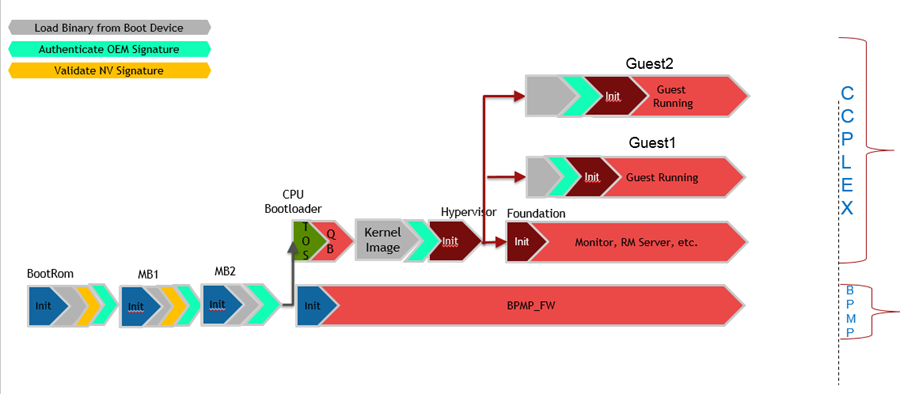
Upon power-up of the device, the boot flow sequence of events is as follows:
Notice that the BPMP processor runs:
• BootROM
• MB1
• MB2
• BPMP-FW
For details on the BPMP operation, consult the Technical Reference Manual for details.
BootROM
The BootROM is hard-wired in the Tegra chip to:
• Initialize the necessary registers to access the desired boot media.
• Loads the boot components as per the boot sequence.
The initial boot medium is selected using the strap resistor configuration BOOT-SELECT_CODE. Consult the Technical Reference Manual for your Tegra device for hardware configuration details.
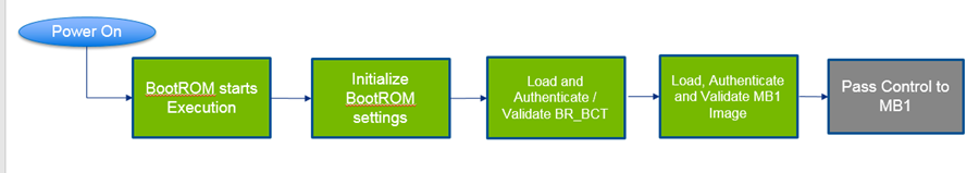
The bootROM flow sequence is as follows:
The BootROM uses a boot configuration table named BR_BCT, which contains information such as:
• MB1 storage location
• MB1 entrypoint
• Load address
• Validation refers to validating a binary against corruption using SHA256 or CMAC-Hash or other algorithm.
• Authentication refers to validating the authenticity of the binary using the secure key programmed in fuses. For authentication and validation information consult
Understanding Security. • BR_BCT is NOT customer configurable. Consult Technical Reference Manual for details.
Microboot 1
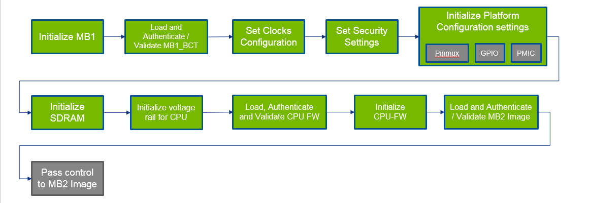
After the BootROM is successfully booted, Microboot1 (MB1) launches in the boot flow process as follows:
MB1 extends BootROM to provide the same security level. During MB1 sequence, these tasks are executed:
• Initialize the SDRAM based on the MB1 boot configuration table, MB1_BCT
• Set the security settings
• Configure pinmux/GPIO for the SoC
• Program the PMIC for the VDD_CPU and VDD_DDR rails
MB1_BCT is NOT customer configurable.
Microboot 2
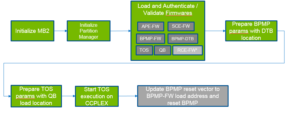
The next stage of the boot sequence is Microboot 2 (MB2). The sequence is as follows:
MB2 loads and validates additional firmware that configures the SoC to run more complex software components. The additional firmware components are as follows:
Firmware Component | Description |
Audio Processor Engine Firmware (APE-FW) | Provides the facilities for audio processing. |
Boot and Power Management Processor Firmware(BPMP-FW) | Manages the clock and power states of the SoC. |
Boot and Power Management Processor Device Tree Binary (BPMP-DTB) | Provides the device tree binary. |
Quickboot (QB) | Sets up the necessary environment to boot Hypervisor. |
Safety Engine Firmware(SCE-FW) | Provides the facilities for real-time camera processing with the safety firmware. |
Realtime Engine Firmware (RCE-FW) | Provides the realtime camera processing engine |
Authentication and Validation of Binaries
All binary firmware loaded by MB1 and MB2 are validated and optionally authenticated.
A Binary Component Header (BCH) contains information about the binaries in a binary group. It is attached to the top of each binary or can be attached to one binary in the binary group. Up to four binaries can belong to a group. A BCH has an array of four elements, which contain:
• Size of the binary
• Version number
• Hash value
For more information about BCH refer to
Grouping of Boot Images.
Dual Authentication of Firmware
MB1 firmware and CPU firmware are delivered in binary form and are signed with the NVIDIA and OEM RSA keys. As a result, two validation steps are required:
1. Authentication and validation with the OEM key
2. Authentication and validation with the NVIDIA key
Recovery Support
For authentication and validation information consult
Understanding Security.
SecureOS
The SecureOS (TOS) runs in EL3 mode and provides SecureMode support.
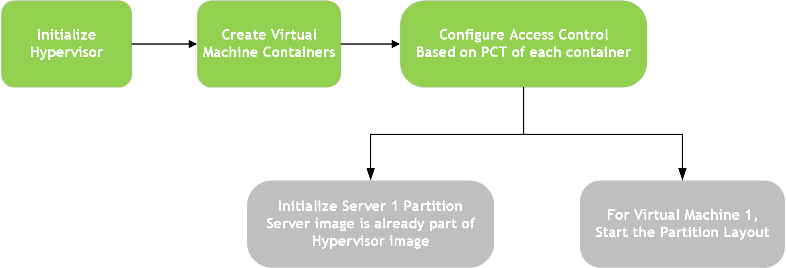
Hypervisor-based Flow
The hypervisor-based flow is as follows:
Virtual Machine
The Virtual Machine (VM) is an emulation of a native system. It is a software container that functions as an independent system with its own dedicated hardware and operating system, called guest OS in the context of Hypervisor.
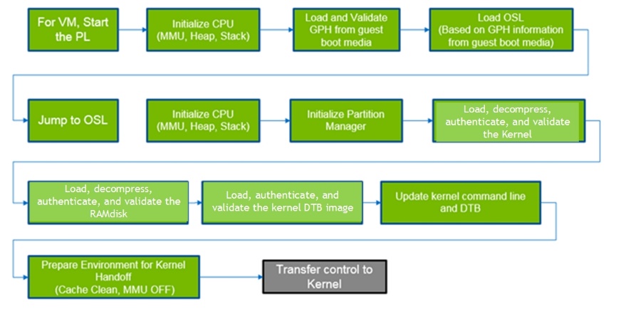
Partition Loader
The PartitionLoader (PL) is a special purpose boot loader image embedded into the Hypervisor. It acts as Virtual boot ROM for the virtual machine.
The Guest Partition Header (GPH), similar to the BCT, contains the information for the OSLoader load information, signature, size, etc.
OSLoader
The OSLoader (OSL) is the virtual BL-loader. It sets up the environment of the virtual machine.
The guest OS can be:
• Linux
• QNX
Grouping of Boot Images
Authenticating each boot firmware binary to maintain chain of trust requires a great deal of time. Consequently, for boot time optimization, a new mechanism to group boot binaries is provided. A minimum of one, and up to a maximum of four, binaries can be made to form a group and refer to a single header as Boot Component Header(BCH) for a group. BCH has sha256 checksum for each binary in the group. BCH is prepended to the binary that is loaded first in that group.
During boot, BCH is authenticated and firmware binaries in the group are hash validated. This mechanism helps avoid authentication time for individual binaries.
For best practices and good design, consider these limitations when grouping the boot binaries:
1. Firmware loaded by the same loader can form a group.
For example:
• Firmware loaded by OSL i.e. kernel, kernel-dtb and ramdisk can form a group.
• Firmware loaded by MB2 i.e. bpmp-fw, bpmp-dtb, cpu-bootloader can form a group.
• Firmware loaded by different loader cannot be part of a single group; the system cannot boot.
2. BCH must be prepended to the first binary loaded in the group. Consequently, the load order must be verified before grouping.
For example, if kernel, kernel-dtb and ramdisk are grouped together then BCH must be present on kernel.
3. Boot image partition under a group must be updated together.
4. Grouping of NVIDIA signed binaries such as MB1, MTS-Preboot, MTS-BootPack cannot be changed by the OEM.