Understanding NvMedia IPP Framework
The NVIDIA® Image Processing Pipeline (IPP) framework provides High Dynamic Range (HDR) camera processing for generating output images for human (HV) and machine (MV) vision. This content describes the details of NVIDIA IPP.
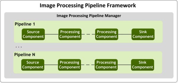
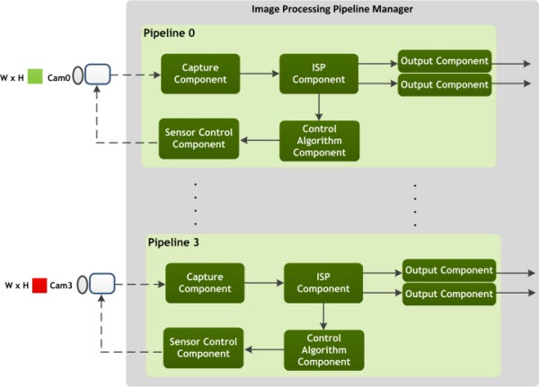
The IPP framework architecture consists of components that comprise component types for performing image processing. These components can be connected together to form a pipeline for end-to-end processing with a single camera. The IPP Manager is used to manage the multiple pipelines that are created.
The high-level IPP framework is as follows.
Components require image buffers and queues to send the processed images to the next component. Each component maintains a buffer pool to store the result of the processing done by the component. Depending on the component type, multiple buffer pools are required.
Additionally, multiple pipelines can be developed for each camera. The IPP Pipeline manager serves as the clearing house to manage the pipelines across all the cameras and ensures efficient image processing and communication.
The IPP framework is part of the NvMedia multimedia software stack. With the NvMedia software stack, applications leverage the NvMedia APIs to process image and video data.
IPP Component Types
The IPP components perform one image processing step in a pipeline. Components can have input and output ports. Through these ports, components transfer images, status, and control information to the next component in the pipeline.
Internally, components communicate with one another through message queues that are passed by the buffer. The result of the processing is stored in these buffer pools and associated with the component.
Components, based on their roles, consist of the following component types:
• Source components that includes capture and file reader components.
• Processing components that receive frames from their input ports, performs the processing and then sends the processed images to the output ports.
• Control Algorithm component that receives image statistics information, and performs the processing on the data.
• Sensor control components that receive sensor control information and sends it to the image sensor control component.
• Sink Components that receive frame information and provide the frame to the application.
Source Components
Source components acquire frames from a source. The source can be an image capture device such as Camera Serial Interface (CSI) or a file. Source components include:
• Capture component
• CaptureEx component
• File reader component
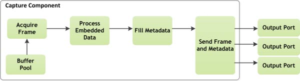
Capture Component
The capture component gets the related buffer from the buffer pool, and the capture device stores the images into the buffer. If the captured frame contains embedded line information, that information is parsed and stored as metadata. The component then sends the captured images to the output ports. Multiple output ports are available to support aggregated image captures. When an aggregated image is captured, the image contains images from multiple cameras. The component separates these images and outputs them using different output ports.
The capture component structure is as follows.
CaptureEx Component
The CaptureEx component functions similarly to the capture component, except that it uses virtual channels for the capture.
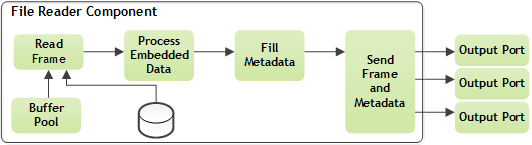
File Reader Component
The file reader component functions similarly to the capture component, but images are read from a file.
The file reader component structure is as follows.
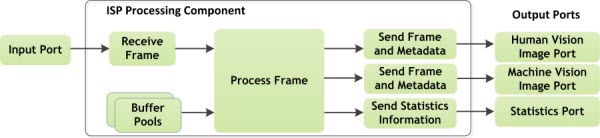
Processing Components
Processing components receive frames from their input port, perform the processing, such as Image Signal Processing (ISP), and send the processed images to the output ports. These processing components can have multiple output ports to provide various types of outputs, such as human and machine vision images, and image statistics information.
The ISP processing component structure is as follows.
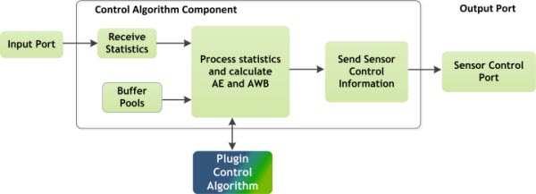
Control Algorithm Component
The control algorithm component receives image statistics information to perform auto exposure (AE) and auto white balance (AWB) processing on the received data. The processed data is output as sensor control information. To transmit that processed data, the control algorithm component calls the Plugin Control Algorithm (PCA) that is supplied by the application. The PCA receives all the statistics information and calculates the AE and AWB.
The control algorithm component structure.
Additionally, the control algorithm component can be attached to the Plugin Control Algorithm (Plugin) as a configuration option. See
IPP Plugin for more information.
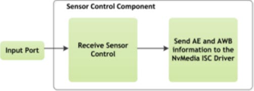
Sensor Control Components
The sensor control component receives sensor control information from the input port and sends that information to the image sensor using the NvMedia ISC driver.
The sensor control component structure is as follows.
Sink Components
Sink components receive frame information from the input port and provides the frame to the application. The sink component types include:
• Output component
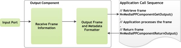
Output Component
The output component provides the frame to the application. The application can retrieve the frame using the NvMediaIPPComponentGetOutput function. This is a blocking call that waits until the frame is available. If the frame is not available within the specified timeout period, the API returns an error code indicating that it has timed out. When the application processes the frame is must return it using the NvMediaIPPComponentReturnOutput function.
The output component structure is as follows.
Ports
Components have input and output ports. When these ports are connected, components can communicate with each other sending buffers, status, and control information. In the IPP framework, the following port types are defined:
• NVMEDIA_IPP_PORT_IMAGE_1
The main type of port for sending images between components. The actual image type depends on the component.
• NVMEDIA_IPP_PORT_IMAGE_2
This port type is used for machine vision output.
• NVMEDIA_IPP_PORT_STATS_1
This port type is used to transfer ISP statistics information.
• NVMEDIA_IPP_PORT_SENSOR_CONTROL_1
This port type sends sensor exposure control information.
• NVMEDIA_IPP_PORT_IMAGE_CAPTURE_AGGREGATE
This port type is used only to connect the ICP component with an output component to export an aggregated image.
Buffer Pool
A buffer pool consists of a set of buffers used by components to store the result of the processing performed by the component. Depending on the component type, components can have multiple output ports. For each output port, a buffer pool is required.
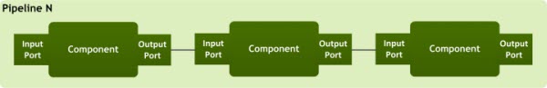
IPP Pipeline
The IPP framework accommodates up to 12 pipelines for Parker and up to 16 pipelines for Xavier. A pipeline is a set of components attached together to provide end-to-end processing from capture to processed human and machine vision images.
The high-level overview of a pipeline is as follows.
Depending on the component type, components can have multiple input and output ports to send information.
A typical pipeline includes the following structure with components, buffers as required for the component type, and the Plugin Control Algorithm which is a client installable set of APIs that can be added to the Control Algorithm (CA) component as a configuration option. Additionally, the image sensor is an external image device that can be programmed using NvMedia ISC APIs.
The typical pipeline structure is as follows.
Pipeline Manager
The Pipeline Manager manages device contexts and serves as the parent class for pipelines. Additionally, the IPP Manager:
• Can manage up to NVMEDIA_MAX_PIPELINES_PER_MANAGER pipelines.
• Sets up a common event callback mechanism for IPP components that are part of the manager.
• Manages timestamping of IPP components in the form of a client registered callback function.
Multiple IPP pipelines can be created and managed by the IPP Manager as follows.
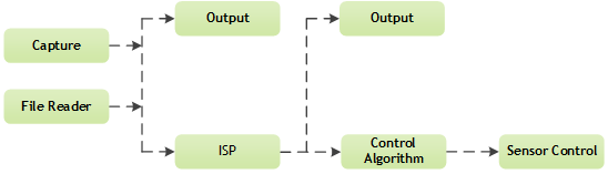
Component Connections
The IPP framework allows connections between the various component types. Components can be connected as defined in the following component attachment chart.
For example, a Capture component can attach to an output component directly, but the path for connecting to the Sensor Control component is via the Control Algorithm and ISP component. Likewise, the File Reader component can connect directly to the Output component, or via the ISP component, as defined by the arrow pathways.
When multiple components are attached to a component (for example, in the diagram Output and ISP are attached to Capture) IPP expects that both are continuously consuming the generated frames. If one of the components stops consuming, the source component runs out of its buffer pool and stops producing frames. This can cause pipeline stalling. IPP architecture does not support dynamic de-attachment from a component. If no further processing is required at a component level, frames should be consumed continuously and immediately returned using NvMediaIPPComponentReturnOutput() API.
IPP Plugin
The IPP framework supports the Plugin Control Algorithm (referred to as Plugin) that can be added to the Control Algorithm (referred to as Parent component) as a configuration option. The plugin, executed on a frame-by-frame basis, performs the following functions:
• Auto exposure control (AE)
• Auto white balance control (AWB)
• High dynamic range (HDR) ratio calculation
• Set histogram and LAC statistics configuration
Installing the Plugin
Install the plugin by populating the function pointers in the pluginFuncs structure that is part of the Control Algorithm component configuration NvMediaIppControlAlgorithmComponentConfig.
If a plugin is not provided, by setting the pluginFuncs to NULL, the IPP framework uses doesn’t control the exposure or white balance gains.
typedef struct
{
NvMediaIPPluginCreateFunc *createFunc;
NvMediaIPPPluginDestroyFunc *destroyFunc;
NvMediaIPPluginProcessExFunc *processExFunc;
} NvMediaIPPPluginFuncs;
Structure Members
Member | Description |
createFunc | A pointer for the create-plugin function. The function is called during the creation of the parent Control Algorithm. |
destroyFunc | A pointer for the destroy-plugin function. The function is called if the parent Control Algorithm is destroyed. |
processExFunc | A pointer for the process plugin function. The function is called for every frame by the parent Control Algorithm to process the image statistics and generate the control results for future images. This function used for both continuous Exposure and bracketed exposure mode. |
Plugin API Functions
The plugin must implement the functions described in “Structure Members”. You can choose any names for the functions because only the addresses of the functions are required.
CreateFunction
The create function is called when the parent component is created in the context of the application thread creating the parent component. The plugin must allocate its own context to store any state information it requires. The plugin create function receives the handle of the parent component, which the plugin must store for callbacks to the parent component. The callback functions that the plugin can call are passed in the supportFunctions structure.
For more information, see the NvMediaIPPPluginSupportFuncs structure in the nvmedia_ipp.h file.
When the plugin is finished with the create function, it must pass back its own handle with the pluginHandle parameter.
The-plugin create function also receives a set of static properties with the staticProperties parameter. Those properties describe the properties that do not change during the lifetime of the plugin.
Declaration
NvMediaStatus CreateFunc(
NvMediaIPPComponent *parentControlAlgorithmHandle,
NvMediaIPPPluginSupportFuncs *supportFunctions,
NvMediaIPPPropertyStatic *staticProperties,
void *clientContext,
NvMediaIPPPlugin **pluginHandle,
NvMediaIPPISPVersion ispVersion);
Parameters
Parameter | Description |
parentControlAlgorithmHandle | Specifies the handle of the parent Control Algorithm. |
supportFunctions | Specifies the functions that the plugin can call. |
staticProperties | Specifies the properties that do not change during the lifetime of the plugin. |
clientContext | Specifies the client context passed to the plugin. |
pluginHandle | Specifies the plugin’s handle filled by the plugin. |
ispVersion | Specifies the IPP ISP version |
Returns
Value | Description |
NVMEDIA_STATUS_OK | Success |
NVMEDIA_STATUS_ERROR | An error occurred. |
DestroyFunction
The destroy function destroys a plugin. This function is called when the parent component is destroyed in the context of the application thread destroying a parent component. The function receives its own handle through the pluginHandle parameter. The plugin must free any memory it allocated and destroy the handle.
Declaration
void DestroyFunc(
NvMediaIPPPlugin *pluginHandle);
Parameters
Parameter | Description |
pluginHandle | Specifies the plugin handle to be destroyed. |
ProcessExFunction
The process function is called the first time the parent component is created in the context of the application thread creating a parent component. Subsequently, that function is called when the ISP has processed the captured image and generated the statistics in the context of the thread of the parent component.
This function is called at capture speed, one call per image. The plugin receives input information in the
pluginInput structure and puts the results into the
pluginOutput structure. For the first time, when this function is called
firstRun flag is set to
NVMEDIA_TURE and apart from
controlsProperties, other members of
pluginInput are null or invalid.
NvMediaIPPPluginInput and
NvMediaIPPPluginOutputEx structures are described in
Input and Output Parameters for the Plugin. This function is used for bracketed exposure control and continuous exposure control by setting the
useBracketedExp flag in
pluginOutput.
Note: | The changing between bracketed and continuous exposure mode is not allowed dynamically. |
Declaration
NvMediaStatus ProcessExFunc(
NvMediaIPPPlugin *pluginHandle,
NvMediaIPPPluginInput *pluginInput,
NvMediaIPPPluginOutputEx *pluginOutput);
Parameters
Parameter | Description |
pluginHandle | Specifies the plugin handle. |
pluginInput | Specifies the input parameters to the plugin. |
pluginOutput | Specifies the generated output parameters by the plugin. |
Returns
Value | Description |
NVMEDIA_STATUS_OK | Success |
NVMEDIA_STATUS_ERROR | An error occurred. |
Plugin Callback
At creation time, the plugin receives a set of function pointers. These are support functions that the plugin can call.
Currently there is only support function which is to get the sensor attributes like minimum & maximum sensor gain and exposure time.
Declaration
typedef NvMediaStatus NvMediaIPPGetSensorAttr(
NvMediaIPPComponent *parentControlAlgorithmHandle,
NvMediaISCSensorAttrType type,
uint32_t size,
void *attribute);
Parameters
Parameter | Description |
parentControlAlgorithmHandle | Specifies the parent Control Algorithm handle that was received during the creation of the plugin. |
type | Sensor attribute type |
size | Size of the attribute |
attribute | Sensor attribute value |
Stream Types
The ISP component can produce two streams of images from its input images. The input parameters of the plugin contain the stream data for each stream. Likewise, plugin output contains the settings for each stream.
Input Parameters
When the plugin process function is called, it must process the input information and generate the output parameters. The Control Algorithm component fills the input information before calling ProcessFunction and applies all valid output settings after ProcessFunction returns.
The plugin receives information in the following categories:
• Image information
• Control properties
• Exposure control
• White balance control
• Embedded line information
• Histogram and LAC statistics
• Flicker band statistics
NvMediaIPPPluginInput
The input information is passed according to the following structure:
typedef struct
{
NvMediaIPPImageInformation imageInfo;
NvMediaIPPPropertyControls *controlsProperties;
NvMediaISCExposureControl exposureControl;
NvMediaISCWBGainControl whiteBalanceGainControl[2];
NvMediaISCEmbeddedDataBuffer topEmbeddedData;
NvMediaISCEmbeddedDataBuffer bottomEmbeddedData;
NvMediaIPPPluginInputStreamData
streamData[NVMEDIA_IPP_STREAM_MAX_TYPES];
NvMediaBool firstRun;
float_t brightness;
} NvMediaIPPPluginInput;
Structure Members
Member | Description |
imageInfo | Specifies generic information such as: • Frame ID • Camera ID • Capture timestamp • frame-sequence count |
controlsProperties | Specifies the properties that contain information to control the behavior of the plugin. The control properties are set by the parent Control Algorithm but can be changed by the client application. It can enable or disable certain features and set processing parameters and modes. |
exposureControl | Specifies the exposure control parameters that are applied on the currently processed frame. |
whiteBalanceGainControl[2] | Specifies the white balance control parameters that are applied on the currently processed frame. whiteBalanceGainControl[0] is associated with sensor or before hdr merge and whiteBalanceGainControl[1] is associated with ISP after hdr merge |
topEmbeddedData | Specifies the top embedded lines associated with the currently processed frame. |
bottomEmbeddedData | Specifies the bottom embedded lines associated with the currently processed frame. |
streamData | Specifies an array of statistics data for the various streams. |
firstRun | When the plugin algorithm is called the first time it is done from the Control Algorithm’s create function and this flag is set to NVMEDIA_TRUE. During normal operation, this flag is set to NVMEDIA_FALSE. Note: When this flag is set, the statistics pointers in the streamData structure member are set to NULL. |
brightness | Specifies the brightness value calculated by IPP framework for the frame associated with plugin Input for use in plugin |
imageInfo
The imageInfo structure member contains information on the image that is being processed.
The definition is as follows:
typedef struct {
uint32_t frameId;
uint32_t cameraId;
NvMediaGlobalTime frameCaptureGlobalTimeStamp;
uint32_t frameSequenceNumber;
} NvMediaIPPImageInformation;
Member | Description |
frameId | Specifies a unique frame ID used internally by the NvMedia IPP. |
cameraId | Specifies the ID of the camera that generated the image in the pipeline. |
frameCaptureGlobalTimeStamp | Specifies the capture timestamp of the image using global time in microseconds. |
frameSequenceNumber | Specifies a continuously increasing frame number that is unique within a pipeline. |
controlsProperties
The controlsProperties structure member, set by the client application, controls the behavior of the plugin.
The definition is as follows:
typedef struct
{
NvMediaBool manualAE;
NvMediaISCExposureControl exposureControl;
NvMediaBool manualAWB;
NvMediaISCWBGainControl wbGains;
NvMediaIPPAeAntiFlickerMode aeAntiFlickerMode;
float_t ispDigitalGain;
} NvMediaIPPPropertyControls;
Member | Description |
manualAE | Controls the plugin’s auto exposure mode. If this parameter is set to NVMEDIA_FALSE, the plugin must perform auto exposure control. If this parameter is set to NVMEDIA_TRUE, the plugin applies the pre-calculated values saved in exposureControl. |
exposureControl | Specifies the exposure-control values set by the client application in case manualAE is set to NVMEDIA_TRUE. |
manualAWB | Controls the plugin’s white balance mode. If this parameter is set to NVMEDIA_FALSE, the plugin must perform auto white balance control. If this parameter is set to NVMEDIA_TRUE, the plugin applies the pre-calculated white balance gains saved in wbGains. |
wbGains | Specifies the white balance gains values set by the client application. These values are used for white balance if manualAWB is set to NVMEDIA_TRUE. |
aeAntiFlickerMode | Contains the anti-flicker mode the plugin uses for calculating the exposure time. The plugin must choose an exposure time that minimizes the time aliasing or beating effect on the captured images. The following modes are supported: • NVMEDIA_IPP_AE_ANTI_FLICKER_MODE_OFF
The plugin does not need to perform any flicker mode-related calculations. • NVMEDIA_IPP_AE_ANTI_FLICKER_MODE_50Hz
The plugin assumes that the prevalent light sources are 50Hz. • NVMEDIA_IPP_AE_ANTI_FLICKER_MODE_60Hz
The plugin assumes that the prevalent light sources are 60Hz. NVMEDIA_IPP_AE_ANTI_FLICKER_MODE_AUTO
The plugin must analyze the flicker band statistics and calculate the proper exposure time. |
ispDigitalGain | Digital gain performed by the ISP. |
exposureControl
The exposureControl structure member provides information on the exposure of the image that is being processed.
The definition is as follows:
typedef struct NvMediaISCExposureControl {
struct {
float_t value;
NvMediaBool valid;
} exposureTime[NVMEDIA_ISC_EXPOSURE_MODE_MAX];
struct {
float_t value;
NvMediaBool valid;
} sensorGain[NVMEDIA_ISC_EXPOSURE_MODE_MAX];
unsigned char sensorFrameId;
} NvMediaISCExposureControl;
Member | Description |
exposureTime | Specifies the exposure time for each exposure mode. There are three exposure modes: • Long • Short • Very short The exposure time for each mode is represented by an array element indexed with the following values: • NVMEDIA_ISC_EXPOSURE_MODE_LONG • NVMEDIA_ISC_EXPOSURE_MODE _SHORT • NVMEDIA_ISC_EXPOSURE_MODE_VERY_SHORT |
exposureTime.valid | A flag that indicates that the exposure time is valid for the exposure mode. |
exposureTime.value | Specifies the exposure time, in seconds, for the exposure mode. |
sensorGain | Specifies the sensor-gain values for each exposure mode. A sensor gain is a multiplier that controls the sensor’s pixel value amplification. At sensor level, this sensor gain is separated to analog and digital gain. There are three exposure modes: • Long • Short • Very short The sensor gain for each mode is represented by an array element indexed with the following values: • NVMEDIA_ISC_EXPOSURE_MODE_LONG • NVMEDIA_ISC_EXPOSURE_MODE_SHORT • NVMEDIA_ISC_EXPOSURE_MODE_VERY_SHORT |
sensorGain.valid | A flag that indicates that the sensor gain is valid for the exposure mode. |
sensorGain.value | Specifies the sensor gain for the exposure mode. |
whiteBalanceGainControl
The wbGains structure member provides information on the white balance gains of the image that is being processed.
The definition is as follows:
typedef struct NvMediaISCWBGainControl {
struct {
float_t value[4];
NvMediaBool valid;
} wbGain[NVMEDIA_ISC_EXPOSURE_MODE_MAX];
} NvMediaISCWBGainControl;
Member | Description |
wbGain | Specifies the white balance gains for each exposure mode. There are three exposure modes: • Long • Short • Very short The exposure time for each mode is represented by an array element indexed with the following values: • NVMEDIA_ISC_EXPOSURE_MODE_LONG • NVMEDIA_ISC_EXPOSURE_MODE_SHORT • NVMEDIA_ISC_EXPOSURE_MODE_VERY_SHORT |
wbGain.valid | A flag that indicates that the white balance gains are valid for the exposure mode. |
wbGain.valid[4] | An array of gains for each Bayer color channel in order R, Gr, Gb, and B. |
topEmbeddedData & bottomEmbeddedData
The topEmbeddedData & bottomEmbeddedData structure members provide embedded lines data for the image that is being processed. The embedded-line data is compacted; the marker and duplicate bytes are removed. That information is a set of registers of the image sensor. The base address register value corresponds to the first byte of the embedded data in the memory.
The definition is as follows:
typedef struct {
uint32_t baseRegAddress;
uint32_t size;
uint32_t bufferSize;
uint8_t *data;
} NvMediaISCEmbeddedDataBuffer;
Member | Description |
baseRegAddress | Specifies the base register address that corresponds to the first byte of embedded line data. |
size | Specifies the size of the embedded line data captured from the image sensor. |
bufferSize | Specifies the allocation size of data. |
data | A pointer to the embedded line data. |
streamData
This structure contains the statistics data for each type of stream. The structure includes a union member in which v4 is defined for the Parker platform and v5 is defined for the NVIDIA DRIVE™ AGX Xavier Platform.
typedef struct
{
NvMediaBool enabled;
union {
struct {
NvMediaISPStatsHistogramMeasurement
*histogramStats[2];
NvMediaISPStatsLacMeasurementV4
*lacStats[2];
NvMediaISPStatsFlickerBandMeasurement
*flickerBandStats;
} v4;
struct {
NvMediaISPStatsHistogramMeasurementV5
*histogramStats[2];
NvMediaISPStatsLacMeasurementV5
*lacStats[2];
NvMediaISPStatsFlickerBandMeasurementV5
*flickerBandStats;
} v5;};
} NvMediaIPPPluginInputStreamData;
Member | Description |
enabled | If true, specifies that the corresponding stream is enabled. Otherwise, the corresponding stream is disabled and the statistics for this stream are not available. |
histogramStats | An array of two pointers to histogram statistics. Two histogram statistics correspond to the two histogram statistics units in the ISP. The first histogram unit generates statistics from Bayer domain pixels; the second one is from RGB domain pixels. If the Control Algorithm component fails to retrieve histogram statistics for one histogram statistics unit, the corresponding pointer is NULL. |
lacStats | An array of two pointers to Local Average and Clipping (LAC) statistics information. Two LAC statistics correspond to the two LAC statistics units in the ISP. Both units generate statistics from the Bayer domain. Each pointer might be NULL if the statistics are not available. |
flickerBandStats | A pointer to the flicker band statistics. The pointer is NULL if the Control Algorithm component fails to get those statistics. |
histogramStats
The histogramStats structure member provides histogram information for the image that is being processed. Histogram information is divided into bins. Each bin represents a count that was calculated by counting the number of pixels that fell into the bin’s range. Typically, there are 256 bins for each color component. For different color component modes, the number of color components varies.
The structure for the Parker platform (v4) is defined as follows:
typedef struct {
unsigned int numBins;
unsigned int *data[NVMEDIA_ISP_COLOR_COMPONENT_NUM];
} NvMediaISPStatsHistogramMeasurement;
Member | Description |
numBins | Specifies the number of bins contained in the histogram for each color component. All color components have the same number of bins. |
Data | An array of pointers to the histogram information. Each pointer points to a memory array that has numBins elements of histogram information. The array size is determined by the color-component mode of the histogram. For Bayer statistics, there are four components and the array is in order R, Gr, Gb, and B Bayer color channel. For RGB color components, and the array is in order R, G, and B. The second histogram is calculated in the RGB domain before gamma is applied. |
The structure for DRIVE AGX Xavier Platform (v5) is defined as follows:
typedef struct {
uint32_t histData[NVMEDIA_ISP5_HIST_BIN_COUNT]
[NVMEDIA_ISP_COLOR_COMPONENT_NUM];
uint32_t excludedCount[NVMEDIA_ISP_COLOR_COMPONENT_NUM];
} NvMediaISPStatsHistogramMeasurementV5;
Member | Description |
histData | An array of pointers to the histogram information. Each pointer points to a memory array that has numBins elements of histogram information. The size of the array is determined by the color-component mode of the histogram. For Bayer statistics, there are four components and and the array is in order R, Gr, Gb, and B Bayer color channel. For RGB color components, and the array is in order R, G, and B. The second histogram is calculated in the RGB domain before gamma is applied |
excludedCount | Specifies the number of excluded pixels for each color component. |
lacStats
The lacStats structure member provides Local Average and Clipping (LAC) information for the image that is being processed. The LAC information is computed by using a number of windows over the image and calculating the average pixel values within those windows. When the LAC statistics are configured, the number and the position of the windows are defined at that time. The lower and upper limits of pixel values are also defined. The pixel values not falling into the range are not used in the average calculations. These averages are provided on a color-component basis. For different color component modes, the number of color components varies.
The structure for the Parker platform (v4) is defined as follows:
typedef sruct {
NvMediaBool ROIEnable[NVMEDIA_ISP_LAC_ROI_NUM];
NvMediaISPPoint startOffset[NVMEDIA_ISP_LAC_ROI_NUM];
NvMediaISPSize windowSize[NVMEDIA_ISP_LAC_ROI_NUM];
unsigned int numWindows[NVMEDIA_ISP_LAC_ROI_NUM];
unsigned int numWindowsH[NVMEDIA_ISP_LAC_ROI_NUM];
unsigned int numWindowsV[NVMEDIA_ISP_LAC_ROI_NUM];
float *average[NVMEDIA_ISP_LAC_ROI_NUM][NVMEDIA_ISP_COLOR_COMPONENT_NUM];
unsigned int *numPixels[NVMEDIA_ISP_LAC_ROI_NUM][NVMEDIA_ISP_COLOR_COMPONENT_NUM];
} NvMediaISPStatsLacMeasurementV4;
Member | Description |
ROIEnable | Specifies whether a ROI is enabled or not. If a ROI is disabled ignore the measurement values corresponding to that ROI. Reading values for disabled ROI will give undefined values. |
startOffset | Holds the position of the top-left pixel in the top-left window. |
windowSize | Specifies the size of each ROI measurement window in pixels. |
numWindows | Holds the number of windows in LAC statistics. Must be greater than or equal to (NumWindowsH * NumWindowsV). |
numWindowsH | Holds the number of windows in the horizontal direction. |
numWindowsV | Holds the number of windows in the vertical direction |
average | For each ROI, a list of pointers, each of which points to a memory array with numWindows elements of average information. For each window, the value is the average of pixel values that are within the configured pixel value range. Both of the LAC statistics are in the Bayer domain. The array is in order R, Gr, Gb, and B Bayer color channel. |
numPixels | Holds the number of pixels per ROI per component. |
The structure for DRIVE AGX Xavier Platform (v5) is defined as follows:
typedef struct
{
NvMediaBool ROIEnable[NVMEDIA_ISP_LAC_ROI_NUM];
NvMediaISPSize windowSize[NVMEDIA_ISP_LAC_ROI_NUM];
NvMediaISPStatsLacROIDataV5
ROIData[NVMEDIA_ISP_LAC_ROI_NUM];
} NvMediaISPStatsLacMeasurementV5 ;
Member | Description |
ROIEnable | Specifies whether an ROI is enabled or not. If an ROI is disabled ignore the measurement values corresponding to that ROI. Reading values for a disabled ROI gives undefined values. |
windowSize | Holds the size of each ROI measurement window in pixels. |
ROIData | For each ROI a list of pointers, each of which points to an array that has numWindows elements of average information. For each window, the value is the average of pixel values within the configured pixel value range. Both of the LAC statistics are in the Bayer domain. The array is in order R, Gr, Gb, and B Bayer color channel. |
flickerBandStats
The flickerBandStats structure member provides flicker-band information for the image that is being processed. The flicker-band information is calculated by using a number of windows over the image and taking the average luminance of the pixel values within those windows. When the flicker band statistics are configured, the number and the position of the windows are defined at that time. The windows are defined as a matrix, but for the flicker information, the horizontal number of windows is one.
The structure for the Parker platform (v4) is defined as follows:
typedef struct
{
unsigned int numWindows;
int_*luminance;
} NvMediaISPStatsFlickerBandMeasurement;
Member | Description |
numWindows | Specifies the number of windows for average luminance calculation. |
Luminance | A pointer to an array of luminance averages. It contains an array of numWindows elements, each value corresponding to a window. |
The structure for the DRIVE AGX Xavier Platform (v5) is defined as follows:
typedef struct
{
unsigned int numWindows;
float_t_luminance[NVMEDIA_ISP5_FB_WINDOWS];
} NvMediaISPStatsFlickerBandMeasurementV5;
Member | Description |
numWindows | Specifies the number of windows for average luminance calculation. |
luminance | An array that points to the luminance averages. It points to an array of numWindows elements, each value corresponding to a window. |
Output Parameters
When the plugin process function is called, it must process the input information and generate the output parameters. The Control Algorithm component fills the input information before calling ProcessFunction and applies all valid output settings after ProcessFunction returns.
The plugin must generate the information in the following categories:
• Exposure control
• White balance control
• Histogram statistics settings
• LAC statistics settings
• Flicker-band statistics settings
NvMediaIPPPluginOutputEx
The NvMediaIPPPluginOutputEx structure is provides the ISP stats settings , exposure settings, and whitebalance settings calculated by plugin based on the ISP stats received in Plugin Input.
The output is passed according to the following structure:
typedef struct
{
NvMediaBool useBracketedExp;
NvMediaIPPAeState aeState;
uint32_t numExposureControl;
NvMediaISCExposureControl
exposureControl[NVMEDIA_IPP_MAX_EXPOSURE_SETS];
NvMediaIPPAwbState awbState;
NvMediaISCWBGainControl whiteBalanceGainControl[2];
NvMediaIPPMathFloatMatrix colorCorrectionMatrix;
NvMediaIPPMathFloatMatrix colorCorrectionsMatrixRec2020;
float_t ispDigitalGain;
NvMediaIPPPluginOutputStreamSettings
streamSettings[NVMEDIA_IPP_STREAM_MAX_TYPES];
float_t awbCCT;
} NvMediaIPPPluginOutputEx;
Member | Description |
useBracketedExp | Specifies the exposure control mode: Plugin shall set this flag to NVMEDIA_TRUE for bracketed exposure control and NVMEDIA_FALSE for continuous exposure control |
aeState | Specifies the state of the plugin’s internal auto exposure algorithm. The following states are defined: • NVMEDIA_IPP_AE_STATE_INACTIVE • NVMEDIA_IPP_AE_STATE_SEARCHING • NVMEDIA_IPP_AE_STATE_CONVERGED • NVMEDIA_IPP_AE_STATE_TIMEOUT |
numExposureControl | Number of valid exposure-control parameters sets in the array |
exposureControl
[NVMEDIA_IPP_MAX_EXPOSURE_SETS] | Array of exposure-control parameters sets that are calculated according to the input information by the plugin. exposureControl[0] will be only used if the useBracketedExp flag is set to false. |
awbState | Specifies the state of the plugin’s internal auto white balance algorithm. The following states are defined: • NVMEDIA_IPP_AWB_STATE_INACTIVE • NVMEDIA_IPP_AWB_STATE_SEARCHING • NVMEDIA_IPP_AWB_STATE_CONVERGED • NVMEDIA_IPP_AWB_STATE_TIMEOUT |
whiteBalanceGainControl[2] | The white balance control parameters that are calculated by plugin according to the input information. whiteBalanceGainControl[0] is to apply in sensor or before hdr merge and whiteBalanceGainControl[1] is to apply in ISP after hdr merge. |
colorCorrectionMatrix | The color correction matrix to be applied. |
colorCorrectionsMatrixRec2020 | The color correction matrix to be applied if the output format is rec2020. |
ispDigitalGain | Digital gain to be applied in ISP. |
streamSettings | An array of statistics settings for different types of stream. |
awbCCT | Specifies the CCT based on AWB gains calculated by plugin. |
streamSettings
The streamSettings contains the statistics settings for each stream. This structure contains a union with elements for Parker (v4) and Xavier (v5).
The structure is defined as follows:
typedef struct
{
union {
struct {
NvMediaBool histogramSettingsValid[2];
NvMediaISPStatsHistogramSettingsV4
histogramSettings[2];
NvMediaBool lacSettingsValid[2];
NvMediaISPStatsLacSettingsV4 lacSettings[2];
NvMediaBool flickerBandSettingsValid;
NvMediaISPStatsFlickerBandSettingsV4
flickerBandSettings;
} v4;
struct {
NvMediaBool histogramSettingsValid[2];
NvMediaISPStatsHistogramSettingsV5
histogramSettings[2];
NvMediaBool lacSettingsValid[2];
NvMediaISPStatsLacSettingsV5 lacSettings[2];
NvMediaBool flickerBandSettingsValid;
NvMediaISPStatsFlickerBandSettingsV5
flickerBandSettings;
} v5;
};
} NvMediaIPPPluginOutputStreamSettings;
Member | Description |
histogramSettingsValid | An array of flags that validates the histogram settings. Set NVMEDIA_TRUE if the plugin contains a new histogram settings. Otherwise, set it to NVMEDIA_FALSE. |
histogramSettings | An array of histogram settings, which are valid only if the histogramSettingsValid flags are set to NVMEDIA_TRUE. Two histogram settings correspond to the two histogram statistics units in the ISP. The first histogram unit generates statistics for Bayer domain pixels; the second one is for the RGB domain pixels. |
lacSettingsValid | An array of flags that validate the LAC settings. Set to NVMEDIA_TRUE if the plugin contains a new LAC settings. Otherwise, set it to NVMEDIA_FALSE. |
lacSettings | An array of LAC settings. These are valid only if the lacSettingsValid flags are set to NVMEDIA_TRUE. Two LAC settings correspond to the two LAC statistics units in the ISP. Both LAC units are generating statistics for Bayer Domain. |
flickerBandSettingsValid | A flag that validates the flicker-band settings. Set to NVMEDIA_TRUE if the plugin contains a new flicker band settings. Otherwise, set it to NVMEDIA_FALSE. |
flickerBandSettings | The flicker-band settings, which are valid only if the flickerBandSettingsValid flag is set to NVMEDIA_TRUE. |
Note: | As an illustration, a sample implementation of the plugin is in the NvMedia IPP test application. The sample includes simple AE and AWB algorithms that demonstrate the functionality of the plugin with the NvMedia IPP framework. |
IPP Internals
This topic contains supplementary materials for the IPP framework.
NvMedia IPP API Description
The NvMedia Image Processing Pipeline API functionality is described as follows.
NvMediaIPPGetVersionInfo
Returns the version information on the NvMedia IPP library.
Declaration
NvMediaIPPStatus
NvMediaIPPGetVersionInfo(
NvMediaIPPVersionInfo *versionInfo);
Parameters
Function | Description |
versionInfo | Identifies the version information filed by the function. |
Returns
Function | Return |
NVMEDIA_STATUS_OK | Success |
NVMEDIA_STATUS_BAD_PARAMETER | Invalid input pointer |
Structure
The version information structure is as follows:
typedef struct {
NvMediaVersion libVersion;
} NvMediaIPPVersionInfo;
Function | Description |
libVersion | Identifies the version information on the NvMedia IPP library. |
Version Structure
• The NvMedia version structure as defined in the nvmedia_core.h is as follows:
typedef struct {
uint8_t major;
uint8_t minor;
} NvMediaVersion;
Function | Description |
major | Identifies the major version number. |
minor | Identifies the minor version number. |
NvMediaIPPManagerCreate
Creates an IPP manager object. The object is a container for all the pipelines created with its handle.
Declaration
NvMediaIPPManagerCreate(
uint32_t versionInfo,
NvMediaDevice *device);
Parameters
Function | Description |
versionInfo | Identifies the version information filed by the function. The client application must set this parameter to NVMEDIA_IPP_VERSION_INFO. The NvMedia IPP library uses this information to determine which version of the API the client application was compiled with. If the client application and NvMedia IPP library have different version numbers, the function returns NULL. The client application must be recompiled with the latest library and header files. |
device | Identifies the NvMedia device created by the NvMediaDeviceCreate function. |
Returns
Returns the handle of the new IPP manager, or returns NULL if unsuccessful.
NvMediaIPPManagerDestroy
Destroys an IPP manager object. It also destroys all the pipelines created with the IPP manager handle.
Declaration
void
NvMediaIPPManagerDestroy(
NvMediaIPPManager *ippManager);
Parameters
Function | Description |
ippManager | Identifies the IPP manager handle to be destroyed. |
NvMediaIPPManagerSetTimeSource
NvMedia IPP does not have access to an internal time source that is sufficient for absolute global time-stamping. The client application can establish a callback function to provide an absolute global time. When a frame is received by the capture component, it calls this function to get the absolute global time and stores this timestamp to the image. The NvMediaIPPManagerSetTimeSource function can be called after the NvMedia IPP manager is created. If the application does not establish a callback function, NvMedia IPP uses the kernel based timestamp obtained from the ktime_get_ts function to get the clock monotonic time.
The time format is a 64-bit unsigned value in microseconds. NvMediaGlobalTime is a typedef of type unsigned long. It is the responsibility of the client application to provide a reliable and accurate time value suitable for image capture timestamping.
Declaration
NvMediaStatus
NvMediaIPPManagerSetTimeSource(
NvMediaIPPManager *ippManager,
void *clientContext,
NvMediaStatus (* getAbsoluteGlobalTime)(
void *clientContext,
NvMediaGlobalTime *timeValue));
Parameters
Function | Description |
ippManager | Identifies the handle associated with this time source. |
clientContext | Defines the context of the caller application. If not required, set to NULL. |
getAbsoluteGlobalTime | A pointer to the function that returns the absolute global time. |
Returns
Value | Description |
NVMEDIA_STATUS_OK | Success |
NVMEDIA_STATUS_ERROR | An error occurred. |
getAbsoluteGlobalTime
The getAbsoluteGlobalTime callback function is defined as follows.
Declaration
NvMediaStatus GetAbsoluteGlobalTime(
void *clientContext,
NvMediaGlobalTime *timeValue);
Parameters
Function | Description |
clientContext | Identifies the context value passed when the NvMediaIPPManagerSetTimeSource function is called. |
timeValue | Writes the absolute global time pointed by the timeValue parameter defined in microseconds. |
Returns
Value | Description |
NVMEDIA_STATUS_OK | Success |
NVMEDIA_STATUS_ERROR | An error occurred while getting the time and the acquired time is invalid. |
NvMediaIPPManagerSetEventCallback
The NvMediaIPPManagerSetEventCallback function sets the event callback function which is called whenever an event occurs.
Note: | The event callback is called from the thread context of an NvMedia IPP component. Therefore, the called function cannot perform any blocking call and the overall processing must be kept to a minimum. |
NvMediaIPPManagerSetEventCallbackcan be called after the NvMedia IPP manager is created.
For more information, see the eventType parameter in the parameters table for the event callback function, below.
Parameters
Function | Description |
ippManager | Identifies the IPP manager handle that is associated with this time source. |
clientContext | Identifies the context of the caller application. If not required, set to NULL. |
eventCallback | A pointer to a callback function. |
Returns
Value | Description |
NVMEDIA_STATUS_OK | Success |
NVMEDIA_STATUS_ERROR | An error occurred. |
Event callback Function
The event callback function is defined as follows.
Declaration
void NvMediaIPPEventCallback(
void *clientContext,
NvMediaIPPComponentType componentType,
NvMediaIPPComponent *ippComponent,
NvMediaIPPEventType eventType,
NvMediaIPPEventData *eventData);
Parameters
Parameter | Description |
clientContext | Identifies the context value passed when the NvMediaIPPManagerSetEventCallback() function is called. |
componentType | Specifies the type of component that handles the callback. |
ippComponent | Specifies the component handle that manages the callback. |
eventType | Specifies the type of event. Event types can be one of the following: • NVMEDIA_IPP_EVENT_INFO_EOF
An obsolete event used by the former file writer component. • NVMEDIA_IPP_EVENT_INFO_PROCESSING_DONE
Specifies the processing-done event. This is called from the ISC, ISP, and Control Algorithm component at the end of the processing of one frame. • NVMEDIA_IPP_EVENT_INFO_FRAME_CAPTURE
Specifies the frame-capture event. This is called from the ICP component after every new frame capture. • NVMEDIA_IPP_EVENT_WARNING_CAPTURE_FRAME_DROP
Specifies the frame-drop event. This is called from the capture component whenever a frame drop is detected. • NVMEDIA_IPP_EVENT_ERROR_INTERNAL_FAILURE
Specifies an internal-failure error event. This event can be called from any component. • NVMEDIA_IPP_EVENT_ERROR_I2C_TRANSMISSION_FAILURE
Specifies that the sensor control component has detected an I2C transmission error. • NVMEDIA_IPP_EVENT_WARNING_CSI_FRAME_DISCONTINUITY
Specifies that the frame counter in the image embedded data is not continuous. • NVMEDIA_IPP_EVENT_ERROR_CSI_INPUT_STREAM_FAILURE Specifies that the CSI-RX detected an error in CSI input stream. eventData.captureErrorInfo has the error details. |
eventData | Indicates the event data associated with the event. The value can be NULL for some events. The application must verify before using this parameter. It contains the image information NvMediaIPPImageInformation. |
eventData
The eventData structure member provides information for the associated event and contains the frame drop control. The definition is as follows:
typedef struct {
NvMediaIPPImageInformation imageInformation;
NvMediaICPErrorInfo captureErrorInfo;
} NvMediaIPPEventData;
Function | Description |
imageInformation | Specifies the image information associated with the event. This information is NOT populated for all event types. |
captureErrorInfo | Specifies the capture error details. |
NvMediaIPPPipelineCreate
Creates the IPP pipeline.
Declaration
NvMediaIPPPipeline *
NvMediaIPPPipelineCreate(
NvMediaIPPManager *ippManager);
Parameters
Function | Description |
ippManager | Specifies the IPP manager handle associated with the pipeline. |
Returns
Specifies the new handle for the IPP pipeline; or NULL if unsuccessful.
NvMediaIPPPipelineSetProperties
Sets the IPP pipeline properties. This API needs to be called before creating any IPP components.
Declaration
NvMediaStatus
NvMediaIPPPipelineSetProperties(
NvMediaIPPPipeline *ippPipeline,
uint32_t numProperties,
NvMediaIPPPipelineProperty *properties);
Parameters
Function | Description |
ippPipeline | Specifies the IPP pipeline handle |
numProperties | Number of entries in the properties list |
properties | List of IPP pipeline properties |
Returns
Function | Return |
NVMEDIA_STATUS_OK | Success |
NVMEDIA_STATUS_BAD_PARAMETER | Invalid input pointer |
NVMEDIA_STATUS_NOT_SUPPORTED | Property type is not supported |
NvMediaIPPPipelineDestroy
Destroys the IPP pipeline and all the components that were created with this pipeline handle. This function can be called after the pipeline has been stopped with the NvMediaIPPPipelineStop function.
Declaration
void
NvMediaIPPPipelineDestroy(
NvMediaIPPPipeline *ippPipeline);
Parameters
Function | Description |
ippPipeline | Specifies the IPP pipelines handle to be destroyed. |
Returns
None
NvMediaIPPPipelineStart
This function assumes that all the IPP components have been created and attached together to form a pipeline. When invoked, all the component threads are created and activated. After a pipeline has started, no more components can be added to the pipeline or attached together.
Declaration
NvMediaStatus
NvMediaIPPPipelineStart(
NvMediaIPPPipeline *ippPipeline
);
Parameters
Parameter | Description |
ippPipeline | Specifies the IPP pipelines handle to be started. |
Returns
Value | Description |
NVMEDIA_STATUS_OK | Success |
NVMEDIA_STATUS_ERROR | An error occurred. |
NvMediaIPPPipelineStop
This function signals all the components in the pipeline. Every component then stops its processing thread and goes into stopped mode. The processing threads are destroyed. Subsequently, the NvMediaIPPPipelineStart function can restart the pipeline.
Declaration
NvMediaStatus
NvMediaIPPPipelineStop(
NvMediaIPPPipeline *ippPipeline);
Parameters
Parameter | Description |
ippPipeline | Specifies the IPP pipelines handle to be stopped. |
Returns
Value | Description |
NVMEDIA_STATUS_OK | Success |
NVMEDIA_STATUS_ERROR | An error occurred. |
NvMediaIPPPipelineApplyControlProperties
This function applies the control properties to the specified pipeline. Control properties control the operating mode and parameters of image processing.
For more information, see
Controls Properties.
Declaration
NvMediaStatus
NvMediaIPPPipelineApplyControlProperties(
NvMediaIPPPipeline *ippPipeline,
NvMediaIPPPropertyControls *controlProperties
);
Parameters
Parameter | Description |
ippPipeline | Specifies the handle for the IPP pipeline. |
controlProperties | Specifies the control properties to activate. |
Returns
Value | Description |
NVMEDIA_STATUS_OK | Success |
NVMEDIA_STATUS_ERROR | An error occurred. |
NvMediaIPPPipelineGetStaticProperties
This function gets the static properties of the pipeline. Static properties are properties that do not change during the lifetime of a pipeline. These properties describe the parameters of the camera.
For more information, see
Static Properties.
Declaration
NvMediaStatus
NvMediaIPPPipelineGetStaticProperties(
NvMediaIPPPipeline *ippPipeline,
NvMediaIPPPropertyStatic *staticProperties
Parameters
Parameter | Description |
ippPipeline | Identifies the handle of the IPP pipeline. |
staticProperties | Identifies the static properties returned by the IPP. |
Returns
Value | Description |
NVMEDIA_STATUS_OK | Success |
NVMEDIA_STATUS_ERROR | An error occurred. |
NvMediaIPPPipelineGetDefaultControlsProperties
This function gets the default controls properties of the pipeline. This function returns the default properties that can serve as a basis for the NvMediaIPPPipelineApplyControlProperties function. The client application can get the default properties and modify the relevant structure members.
For more information, see
Controls Properties.
Declaration
NvMediaStatus
NvMediaIPPPipelineGetDefaultControlsProperties(
NvMediaIPPPipeline *ippPipeline,
NvMediaIPPPropertyControls *defaultControlsProperties);
Parameters
Parameter | Description |
ippPipeline | Identifies the handle of the IPP pipeline. |
defaultControlsProperties | Identifies the default controls properties returned by the IPP. |
Returns
Value | Description |
NVMEDIA_STATUS_OK | Success |
NVMEDIA_STATUS_ERROR | An error occurred. |
NvMediaIPPComponentCreateNew
This function creates a component and associates it with a pipeline. After it is created, a component is not attached to any other component and the NvMediaIPPComponentAttach function must create the desired pipeline. Creating a component requires a component type, buffers pools, and configuration.
Declaration
NvMediaIPPComponent *
NvMediaIPPComponentCreateNew(
NvMediaIPPPipeline *ippPipeline,
NvMediaIPPComponentType componentType,
NvMediaIPPBufferPoolParams **bufferPools,
void *componentConfig);
Parameters
Parameter | Description |
ippPipeline | Identifies the handle of the IPP pipeline. |
componentType | Specifies the component type to be created. The following component types are supported: • NVMEDIA_IPP_COMPONENT_ICP • NVMEDIA_IPP_COMPONENT_ICP_EX • NVMEDIA_IPP_COMPONENT_ISP • NVMEDIA_IPP_COMPONENT_ALG • NVMEDIA_IPP_COMPONENT_ISC • NVMEDIA_IPP_COMPONENT_OUTPUT • NVMEDIA_IPP_COMPONENT_FILE_READER |
BufferPools | Specifies the buffer pool descriptors that determine the type and the parameters of the buffers that the component allocates. |
componentConfig | Specifies a component specific configuration. |
Returns
Specifies the new handle for the IPP pipeline. NULL if unsuccessful.
NvMediaIPPComponentCreateImgGrp
This function creates a component and associates it with a pipeline. It is similar tp NvMediaIPPComponentCreateNew, but it takes buffer pools of type NvMediaIPPBufferPoolParamsImgGrp. A created component is not attached to any other component. Call NvMediaIPPComponentAttach to create the desired pipeline. Creating a component requires a component type, buffers pools, and configuration.
Declaration
NvMediaIPPComponent *
NvMediaIPPComponentCreateImgGrp(
NvMediaIPPPipeline *ippPipeline,
NvMediaIPPComponentType componentType,
NvMediaIPPBufferPoolParamsImgGrp **bufferPools,
void *componentConfig);
Parameters
Parameter | Description |
IppPipeline | Identifies the handle of the IPP pipeline. |
componentType | Specifies the component type to be created. It may be: • NVMEDIA_IPP_COMPONENT_ICP_EX • NVMEDIA_IPP_COMPONENT_FILE_READER |
BufferPools | Specifies the buffer pool descriptors (of type NvMediaIPPBufferPoolParamsImgGrp) that determine the type and parameters of the buffers that the component allocates. |
componentConfig | Specifies a component-specific configuration. |
Returns
Specifies the new handle for the IPP pipeline. NULL if unsuccessful.
NvMediaIPPComponentAddToPipeline
This function adds a component to a different pipeline. When a component is created, it belongs to its parent pipeline. However, in some cases, a component must belong to multiple pipelines. Only the capture component that can be added to multiple pipelines because it handles aggregated images that are sent to different pipelines.
Declaration
NvMediaStatus
NvMediaIPPComponentAddToPipeline(
NvMediaIPPPipeline *ippPipeline,
NvMediaIPPComponent *ippComponent);
Parameters
Parameter | Description |
ippPipeline | Identifies the handle of the IPP pipeline. |
ippComponent | Identifies the component to be added. |
Returns
Value | Description |
NVMEDIA_STATUS_OK | Success |
NVMEDIA_STATUS_ERROR | An error occurred. |
NvMediaIPPComponentAttach
This function attaches two components together, connecting the output port of the source component to the input port of the destination component. The connected port type is determined by the portType parameter. Only compatible components can be connected. The components are compatible if they have the same output and input port types. The receiving component can accept the buffer type the source component provides.
Declaration
NvMediaStatus
NvMediaIPPComponentAttach(
NvMediaIPPPipeline *ippPipeline,
NvMediaIPPComponent *srcComponent,
NvMediaIPPComponent *dstComponent,
NvMediaIPPPortType portType);
Parameters
Parameter | Description |
ippPipeline | Identifies the handle of the IPP pipeline. |
srcComponent | Specifies the source component handle. |
dstComponent | Specifies the destination component. |
portType | Specifies the port of the source and the destination to be connected. Supported port types include: NVMEDIA_IPP_PORT_IMAGE_1 NVMEDIA_IPP_PORT_IMAGE_2 NVMEDIA_IPP_PORT_STATS_1 NVMEDIA_IPP_PORT_SENSOR_CONTROL_1 |
Returns
Value | Description |
NVMEDIA_STATUS_OK | Success |
NVMEDIA_STATUS_ERROR | An error occurred. |
NvMediaIPPComponentGetOutput
This function gets a processed image and metadata from a component. Only an NVMEDIA_IPP_COMPONENT_OUTPUT type component can be used. This function blocks if the frame is not available. When the frame becomes available, or the function has waited for the given timeout value without getting a frame, the function returns. If the returned frame is valid, the client can use the frame and the metadata for further processing. When processing is complete, the client must return the frame with the NvMediaIPPComponentReturnOutput function.
The following describes the structure that defines an output.
typedef struct {
NvMediaImage *image;
void *metadata;
uint32_t metadataSize;
} NvMediaIPPComponentOutput;
Declaration
NvMediaStatus
NvMediaIPPComponentGetOutput(
NvMediaIPPComponent *component,
uint32_t millisecondTimeout,
NvMediaIPPComponentOutput *output);
Parameters
Parameter | Description |
component | Specifies the handle of the component. |
millisecondTimeout | Specifies the timeout in milliseconds. If the frame is not received after this amount of time has elapsed, the function returns with an error code. |
output | Specifies a client-allocated descriptor structure that contains the output of the component. This descriptor contains an NvMedia Image handle. |
Returns
Value | Description |
NVMEDIA_STATUS_OK | Success |
NVMEDIA_STATUS_TIMED_OUT | The output is not received within the millisecondTimeout time. |
NVMEDIA_STATUS_ERROR | An error occurred. |
Structure Members
Member | Description |
image | Identifies the output image from the component. |
metadata | Specifies the metadata provided by the output component. The client application can get the individual metadata elements by calling the NvMediaIPPMetadataGet function. The client must make a copy of this data if the metadata is required after the image is returned by the NvMediaIppComponentReturnOutput function. Afterwards, the metadata pointer is no longer valid. |
metadataSize | Specifies the size of the metadata in bytes. |
NvMediaIPPComponentGetOutputImgGrp
This function gets a processed image group and metadata from a component. Only an NVMEDIA_IPP_COMPONENT_OUTPUT type component may be used.
The function blocks if the frame is not available. When the frame becomes available or the function has waited for the given timeout value without getting a frame, the function returns.
If the returned frame is valid, the client can use the frame and the metadata for further processing. When processing is complete, the client must return the frame with the NvMediaIPPComponentReturnOutputImgGrp function.
This is the structure that defines an output:
typedef struct {
NvMediaImageGroup imageGroup;
void *metadata;
uint32_t metadataSize;
} NvMediaIPPComponentOutputImgGrp;
Declaration
NvMediaStatus
NvMediaIPPComponentGetOutputImgGrp(
NvMediaIPPComponent *component,
uint32_t millisecondTimeout,
NvMediaIPPComponentOutputImgGrp *output
);
Parameters
Parameter | Description |
component | Specifies the handle of the component. |
millisecondTimeout | Specifies the timeout in milliseconds. If the frame is not received before this amount of time has elapsed, the function returns with an error code. |
output | Specifies a client-allocated descriptor structure that contains the output of the component. This descriptor contains an NvMedia Image group handle. |
Returns
Value | Description |
NVMEDIA_STATUS_OK | Success. |
NVMEDIA_STATUS_TIMED_OUT | The output was not received within the millisecondTimeout time. |
NVMEDIA_STATUS_ERROR | An error occurred. |
Structure Members
Value | Description |
imageGroup | Identifies the output image group from the component. |
metadata | Specifies the metadata provided by the output component. The client application can get the individual metadata elements by calling the NvMediaIPPMetadataGet function. The client must make a copy of this data if the metadata is required after the image is returned by the NvMediaIppComponentReturnOutput function. After that call the metadata pointer is no longer valid. |
metadataSize | Specifies the size of the metadata in bytes. |
NvMediaIPPComponentReturnOutput
This function returns the output obtained by the NvMediaIPPComponentGetOutput call. In the output structure, only the image member must be set. When an image is returned, the associated metadata is destroyed. It is the responsibility of the client application to return all the images that were obtained from the output component.
The output can be returned in a different order because it was obtained with the NvMediaIPPComponentGetOutput function. The client application can hold on to a buffer for a longer period of time for processing.
Note: | The application must be aware that the source component of an output component needs more buffers in the buffer pool if the images are returned out of order. Otherwise, the source component does not have enough buffer for capturing or processing, potentially causing pipeline errors. |
Declaration
NvMediaStatus
NvMediaIPPComponentReturnOutput(
NvMediaIPPComponent *component,
NvMediaIPPComponentOutput *output);
Parameters
Parameter | Description |
component | Specifies the handle of the component. |
output | Specifies a descriptor of the output to be returned. |
Returns
Value | Description |
NVMEDIA_STATUS_OK | Success |
NVMEDIA_STATUS_ERROR | An error occurred. |
NvMediaIPPComponentReturnOutputImgGrp
This function returns the output obtained by the NvMediaIPPComponentGetOutputImgGrp call. In the output structure, only the image group member must be set. When an image group is returned, the associated metadata is destroyed. The client application is responsible for returning all the image groups that were obtained from the output component.
The output can be returned in a different order because it was obtained with the NvMediaIPPComponentGetOutputImgGrp function. The client application can hold on to a buffer for a longer period of time for processing.
Note: | The application must be aware that the source component of an output component needs more buffers in the buffer pool if the image groups are returned out of order. Otherwise, the source component does not have enough buffers for capturing or processing, potentially causing pipeline errors. |
Declaration
NvMediaStatus
NvMediaIPPComponentReturnOutputImgGrp(
NvMediaIPPComponent *component,
NvMediaIPPComponentOutputImgGrp *output
);
Parameters
Parameter | Description |
component | Specifies the handle of the component. |
output | Specifies a descriptor of the output image group to be returned. |
Returns
Value | Description |
NVMEDIA_STATUS_OK | Success. |
NVMEDIA_STATUS_ERROR | An error occurred. |
NvMediaIPPComponentDestroy
This function destroys an NvMedia component and is provided for completeness. When the pipeline is destroyed with the NvMediaIPPPipelineDestroy function, all components created with this pipeline handle are also destroyed.
Declaration
void
NvMediaIPPComponentDestroy(
NvMediaIPPComponent *ippComponent);
Parameters
Parameter | Description |
ippComponent | Specifies the component to be destroyed. |
Returns
None
NvMedia IPP Components
The NvMedia IPP components are individual processing blocks that can be connected with the NvMediaIPPComponentAttach function. The attached components form a processing pipeline.
When components are created, they need buffer pools and configuration information. The following topics describe the buffer pool and configuration requirements for each of the components.
Consult the
Component Connections to identify the possible connection between components.
ICP Component
The capture component captures frames from the CSI interface. It can capture an individual image from a camera, or aggregated images from multiple cameras.
The output of this component provides the captured images.
Input Ports
None
Output Ports
This component contains multiple output ports. Each output port represents one camera capture output.
• Port type: NVMEDIA_IPP_PORT_IMAGE_1
• Image formats: determined by the configuration
Buffer Pools
The capture component requires a buffer pool with the NVMEDIA_IPP_PORT_IMAGE_1 port type.
The buffer pool parameters (image size, surface type, etc.) must match the capture configuration.
Configuration
The capture component can be configured according to the following structure.
typedef struct {
NvMediaICPSettings *settings;
uint32_t siblingsNum;
} NvMediaIPPIcpComponentConfig;
Function | Description |
settings | Specifies the interface settings. For more information see “Settings” next. |
siblingsNum | Specifies the number of sibling images per captured frame. This parameter specifies the number of frames captured when using an aggregator chip. If no aggregator is used, set this parameter to zero. |
Settings
The settings structure member is defined in nvmedia_icp.h as follows.
typedef struct {
NvMediaICPInterfaceType interfaceType;
NvMediaICPInputFormat inputFormat;
NvMediaICPSurfaceType surfaceType;
uint16_t width;
uint16_t height;
uint16_t startX;
uint16_t startY;
uint16_t embeddedDataLines;
uint32_t interfaceLanes;
uint32_t pixelFrequency;
uint16_t thsSettle;
NvMediaBool embeddedDataType;
} NvMediaICPSettings;
For related information, see NvMedia Surface Allocation User Guide for DRIVE 5.0.
Function | Description |
interfaceType | Determines the interface type for the capture. This parameter specifies which physical interface ports are used. The following interface types are supported: • NVMEDIA_IMAGE_CAPTURE_CSI_INTERFACE_TYPE_CSI_A
Interface CSI, port A • NVMEDIA_IMAGE_CAPTURE_CSI_INTERFACE_TYPE_CSI_B
Interface CSI, port B • NVMEDIA_IMAGE_CAPTURE_CSI_INTERFACE_TYPE_CSI_AB
Interface CSI, port AB • NVMEDIA_IMAGE_CAPTURE_CSI_INTERFACE_TYPE_CSI_C
Interface CSI, port C • NVMEDIA_IMAGE_CAPTURE_CSI_INTERFACE_TYPE_CSI_D
Interface CSI, port D • NVMEDIA_IMAGE_CAPTURE_CSI_INTERFACE_TYPE_CSI_CD
Interface CSI, port CD • NVMEDIA_IMAGE_CAPTURE_CSI_INTERFACE_TYPE_CSI_E
Interface CSI, port E • NVMEDIA_IMAGE_CAPTURE_CSI_INTERFACE_TYPE_CSI_F
Interface CSI, port F • NVMEDIA_IMAGE_CAPTURE_CSI_INTERFACE_TYPE_CSI_EF
Interface CSI, port EF • NVMEDIA_IMAGE_CAPTURE_CSI_INTERFACE_TYPE_CSI_G
Interface CSI, port G • NVMEDIA_IMAGE_CAPTURE_CSI_INTERFACE_TYPE_CSI_H
Interface CSI, port H • NVMEDIA_IMAGE_CAPTURE_CSI_INTERFACE_TYPE_CSI_GH
Interface CSI, port GH |
inputFormat | Specifies the input format of the image generated by the sensor. The following formats are supported: • NVMEDIA_IMAGE_CAPTURE_INPUT_FORMAT_TYPE_YUV422
4:2:2 sub-sampled YUV format • NVMEDIA_IMAGE_CAPTURE_INPUT_FORMAT_TYPE_YUV422_10
Input format Input format YUV 4:2:2 10 bits • NVMEDIA_IMAGE_CAPTURE_INPUT_FORMAT_TYPE_YUV444
Input format YUV 4:4:4 • NVMEDIA_IMAGE_CAPTURE_INPUT_FORMAT_TYPE_RGB888
Input format RGBA • NVMEDIA_IMAGE_CAPTURE_INPUT_FORMAT_TYPE_RAW6
Input format RAW 6 • NVMEDIA_IMAGE_CAPTURE_INPUT_FORMAT_TYPE_RAW7
Input format RAW 7 • NVMEDIA_IMAGE_CAPTURE_INPUT_FORMAT_TYPE_RAW8
Input format RAW 8 • NVMEDIA_IMAGE_CAPTURE_INPUT_FORMAT_TYPE_RAW10
Input format RAW 10 • NVMEDIA_IMAGE_CAPTURE_INPUT_FORMAT_TYPE_RAW12
Input format RAW 12 • NVMEDIA_IMAGE_CAPTURE_INPUT_FORMAT_TYPE_RAW14
Input format RAW 14 • NVMEDIA_IMAGE_CAPTURE_INPUT_FORMAT_TYPE_RAW16
Input format RAW 16 • NVMEDIA_IMAGE_CAPTURE_INPUT_FORMAT_TYPE_RAW20
Input format RAW 20 • NVMEDIA_IMAGE_CAPTURE_INPUT_FORMAT_TYPE_USER_DEFINED_1
Input format User Defined 1 (0x30) • NVMEDIA_IMAGE_CAPTURE_INPUT_FORMAT_TYPE_USER_DEFINED_2
Input format User Defined 2 (0x31) • NVMEDIA_IMAGE_CAPTURE_INPUT_FORMAT_TYPE_USER_DEFINED_3
Input format User Defined 3 (0x32) • NVMEDIA_IMAGE_CAPTURE_INPUT_FORMAT_TYPE_USER_DEFINED_4
Input format User Defined 4 (0x33) • NVMEDIA_IMAGE_CAPTURE_INPUT_FORMAT_TYPE_USER_DEFINED_5
Input format User Defined 5 (0x34) • NVMEDIA_IMAGE_CAPTURE_INPUT_FORMAT_TYPE_USER_DEFINED_6
Input format User Defined 6 (0x35) • NVMEDIA_IMAGE_CAPTURE_INPUT_FORMAT_TYPE_USER_DEFINED_7
Input format User Defined 7 (0x36) NVMEDIA_IMAGE_CAPTURE_INPUT_FORMAT_TYPE_USER_DEFINED_8
Input format User Defined 8 (0x37) |
surfaceType | The surface for the capture image buffer. The following types are defined: NVM_SURF_FMT_SET_ATTR_YUV (attr, #COMPONENT_ORDER, #SUB_SAMPLING_TYPE, #MEMORY, #DATA_TYPE, #BITS_PER_COMPONENT, #LAYOUT); NVM_SURF_FMT_SET_ATTR_RGBA (attr, #COMPONENT_ORDER, #DATA_TYPE, #BITS_PER_COMPONENT, #LAYOUT); NVM_SURF_FMT_SET_ATTR_RAW (attr, #COMPONENT_ORDER, #DATA_TYPE, #BITS_PER_COMPONENT, #LAYOUT); |
width | Specifies the width of the image. |
height | Specifies the height of the image. |
startX | Reserved. Set it to 0. |
startY | Reserved. Set it to 0. |
embeddedDataLines | Specifies the number of embedded lines used by the sensor. |
interfaceLanes | Specifies the number of physical CSI data lanes for the capture. |
pixelFrequency | Specifies the pixel clock frequency. This parameter is mandatory. Can be calculated using: HTS * VTS * frame rate. |
thsSettle | Specifies the MIPI THS-SETTLE time. Interpretation of the value is SOC-specific. |
embeddedDataType | Specifies the flag of embedded data type. Enable this flag when embedded lines come with embedded data type in CSI packets. |
ICP EX Component
The captureEx component uses virtual channels to capture frames from the CSI interface. It can capture an individual image from a camera, or separate images from multiple cameras.
The output of this component provides the captured images.
Input Ports
None
Output Ports
This component contains multiple output ports. Each output port represents one camera capture output.
• Port type: NVMEDIA_IPP_PORT_IMAGE_1
• Image formats: determined by the configuration
Buffer Pools
The capture component requires buffer pools with the NVMEDIA_IPP_PORT_IMAGE_1 port type. Number of buffer pools should be same as number of cameras connected.
The buffer pool parameters (image size, surface type, etc.) must match the capture configuration.
Configuration
The capture component takes NvMediaICPSettingsEx structure as its configuration structure. NvMediaICPSettingsEx is defined in nvmedia_icp.h.
ISP Component
The ISP component processes Bayer images to YUV/RGB-formatted images. It can provide up to two outputs simultaneously, which can be configured to different color f,ormats. This component uses Tegra configurable ISP hardware and is configured with the following main pipeline:
• Transfer Function 0
• PRU (HDR merge)
• LAC 0
• Flicker band detection
• Histogram 0
• Lens shading
• LAC 1
• Histogram 1
• Affine Transform 0
• Areal Processor
• Memory Writer 0
When the second ISP output is enabled, an intermediate output is split from the Areal Processor and connected to the following blocks to generate the second output, which is mainly used for machine learning.
• Affine Transform 1
• Transfer Function 1
• Affine Transform 2
• Memory Writer 1
The ISP component can output the following formats
• 8-bit YUV 4:2:0
• 16-bit YUV 4:2:0
• 8-bit YUV 4:4:4
• 16-bit YUV 4:4:4
• 16-bit RGB floating point
In addition, the ISP component outputs image statistics, which are used by the Control Algorithm component to calculate the proper ISP and sensor-exposure settings to achieve proper auto white balance and auto exposure.
Input Ports
• Port type: NVMEDIA_IPP_PORT_IMAGE_1
• Image formats:
• 12-bit RAW (Bayer) image
• 16-bit isp floating point RAW (Bayer) image
• 20-bit RAW (Bayer) image
• 3x12-bit RAW (Bayer) HDR image
Output Ports
• Port type: NVMEDIA_IPP_PORT_IMAGE_1
• Image format (for output 1):
• 8-bit YUV 4:2:0
• 16-bit YUV 4:2:0
• 8-bit YUV 4:4:4(((
• 16-bit YUV 4:4:4
• Port type: NVMEDIA_IPP_PORT_IMAGE_2
• Image format (for output 2):
• 8-bit YUV
• 16-bit YUV 4:2:0
• 8-bit YUV 4:4:4
• 16-bit YUV 4:4:4
• 16-bit RGB floating point
• Port type: NVMEDIA_IPP_PORT_STATS_1
Buffer Pools
The ISP component requires buffer pools with the following port types:
• NVMEDIA_IPP_PORT_IMAGE_1
• NVMEDIA_IPP_PORT_IMAGE_2
• NVMEDIA_IPP_PORT_STATS_1
The NVMEDIA_IPP_PORT_IMAGE_2 is optional.
ISP output 1 uses the NVMEDIA_IPP_PORT_IMAGE_1 port type. The pool parameters for NVMEDIA_IPP_PORT_IMAGE_1 for 8-bit YUV 4:2:0 output are as follows:
portType = NVMEDIA_IPP_PORT_IMAGE_1;
poolBuffersNum = IMAGE_BUFFERS_POOL_SIZE;
width = image width;
height = image height;
surfaceType = NvMediaSurfaceType_Image_YUV_420;
surfAttributes = 0;
imageClass = NVMEDIA_IMAGE_CLASS_SINGLE_IMAGE;
imagesCount = 1;
createSiblingsFlag = NVMEDIA_FALSE;
ISP output 2 uses the NVMEDIA_IPP_PORT_IMAGE_2 port type. The pool parameters for 8-bit YUV 4:2:0 output are as follows:
portType = NVMEDIA_IPP_PORT_IMAGE_2;
poolBuffersNum = IMAGE_BUFFERS_POOL_SIZE;
width = image width;
height = image height;
surfaceType = NvMediaSurfaceType_Image_YUV_420;
surfAttributes = 0;
imageClass = NVMEDIA_IMAGE_CLASS_SINGLE_IMAGE;
imagesCount = 1;
createSiblingsFlag = NVMEDIA_FALSE;
The pool parameters for NVMEDIA_IPP_PORT_STATS_1 for statistics output are as follows:
portType = NVMEDIA_IPP_PORT_STATS_1;
poolBuffersNum = IMAGE_BUFFERS_POOL_SIZE;
Configuration
The ISP component is configured according to the following structure:
typedef struct {
NvMediaISPSelect ispSelect;
uint32_t ispSettingAttr;
} NvMediaIPPIspComponentConfig;
Function | Description |
ispSelect | This parameter selects the ISP instance to be used. The following instances are supported: • NVMEDIA_ISP_SELECT_ISP_A
Select ISP A. • NVMEDIA_ISP_SELECT_ISP_B
Select ISP B (obsolete). |
t ispSettingAttr | Holds a set of flags that are bitwise OR’ed to specify ISP settings attribute as defined by NvMediaIPPIspAttrFlags. Supported flag values are: • NVMEDIA_IPP_ISP_MODE_NONHDR: Indicates a non-HDR ISP pipeline must be set in the ISP component. • NVMEDIA_IPP_ISP_SINGLE_PIPELINE_MODE: Indicates the single ISP pipeline mode is enabled. • NVMEDIA_IPP_ISP_OUTPUT2_MODE_1: Indicates the second ISP output mode 1 is selected. • NVMEDIA_IPP_ISP_OUTPUT2_MODE_2: Indicates the second ISP output mode 2 is selected. • NVMEDIA_IPP_ISP_OUTPUT2_MODE_3: Indicates the second ISP output mode 3 is selected. • NVMEDIA_IPP_ISP_OUTPUT2_MODE_4: Indicates the second ISP output mode 4 is selected. • NVMEDIA_IPP_ISP_OUTPUT2_MODE_5: Indicates the second ISP output mode 5 is selected. |
ALG Component
The Control Algorithm component takes the statistics information from the ISP, calculates the Auto Exposure (AE) and Auto White Balance (AWB), and generates the proper IPS and Sensor exposure settings.
Input Ports
• Port type: NVMEDIA_IPP_PORT_STATS_1
• ISP statistics information from the ISP component
Output Ports
• Port type: NVMEDIA_IPP_PORT_SENSOR_CONTROL_1
• Sensor-control information for the Sensor Control component
Buffer Pools
The Control Algorithm component requires buffer pools with the NVMEDIA_IPP_PORT_SENSOR_CONTROL_1 port type. The pool parameters are as follows:
portType = NVMEDIA_IPP_PORT_SENSOR_CONTROL_1;
poolBuffersNum = IMAGE_BUFFERS_POOL_SIZE;
Configuration
The component is configured according to the following structure:
typedef struct {
uint32_t width;
uint32_t height;
NvMediaRawPixelOrder pixelOrder;
NvMediaBitsPerPixel bitsPerPixel;
NvMediaIPPPluginFuncs *pluginFuncs;
void *clientContext;
NvMediaISCDevice *iscSensorDevice;
} NvMediaIPPControlAgorithmComponentConfig;
Function | Description |
width | Specifies the width of the image, in pixels. |
height | Specifies the height of the image, in pixels. |
pixelOrder | Specifies the Bayer pixel order of the sensor being used. The following pixel orders are supported: • NVMEDIA_RAW_PIXEL_ORDER_RGGB
The sensor Bayer Pixel order is RGGB • NVMEDIA_RAW_PIXEL_ORDER_BGGR
The sensor Bayer Pixel order is BGGR • NVMEDIA_RAW_PIXEL_ORDER_GRBG
The sensor Bayer Pixel order is GRBG • NVMEDIA_RAW_PIXEL_ORDER_GBRG
The sensor Bayer Pixel order is GBRG |
bitsPerPixel | Specifies the bit-per-pixel information the ISP is receiving. The following bits-per-pixel modes are supported: • NVMEDIA_BITS_PER_PIXEL_8
8-bits per pixel • NVMEDIA_BITS_PER_PIXEL_10
10-bits per pixel • NVMEDIA_BITS_PER_PIXEL_12
12-bits per pixel • NVMEDIA_BITS_PER_PIXEL_14
14-bits per pixel (default mode for ISP) |
pluginFuncs | Specifies the plugin control algorithm functions. Set this parameter to NULL if no external plugins are used. For more information, see IPP Plugin. |
clientContext | Specifies the client context passed to the plugin for the Control Algorithm. |
iscSensorDevice | Specifies the ISC sensor device handle for getting sensor properties. |
ISC Component
The Sensor Control component controls the sensor by setting the exposure and the white balance information. The initial configuration of the aggregators, serializers, and sensors are performed by the client application. That application must :
• Create handles for the root, aggregator, serializer, and sensor devices.
• Perform the initialization.
• Pass those handles to the Sensor Control component while creating the component.
Input Ports
• Port type: NVMEDIA_IPP_PORT_SENSOR_CONTROL_1
• Sensor Control information from the Control Algorithm component
Output Ports
None
Buffer Pools
No buffer pools are required.
Configuration
The comonent is configured according to the following structure:
typedef struct {
NvMediaISCDevice *iscSensorDevice;
} NvMediaIPPIscComponentConfig;
Function | Description |
iscSensorDevice | Specifies the image sensor ISC device handle created by the client to handle the image sensor device. |
Output Component
The output component can be connected to a source port that already has a different destination. In this case, the source component performs reference counting on the image buffer pool and the image goes back to the free pool after the connected component has released the image.
Input Ports
The supported port types are as follows:
• NVMEDIA_IPP_PORT_IMAGE_1
• NVMEDIA_IPP_PORT_IMAGE_2
Output Ports
None
Buffer Pools
None
Configuration
None
File Reader Component
The File Reader component reads images from a file and stores them in the buffer pool. The buffers are available from the output port. If embedded lines are enabled in the buffer pool image parameters, they are read as well.
Input Ports
None
Output Ports
The supported port types are as follows:
• NVMEDIA_IPP_PORT_IMAGE_1
Buffer Pools
The buffer pool uses the NVMEDIA_IPP_PORT_IMAGE_1 port type.
The pool parameters for RAW images are as follows:
portType = NVMEDIA_IPP_PORT_IMAGE_1;
poolBuffersNum = IMAGE_BUFFERS_POOL_SIZE;
width = image width;
height = image height;
surfaceType = NvMediaSurfaceType_Image_RAW;
surfAttributes = NVMEDIA_IMAGE_ATTRIBUTE_BITS_PER_PIXEL |
NVMEDIA_IMAGE_ATTRIBUTE_RAW_PIXEL_ORDER;
AdvencedConfig.bitsPerPixel = NVMEDIA_BITS_PER_PIXEL_14;
AdvencedConfig.pixelOrder = NVMEDIA_RAW_PIXEL_ORDER_BGGR;
imageClass = NVMEDIA_IMAGE_CLASS_SINGLE_IMAGE;
imagesCount = 1;
createSiblingsFlag = NVMEDIA_FALSE;
The pool parameters for YUV and RGBA images are as follows:
portType = NVMEDIA_IPP_PORT_IMAGE_1;
poolBuffersNum = IMAGE_BUFFERS_POOL_SIZE;
width = image width;
height = image height;
surfaceType = is one of the followings:
NvMediaSurfaceType_Image_YUV_420
NvMediaSurfaceType_Image_YUV_422
NvMediaSurfaceType_Image_RGBA
surfAttributes = 0;
imageClass = NVMEDIA_IMAGE_CLASS_SINGLE_IMAGE;
imagesCount = 1;
createSiblingsFlag = NVMEDIA_FALSE;
Configuration
The file-reader component is configured according to the following structure:
typedef struct {
char *inputFileName;
uint32_t frames;
int fileLoopBackCount;
uint32_t siblingsNum;
} NvMediaIPPFileReaderComponentConfig;
Function | Description |
inputFileName | Specifies the name of the input file. |
frames | Specifies the number of frames to read. Suppose the total number of frames in the input file is totalFrames. If frames is not zero, the actual number of frames to read is min (frames, totalFrames). Otherwise, the actual number of frames to read is totalFrames. |
fileLoopBackCount | Specifies the number of times the frames are read again from the beginning of the file. If this parameter is set to 0, frames count of frames are read. Otherwise, frames count of frames are read fileLoopBackCount-1 times. |
siblingsNum | Specifies the sibling images per captured frame. This parameter sets the number of frames captured together, in the case of an aggregator chip. If no aggregator is used, set this parameter to 0. |
Environment Variables
The NvMedia environment variables control certain behavior of the IPP library. These variables are used for testing and debugging purposes, do not set these variables in a production environment.
NVMEDIA_IPP_IGNORE_VERSION
• If the NVMEDIA_IPP_IGNORE_VERSION environment variable is set to 1 when the application starts, the NvMedia IPP library ignores the result of the version checking.
This option is useful when the compiled application and the NvMedia library versions are different. To avoid incompatibility, the application must be recompiled whenever the NvMedia IPP library version changes.
NVMEDIA_IPP_TRACE
• If the NVMEDIA_IPP_TRACE environment variable is set to N when the application starts, the NvMedia IPP library outputs extensive tracing from most of the components. N determines the level of details added to the trace output. The levels include:
• Basic (Frame capture, Frame drop, Component done, warnings and errors)
• Medium
• Advanced (very detailed timing)
NVMEDIA_IPP_TRACE_FILE
• The NVMEDIA_IPP_TRACE_FILE environment variable determines the file name of the trace file, if the NVMEDIA_IPP_TRACE is set to 1. If the trace is enabled, and no file name is specified, the tracing is output to the console.
NVMEDIA_IPP_CA_DROP_INTERVAL
If the NVMEDIA_IPP_CA_DROP_INTERVAL environment variable is set to a number (N) greater than zero when the application starts, the Control Algorithm component drops the processing of the algorithm for N-1 frames within an N frames period.
For example, if N is 2, the Control Algorithm processing is happens for every alternate frames. Likewise, if N is 4, then 3 out of 4 times the processing is dropped. Even if the processing is dropped the NVMEDIA_IPP_EVENT_INFO_PROCESSING_DONE event is still sent.
NVMEDIA_IPP_ISC_SKIP_INTERVAL
• If the NVMEDIA_IPP_ISC_SKIP_INTERVAL environment variable is set to a number (N) greater than zero when the application starts, the ISC component skips the sending of AWB sensor programming for N-1 frames within an N frames period.
For example, if N is 2, then the ISC component does AWB sensor programming for every alternate frames. If N is 4, then 3 out of 4 times the AWB programming is skipped. The AE sensor programming is always sent for each frame. This is an experimental environment variable with the goal of reducing the I2C load in the system.
Thread Priorities
The NvMedia IPP framework uses a staggered approach for setting thread priorities. The thread priorities for different pipeline components are defined as follows.
Component | Relative Priority | Environment Variable |
Capture | 0 | NVMEDIA_IPP_ICP_REL_PRIO |
ISP | -1 | NVMEDIA_IPP_ISP_REL_PRIO |
Control Algorithm | -2 | NVMEDIA_IPP_CA_REL_PRIO |
Sensor Control | -3 | NVMEDIA_IPP_ISC_REL_PRIO |
Output | N/A | none |
Display | 0 | none |
File reader | 0 | none |
The thread relative priorities are hardcoded in the IPP framework. However, for debugging purposes, they can be modified using the identified environment variables.
For example, to set an ISP component to a relative priority of -2, use the following command:
export NVMEDIA_IPP_ISP_REL_PRIO=-2
Thread priorities and scheduling policies are set based on the priority and scheduling policy of the thread that creates the component. The scheduling policy is inherited. The absolute priority of a component is calculated based on the following formula:
component absolute priority = creator absolute priority + relative priority
Metadata File Format
The metadata information is emitted strictly in the following sequence for every frame output in the output component of the IPP framework.
The metadata information for all cameras is provided in the following sequence:
• Metadata version
• Metadata frame information
• Frame chunk data
Metadata Structure
The metadata information is structured as follows.
The metadata fields are as follows:
Function | Description |
META_DATA_VERSION | A 32-bit field that identifies the IPP library version against which the metadata is generated. The first 4 bytes in the metadata file represents this field. The NvMedia IPP major and minor versions are derived from the 32-bit value as follows: NvMediaIPPMajorVersion = (version >> 16) & 0xFF; NvMediaIPPMinorVersion = (version & 0xFF); |
META_DATA FRAME_HEADER | A unique 32-bit metadata header that identifies the start of the metadata information for every new frame: 0x4D455441 which is equivalent to (('M' << 24 | 'E' << 16 | 'T' << 8 | 'A')) |
META_DATA_FRAME_COUNTER | A 32-bit frame counter that identifies the frame number for which metadata buffer information is emitted. |
META_DATA_FRAME_SIZE | A 32-bit field that identifies the size of the metadata buffer for this frame. The size is the sum of all the included chunks. |
Metadata Chunk Information
Given the metadata frame buffer with the size derived from the frame header information, the chunk ID, followed by the chunk size, and the parse chunk information is defined accordingly.
Function | Description |
META_DATA_CHUNK_ID | The 23-bit field that identifies the type of metadata information. |
META_DATA_CHUNK_SIZE | The 32-bit field that identifies the size of the metadata information. |
Metadata Information
The types of metadata information, which is available based on the chunk ID and size, is defined as follows. Generally, the chunk size is equal to the corresponding data structure size for each type of metadata information.
The following chunk ID values, and the associated data structures, are enumerated in the NvMedia IPP header file.
Function | Description |
NVMEDIA_IPP_METADATA_
IMAGE_INFO | The chunk size must be equal to size of (struct NvMediaIPPImageInformation). |
NVMEDIA_IPP_METADATA_
CONTROL_PROPERTIES | The chunk size must be equal to size of (struct NvMediaIPPPropertyControls). |
NVMEDIA_IPP_METADATA_
DYNAMIC_PROPERTIES | The chunk size must be equal to the size of (struct NvMediaIPPPropertyDynamic). |
NVMEDIA_IPP_METADATA_
EMBEDDED_DATA_ISC | The chunk size must be equal to size of (struct NvMediaISCEmbeddedData). |
NVMEDIA_IPP_METADATA_
EMBEDDED_DATA_TOP | The chunk size must be equal to top.size which is a member of the NvMediaISCEmbeddedData structure. |
NVMEDIA_IPP_METADATA_
EMBEDDED_DATA_BOTTOM | The chunk size must be equal to bottom.size, which is a member of the NvMediaISCEmbeddedData structure. |
NVMEDIA_IPP_METADATA_
LTM_DATA | The size of the LTM data is derived from the generated LTM data size. |
NVMEDIA_IPP_MAX_LTM_
DATA_SIZE | Defines the LTM metadata maximum size. |
Metadata
The metadata contains additional information to the output images for the client application. The output component provides the metadata as a binary string of bytes. This approach is useful in case the metadata is sent over an EGLStream. This binary data contains various structures of information which can be retrieved from the binary information with the NvMediaIPPMetadataGet function.
Metadata Types
The metadata binary contains different structure types. These structures are identified by metadata types including:
NVMEDIA_IPP_METADATA_IMAGE_INFO
NVMEDIA_IPP_METADATA_CONTROL_PROPERTIES
NVMEDIA_IPP_METADATA_DYNAMIC_PROPERTIES
NVMEDIA_IPP_METADATA_EMBEDDED_DATA_ISC
NVMEDIA_IPP_METADATA_EMBEDDED_DATA_TOP
NVMEDIA_IPP_METADATA_EMBEDDED_DATA_BOTTOM
NVMEDIA_IPP_METADATA_LTM_DATA
Image Info
The data retrieved with the NVMEDIA_IPP_METADATA_IMAGE_INFO type contains the following information.
typedef struct {
uint32_t frameId;
uint32_t cameraId;
NvMediaTime frameCaptureTimeStamp;
uint32_t frameSequenceNumber;
} NvMediaIPPImageInformation;
Function | Description |
frameId | Specifies a unique frame ID used internally by the NvMedia IPP. |
cameraId | Specifies an ID that identifies which camera generated the image in the pipeline. The value is between 0 and the number of cameras minus 1. The number corresponds to the aggregator channel the feed is coming from. For a single camera, the value is 0. |
frameCaptureTimeStamp | Specifies the timestamp of the images associated with the input settings for the plugin. |
frameSequenceNumber | Specifies a continuously increasing frame number that is unique within the pipeline. |
Control Properties
The data retrieved with the NVMEDIA_IPP_METADATA_CONTROL_PROPERTIES type contains information of the control properties, which are the properties requested by the client application.
Dynamic Properties
• The data retrieved with the NVMEDIA_IPP_METADATA_DYNAMIC_PROPERTIES type contains properties information that was generated by the Control Algorithm component for the current image.
Embedded Line Data
• The data retrieved with the NVMEDIA_IPP_METADATA_EMBEDDED_DATA_ISC type contains embedded line information structure. This type does not contain the actual embedded line bytes. The definition is as follows.
typedef struct NvMediaISCEmbeddedData {
NvMediaISCEmbeddedDataBuffer top;
NvMediaISCEmbeddedDataBuffer bottom;
NvMediaISCExposureControl exposureControl;
NvMediaISCWBGainControl wbControl;
uint32_t frameSequenceNumber;
} NvMediaISCEmbeddedData;
The data retrieved with the NVMEDIA_IPP_METADATA_EMBEDDED_DATA_TOP and NVMEDIA_IPP_METADATA_EMBEDDED_DATA_BOTTOM types contains the actual top and bottom embedded line data bytes, respectively.
Function | Description |
top | Specifies the size, baseRegAddress & bufferSize of top embedded data. For metadata top.data is set to NULL. |
bottom | Specifies the size, baseRegAddress & bufferSize of bottom embedded data. For metadata bottom.data is set to NULL. |
exposureControl | Specifies exposure control values parsed from embedded data |
wbControl | Specifies white balance control values parsed from embedded data |
frameSequenceNumber | Specifies frame sequence number parsed from embedded data |
LTM Information
The data retrieved with the NVMEDIA_IPP_METADATA_LTM_DATA type contains Local Tone Map (LTM) information. This information is used by the NvMedia LTM component to generate the lookup table needed for the GL shader-based Local Tone Mapping.
NvMediaIPPMetadataGetSize
Gets the size of the metadata structure identified by the metadata type.
Declaration
uint32_t
NvMediaIPPMetadataGetSize(
void *metadata,
NvMediaIPPMetadataType type);
Parameters
Function | Description |
metadata | A pointer to the binary metadata. |
type | Specifies the metadata type. |
Returns
Specifies the size of the metadata for the specified type, or 0 if the metadata type is not used in the binary metadata.
NvMediaIPPMetadataGet
Copies the metada structure, for the specified type, into a client buffer.
Declaration
NvMediaStatus
NvMediaIPPMetadataGet(
void *metadata,
NvMediaIPPMetadataType type,
void *buffer,
uint32_t size);
Parameters
Function | Description |
metadata | A pointer to the binary metadata. |
type | Specifies the metadata type. |
buffer | Specifies the client-supplied buffer where the metadata is copied. It is the responsibility of the client to allocate a buffer that fits the metadata. |
size | Specifies the metadata size. The specified size must match exactly the size of the retrieved data. For data represented by C structures, it is the size obtained by the sizeof function. For the embedded-line top and bottom data, it is the size obtained by calling the NvMediaIPPMetadataGetSize function with the corresponding metadata type. |
Returns
Function | Return |
NVMEDIA_STATUS_OK | Success |
NVMEDIA_STATUS_ERROR | An error occurred. |
NvMediaIPPMetadataGetAddress
Gets the address and size of the metadata structure for the specified type.
Note: | The returned buffer address is valid until the corresponding image is returned to the Output component. |
Declaration
NvMediaStatus
NvMediaIPPMetadataGetAddress(
void *metadata,
NvMediaIPPMetadataType type,
void **buffer,
uint32_t *size);
Parameters
Function | Description |
metadata | A pointer to the binary metadata. |
type | Specifies the metadata type. |
buffer | A pointer to a buffer pointer that is updated with the address of the specified metadata structure. |
size | A pointer to a size variable that is updated with the size of the specified metadata structure. |
Returns
Function | Return |
NVMEDIA_STATUS_OK | Success |
NVMEDIA_STATUS_ERROR | An error occurred. |
IPP Pipeline Properties
IPP pipeline properties structure, set by the client application, controls the behavior of the IPP pipeline. The definition is as follows.
typedef struct {
NvMediaIPPPipelinePropertyType type;
void *value;
} NvMediaIPPPipelineProperty;
Structure Members
Function | Description |
type | IPP pipeline property type. It can be one of the following: • NVMEDIA_IPP_PIPELINE_PROPERTY_ONLY_EMB_STATS
Use only embedded data statistics. This property needs the NvMediaBool data type. If set, the pipeline uses only the embedded data stats.
This property must be set when there is no isp component. • NVMEDIA_IPP_PIPELINE_PROPERTY_TRIGGER_BASED_CAPTURE Specifies to use trigger-based capture. This property requires an NvMediaBool data type. Possible values are: NVMEDIA_TRUE & NVMEDIA_FALSE (Default). If set, the pipeline is configured for trigger based capture. NvMediaIPPPipelineSingleCapture does the trigger. • NVMEDIA_IPP_PIPELINE_PROPERTY_SETTINGS_DELAY, Specifies the settings delay (in number of frames) from the time of programming the sensor. This property requires an uint32_t data type. This property is used only when sensor does not have any embedded lines. Supported range is [0,10]. Default value is 2. |
Value | Pointer to the property specific data |
Static Properties
Static properties describe the parameters of the camera. These parameters do not change during the lifetime of the pipeline, except the sensorAnalogGainRange property. This property can change based on the temperature of the camera.
typedef struct
{
NvMediaISPSize activeArraySize;
float_t ispMaxDigitalGain;
unsigned int numKneePoints;
NvMediaPoint kneePoints[NVMEDIA_IPP_MAX_KNEEPOINTS];
NvMediaISCModuleConfig *moduleConfig;
} NvMediaIPPPropertyStatic;
Structure Members
Function | Description |
activeArraySize | Specifies the width and height of the active sensor array, excluding the embedded lines. This is the image size that the pipline processes. |
ispMaxDigitalGain | Specifies the maximal gain supported by the ISP. |
numKneePoints | Specifies the number of knee points describing the companding curve programmed in sensor for companding. |
kneePoints | Specifies the array of kneePoints describing the companding curver programmed in sensor for companding. |
| |
moduleConfig | Specifies camera module name & camera-specific configuration string. |
Controls Properties
The controls properties structure, set by the client application, controls the behavior of the camera control pipeline. The definition is as follows.
typedef struct
{
NvMediaBool manualAE;
NvMediaISCExposureControl exposureControl;
NvMediaBool manualAWB;
NvMediaISCWBGainControl wbGains;
NvMediaIPPAeAntiFlickerMode aeAntiFlickerMode;
float_t ispDigitalGain;
} NvMediaIPPPropertyControls;
Member | Description |
manualAE | Controls the plugin’s auto exposure mode. If this parameter is set to NVMEDIA_FALSE, the plugin must perform auto exposure control. If this parameter is set to NVMEDIA_TRUE, the plugin applies the pre-calculated values saved in exposureControl. |
exposureControl | Specifies the exposure-control values set by the client application in case manualAE is set to NVMEDIA_TRUE. |
manualAWB | Controls the plugin’s white balance mode. If this parameter is set to NVMEDIA_FALSE, the plugin must perform auto white balance control. If this parameter is set to NVMEDIA_TRUE, the plugin applies the pre-calculated white balance gains saved in wbGains. |
ispDigitalGain | Digital gain performed by the ISP. |
Member | • Description |
manualAWB | Controls the plugin’s white balance mode. If this parameter is set to NVMEDIA_FALSE, the plugin must perform auto white balance control. If this parameter is set to NVMEDIA_TRUE, the plugin applies the pre-calculated white balance gains saved in wbGains. |
wbGains | Specifies the white balance gains values set by the client application. These values are used for white balance if manualAWB is set to NVMEDIA_TRUE. |
Dynamic Properties
Dynamic properties, which can be received for each output image, provide image-exposure and color-related information. The definition is as follows.
typedef struct
{
NvMediaIPPAeState aeState;
NvMediaISCExposureControl exposureControl;
NvMediaIPPAwbState awbState;
NvMediaISCWBGainControl wbGains[2];
float_t ispDigitalGain;
float_t brightness;
uint32_t awbCCT;
NvMediaIPPMathFloatMatrix colorCorrectionMatrix;
NvMediaIPPComputedAntiFlicker computedAntiFlicker;
} NvMediaIPPPropertyDynamic;
Function | Description |
aeState | Specifies the state of the internal auto-exposure algorithm of the plugin. The following states are defined: • NVMEDIA_IPP_AE_STATE_INACTIVE • NVMEDIA_IPP_AE_STATE_SEARCHING • NVMEDIA_IPP_AE_STATE_CONVERGED • NVMEDIA_IPP_AE_STATE_TIMEOUT |
exposureControl | Specifies the calculated exposure-control values. This parameter is set to the same as the exposureControl member in the output structure. |
awbState | Specifies the state of the internal auto-exposure algorithm of the plugin. The following states are defined: • NVMEDIA_IPP_AWB_STATE_INACTIVE • NVMEDIA_IPP_AWB_STATE_SEARCHING • NVMEDIA_IPP_AWB_STATE_CONVERGED • NVMEDIA_IPP_AWB_STATE_TIMEOUT |
wbGains[2] | Specifies the calculated white balance control values. Set this parameter to the same value as that of wbGains in the output structure. wbGains [0] to apply in sensor or before hdr merge and wbGains [1] to apply in ISP after hdr merge. |
ispDigitalGain | Digital gain performed by the ISP |
brightness | Specifies the brightness of the current scene. |
awbCCT | Specifies the calculated correlated color temperature (CCT) value, in Kelvins. |
colorCorrectionMatrix | Set this parameter to the same setting as the colorCorrectionMatrix member in the output structure. |
computedAntiFlicker | Specifies the computed anti-flicker mode by the plugin. The following modes are defined: • NVMEDIA_IPP_COMPUTED_ANTI_FLICKER_MODE_NONE • NVMEDIA_IPP_COMPUTED_ANTI_FLICKER_MODE_50Hz • NVMEDIA_IPP_COMPUTED_ANTI_FLICKER_MODE_60Hz |
Buffer Pools
A buffer pool is a set of buffers that store the results of the individual processing blocks in a component. Such a pool can hold processed images, ISP statistics, or information on sensor control.
When a component is created, it requires buffer-pool information. The type of buffer pool required by the components depends on their function. Some components need multiple buffer pools, one for each output port. The component-create function NvMediaIPPComponentCreateNew takes a list of buffer pools.
Depending on the port type, there are different buffer pool types, which require different parameters.
NVMEDIA_IPP_PORT_STATS_1 and NVMEDIA_IPP_PORT_SENSOR_CONTROL_1 pools only require the portType and the poolBuffersNum parameters.
The following structure defines a buffer pool:
typedef struct {
NvMediaIPPPortType portType;
uint32_t poolBuffersNum;
uint32_t width;
uint32_t height;
NvMediaSurfaceType surfaceType;
NvMediaSurfAllocAttr surfAllocAttrs[NVM_SURF_ALLOC_ATTR_MAX];
uint32_t numSurfAllocAttrs;
uint32_t imagesCount;
} NvMediaIPPBufferPoolParamsNew;
Member | Description |
portType | Specifies the port type associated with the buffer pool. The following port types are defined: • NVMEDIA_IPP_PORT_IMAGE_1 • NVMEDIA_IPP_PORT_IMAGE_2 • NVMEDIA_IPP_PORT_STATS_1 • NVMEDIA_IPP_PORT_SENSOR_CONTROL_1 |
poolBuffersNum | Determines the number of buffers created for the buffer pool associated with portType. |
The following members are for the image port types only.
Member | Description |
width | Specifies the width of the image, in pixels. |
height | Specifies the height of the image, in pixels. |
surfaceType | Specifies the surface type of the image. Each component can handle a specific set of surface types. For more information, see Components. |
surfAllocAttrs | Specifies surface allocation attributes. Each object contains a type and value field. For related information, see NvMedia Surface Allocation User Guide for DRIVE 5.0. |
numSurfAllocAttrs | Specifies the number of surface allocation attributes. |
imagesCountad | Specifies the number of images in an image group. |