Table of Contents
- Note
- SW Release Applicability: This tutorial is applicable to modules in both NVIDIA DriveWorks and NVIDIA DRIVE Software releases.
The DriveWorks SDK defines multiple coordinate systems, given by dwCoordSystem. The following sections describe the conventions for each coordinate system.
Sensor Coordinate System
Sensor Coordinate System refers to the local coordinate system each sensor uses. The conventions used in the SDK vary from sensor to sensor and are described below.
Image and Camera Coordinate Systems
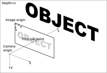
The Image Coordinate System describes the position of points in the image space, and the Camera Coordinate System describes the corresponding point in 3D space. The intrinsics of the camera are used to transform a point between the two coordinate systems.
The Image Coordinate System originates at the top-left of the image. The u- and v-axes, in pixel units, are aligned with the way pixels are stored in memory.
The Camera Coordinate System has its origin at the optical center of the camera. The x-axis points to the right of the image plane and the y-axis points to the bottom of the image plane. The z-axis points forward, along the optical axis. The x- and y-axes point in the same direction as the image u- and v-axes, respectively. The camera coordinate axes are in metric units.
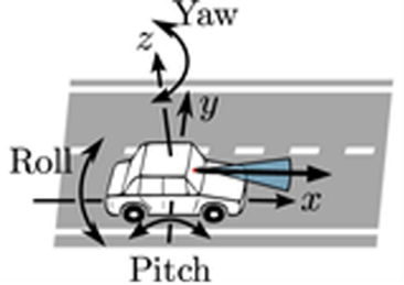
Radar Coordinate System
The Radar Coordinate System is centered at the radar's geometric center and the system axis follow the AUTOSAR and ISO-8855 standard. The x-axis points forward, to the front of the car. The y-axis points to the left of the car and the z-axis points up.
LIDAR Coordinate System
The LIDAR manufacturer defines the LIDAR Coordinate System.
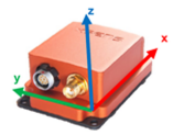
IMU Coordinate System
In the IMU Coordinate System, the x-axis points forward, to the front of the car. The y-axis points to the left of the car, and the z-axis points up. The origin is located inside the case of the sensor at the accelerometer.
GPS Coordinate System
Please refer to World Coordinate System.
Rig Coordinate System
The Rig Coordinate System serves two purposes:
- It is the base coordinate systems all sensor extrinsics are related to.
- It provides a coordinate system to describe the environment relative to the ego-vehicle.
The origin of this coordinate system is the projection of the center of the rear axle onto the nominal ground. X direction points to the motion direction of the vehicle, Y axis points to the left side of the vehicle and Z axis points up to the sky.
The Rig Coordinate System is the one that dwRig relies on to describe all sensor positions.
Local Coordinate System
The Local Coordinate System represents an arbitrary Cartesian coordinate system that describes the space and environment around our vehicle. One can assume this is a square centered in the ego vehicle and it is not a permanently fixed coordinate system in respect to the world. Often at a given instant of time, this coordinate system aligns with the Rig Coordinate System in origin and axis.
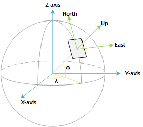
World Coordinate System
The World Coordinate System represents positions in map/earth coordinates and is expressed in World Geodetic System 1984 (WGS84) and ENU axis convention.
The origin is defined at an arbitrary point on the Earth surface. x, y and z axes defined the tangent plane at that origin point, such that (x,y,z) corresponds to (east, north, up).
The NVIDIA® DriveWorks maps module provides helper functions to transform into local Cartesian coordinates.
Custom Coordinate System
The Custom Coordinate System represents any arbitrary coordinate system that the developer wants to use. It is the developer's responsibility to keep other users informed of the relations between this coordinate system and any of the DriveWorks-defined coordinate systems.