Table of Contents
- Note
- SW Release Applicability: This tutorial is applicable to modules in both NVIDIA DriveWorks and NVIDIA DRIVE Software releases.
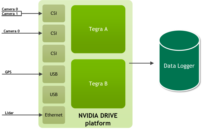
This section provides guidance on recording a limited number of sensors on a single NVIDIA® Xavier® processor.
Basic Steps
The following are the steps to log data in the device.
- Step 1: Verify the Sensors Are Collecting Data
- Step 2: Configure the Device to Acquire Data
- Step 3: Start the Recording Application and Acquire the Data
Prerequisites
Before you can use the NVIDIA® DriveWorks recording tools or DriveWorks sample sensor applications, you must ensure that:
- NVIDIA DRIVE platform is flashed with an operating system.
- DriveWorks SDK is installed on the device. For more information, see Getting Started.
- Only supported sensors are used.
- An ext4-formmated eSATA/USB3.0 SSD is mounted on the target
Step 1: Verify the Sensors Are Collecting Data
In this step, you will connect the sensor to the device and then verify that the sensor is collecting data.
- Warning
- Turn off the device before connecting or disconnecting a sensor.
You can determine whether the sensor is correctly connected and collecting data by starting the appropriate sample application. The following table lists some of the samples.
| Sensor | Sample Application |
|---|---|
| Camera | sample_camera_gmsl sample_camera_multiple_gmsl |
| GPS | sample_gps_logger |
| Lidar | sample_lidar_replay |
| Radar | sample_radar_replay |
| IMU | sample_imu_logger |
| CAN | sample_canbus_logger |
For a complete list of samples, see Samples.
Step 2: Configure the Device to Acquire Data
After verifying that the sensors are functional, you can create a DriveWorks Rig Configuration file to specify sensors for recording. For more information on creating a rig file for recording, see the recording Configuration Reference or the Examples section in this chapter.
Step 3: Start the Recording Application and Acquire the Data
After you modify the configuration file to collect and store the data, you can begin logging the data from the sensors. You can use the basic, TextUI, or GUI tool:
- tools/capture/recorder
- tools/capture/recorder-tui
- tools/capture/recorder-qtgui
All tools collect the data from the sensors, synchronize the data by adding time stamps, and save the data to the storage device.
Recording SocketCAN Data
If you are using the Basic Recording Tool, and recording data from SocketCAN on Linux, you must start the recording tool with root privileges. For example:
# sudo tools/capture/recorder
The sensor driver uses an IOCTL command to enable HW timestamping for the TegraCAN interface.
The sudo preface is not required for the TextUI Recording Tool or the GUI Recording Tool, as it is handled internally.
Examples
This section shows how to log data from the connected sensors. The applications can check that the sensors can collect data and saves the data to the Xavier System on Chip (SOC).
Cameras
This section explains how to use the DriveWorks recorder to acquire data from one or more cameras.
Recording from a Single Camera
This procedure shows how to record data from a single (AR0231) camera.
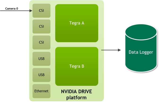
To record data from a single camera
- With the device powered off, connect the camera to port A0 of a camera group.
- Warning
- Turn off the device before connecting or disconnecting a sensor.
- Turn on the device and open a terminal window.
- On the target, navigate to:
/usr/local/driveworks/bin/
Run the following command to verify that your camera is correctly connected to the device:
If the camera type is c-ov10649-b1 and the CSI port is the default ab, execute:
./sample_camera_gmsl
Otherwise, execute:
./sample_camera_gmsl --camera-type=<camera_type>
Where <camera_type> is the camera.
For example, if your camera is an AR0231-RCCB sensor with a SF3324 module and you want to run in BAE exposure mode, run the following command:
./sample_camera_gmsl --camera-type=ar0231-rccb-bae-sf3324
A window appears with video if the camera is correctly connected to the device and the drivers are running.
Close the window to stop the camera application.
- On the target, navigate to:
/usr/local/driveworks/tools/capture/
- Copy the default configuration file in
configs/hyperion7_1/release.json, and include the following sensor block for camera. All the other sensor blocks can be removed.{"name": "camera:front:center:120fov","nominalSensor2Rig": {"quaternion": [-0.502444,0.507493,-0.497444,0.492494],"t": [1.749,-0.1,1.47]},"parameter": "camera-type=ar0231-rccb-bae-sf3324,camera-group=a,camera-count=1,format=h264,output-format=yuv","properties": {"Model": "ftheta","bw-poly": "0.0 0.000545421498827636 -1.6216719633103e-10 -4.64720492990289e-12 2.85224527762934e-16","cx": "960","cy": "604","height": "1208","width": "1920"},"protocol": "camera.gmsl","sensor2Rig": {"quaternion": [-0.502444,0.507493,-0.497444,0.492494],"t": [1.749,-0.1,1.47]}} - Save the modified configuration file.
Run the following command to log the data from the camera:
# ./recorder-tui <modified_file.json>
A TextUI interface appears on the console as below:
Recorder @ release: Ready to start
    4.672 GB    135.591 MB/s camera:front:center:120fov
    4.672 GB    135.591 MB/s TOTAL
Last output: [19-8-2018 0:48:58] SensorManager: started
Press s<Enter> to start/stop. Press q<Enter> to quit.
Enter
sto start recording data from the camera.After a few seconds, enter
sto stop recording data.- Warning
- Stop recording data and then quite the application. If you quit the app before you stop recording data, you will corrupt the acquired data.
The sensor data will be available on the ext4-formmated eSATA/USB SSD.
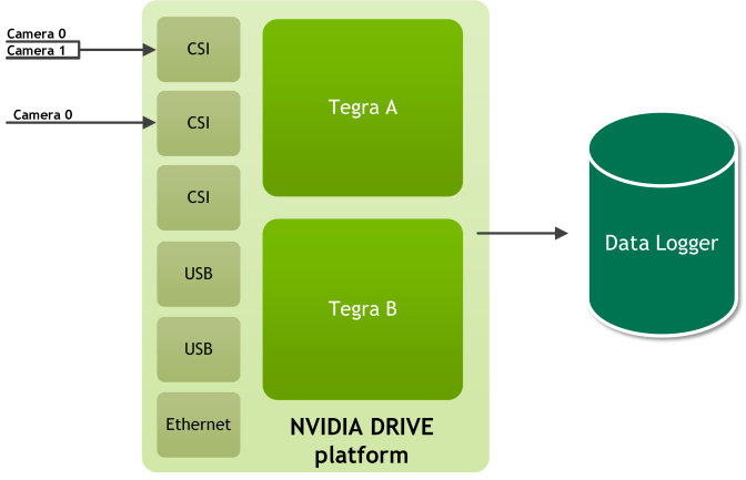
Recording from Three Cameras
This procedure demonstrates how to record data from three AR0231 camera. The cameras connected to the following ports:
| Camera Group | Port Name | Camera Type | Ports |
|---|---|---|---|
| A | a | ar0231-rccb-bae-sf3324 | Port 0 Port 1 |
| B | c | ar0231-rccb-bae-sf3324 | Port 0 |
- Warning
- Turn off the device before connecting or disconnecting a sensor.
To acquire data from three cameras
- Turn on the device and open a terminal window.
- On the target, navigate to:
/usr/local/driveworks/bin/
- Run sample_camera_multiple_gmsl to verify that your camera is correctly connected to the device. The following command is for cameras connected at 0 and 1 on port-a and 0 on port-c:
./sample_camera_multiple_gmsl --type-a=ar0231-rccb-bae-sf3324 --type-c=ar0231-rccb-bae-sf3324 \
--selector-mask=00110001
- Warning
- Cameras must be connected to the port in ascending order (0, 1, 2, 3).
- On the target, navigate to:
/usr/local/driveworks/tools/capture/
- Copy the default configuration file in
configs/hyperion7_1/release.json, and include the following sensor block for camera. All the other sensor blocks can be removed.{"name": "camera:front:center:120fov","nominalSensor2Rig": {"quaternion": [-0.502444,0.507493,-0.497444,0.492494],"t": [1.749,-0.1,1.47]},"parameter": "camera-type=ar0231-rccb-bae-sf3324,camera-group=a,camera-count=2,siblingIndex=0,format=h264,output-format=yuv","properties": {"Model": "ftheta","bw-poly": "0.0 0.000545421498827636 -1.6216719633103e-10 -4.64720492990289e-12 2.85224527762934e-16","cx": "960","cy": "604","height": "1208","width": "1920"},"protocol": "camera.gmsl","sensor2Rig": {"quaternion": [-0.502444,0.507493,-0.497444,0.492494],"t": [1.749,-0.1,1.47]}},{"name": "camera:front:right:120fov","nominalSensor2Rig": {"quaternion": [-0.502444,0.507493,-0.497444,0.492494],"t": [1.749,-0.1,1.47]},"parameter": "camera-type=ar0231-rccb-bae-sf3324,camera-group=a,camera-count=2,siblingIndex=1,format=h264,output-format=yuv","properties": {"Model": "ftheta","bw-poly": "0.0 0.000545421498827636 -1.6216719633103e-10 -4.64720492990289e-12 2.85224527762934e-16","cx": "960","cy": "604","height": "1208","width": "1920"},"protocol": "camera.gmsl","sensor2Rig": {"quaternion": [-0.502444,0.507493,-0.497444,0.492494],"t": [1.749,-0.1,1.47]}},{"name": "camera:rear:center:120fov","nominalSensor2Rig": {"quaternion": [-0.502444,0.507493,-0.497444,0.492494],"t": [1.749,-0.1,1.47]},"parameter": "camera-type=ar0231-rccb-bae-sf3324,camera-group=c,camera-count=1,format=h264,output-format=yuv","properties": {"Model": "ftheta","bw-poly": "0.0 0.000545421498827636 -1.6216719633103e-10 -4.64720492990289e-12 2.85224527762934e-16","cx": "960","cy": "604","height": "1208","width": "1920"},"protocol": "camera.gmsl","sensor2Rig": {"quaternion": [-0.502444,0.507493,-0.497444,0.492494],"t": [1.749,-0.1,1.47]}} - Save the modified configuration file.
Run the following command to log the data from the camera:
# ./recorder-tui <modified_file.json>
A TextUI interface appears on the console as below:
Recorder @ release: Ready to start
    4.672 GB    1.591 MB/s camera:front:center:120fov
    4.700 GB    1.585 MB/s camera:front:right:120fov
    4.987 GB    2.035 MB/s camera:rear:center:120fov
    14.359 GB   5.211 MB/s TOTAL
Last output: [19-8-2018 0:48:58] SensorManager: started
Press s<Enter> to start/stop. Press q<Enter> to quit.
After a few seconds, enter
sto stop recording data.- Warning
- Stop recording data and then quite the application. If you quit the app before you stop recording data, you will corrupt the acquired data.
The sensor data will be available on the ext4-formmated eSATA/USB SSD.
GPS
This section shows how to acquire data from a GPS sensor.
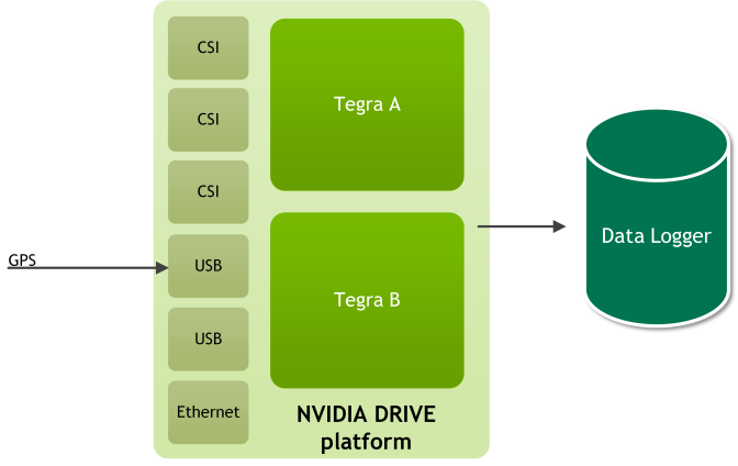
To determine GPS settings for the rig file
- With the device powered off, connect the GPS sensor to the device per vendor documentation. For example, Garmin connection instructions are on page 8 at:
http://static.garmin.com/pumac/GPS_18x_Tech_Specs.pdf - Determine on which serial port the device is enumerated:
dmesg | grep ttyUSB
- Determine the baud rate at which the GPS device transmits data. This information can be obtained from vendor documentation. For example, Garmin LVC GPS 18x uses 4800 baud.
- Set the baud rate to the serial port. For example:
stty -F /dev/ttyUSB0 4800
- Verify that GPS data is being received:
cat /dev/ttyUSB0 4800
- Update the GPS settings in the rig file with the serial port and baud rate.
To acquire data from a GPS sensor
- With the device powered off, connect the GPS sensor to the device.
- Warning
- Turn off the device before connecting or disconnecting a sensor.
- Turn on the device and open a terminal window.
- On the target, navigate to:
/driveworks/bin/
- Run the following command to verify that your GPS sensor is correctly connected to the device:
./sample_gps_logger --driver=gps.uart --params=device=/dev/ttyUSB0,baud=4800
Console prints will display the data acquired if the GPS sensor is correctly connected to the device and the drivers are running. - On the target, navigate to:
/usr/local/driveworks/tools/capture/
- Copy the default configuration file in
configs/hyperion7_1/release.json, and include the following sensor block for gps. All the other sensor blocks can be removed.{"name": "gps:garmin","nominalSensor2Rig": {"quaternion": [-0.502444,0.507493,-0.497444,0.492494],"t": [1.749,-0.1,1.47]},"parameter": "device=/dev/ttyUSB0,baud=115200","protocol": "gps.uart","sensor2Rig": {"quaternion": [-0.502444,0.507493,-0.497444,0.492494],"t": [1.749,-0.1,1.47]}} Run the following command to log the data from the camera:
# ./recorder-tui <modified_file.json>
A TextUI interface appears on the console as below:
Recorder @ release: Ready to start
    1.057 MB    25.591 KB/s gps:garmin
    1.057 MB    25.591 KB/s TOTAL
Last output: [19-8-2018 0:48:58] SensorManager: started
Press s<Enter> to start/stop. Press q<Enter> to quit.
After a few seconds, enter
sto stop recording data.- Warning
- Stop recording data and then quite the application. If you quit the app before you stop recording data, you will corrupt the acquired data.
The sensor data will be available on the ext4-formmated eSATA/USB SSD.
Lidar
This section shows how to acquire data from a Lidar sensor.
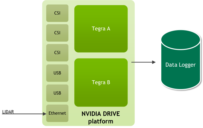
Determining the Lidar IP Address and Port
To determine the IP address and port for a Quanergy LIDAR
- Connect the Lidar Ethernet port to eth0 port of Xavier A.
- Connect the Quanergy to a router switch and connect this router to Xavier A eth0. The IP of router will be in range 192.168.x.x.
- Find the IP address by running:
# nmap -sn 192.168.1.0/25
If Quanergy is detected, you will see an IP address associated with Quanergy system. - To obtain the port number, consult the Quanergy technical specification. The following is an example of rig sensor block for a Quanergy LIDAR. {"name": "lidar:quanergy","nominalSensor2Rig": {"quaternion": [-0.502444,0.507493,-0.497444,0.492494],"t": [1.749,-0.1,1.47]},"parameter": "device=QUAN_M81A,ip=192.168.1.8,port=4141,scan-frequency=10","protocol": "lidar.socket","sensor2Rig": {"quaternion": [-0.502444,0.507493,-0.497444,0.492494],"t": [1.749,-0.1,1.47]}}
To determine the IP address for a Velodyne LIDAR
- Connect the LIDAR to the eth0 port of Xavier A.
- Obtain the default IP address and port number from the Velodyne technical specification.
- Set up the IP of eth0 with:
# ifconfig eth0 <lidar_address>
By default, the Lidar IP address is 192.168.1.201. Ensure this IP does not conflict with the AURIX, Xavier A, or Xavier B IPs. The following is an example of recorder-config.json with a Velodyne 32 LIDAR.The value for params above is:{"name": "lidar:velodyne","nominalSensor2Rig": {"quaternion": [-0.502444,0.507493,-0.497444,0.492494],"t": [1.749,-0.1,1.47]},"parameter": "device=VELO_HDL32E,ip=192.168.1.201,port=2368,scan-frequency=10","protocol": "lidar.socket","sensor2Rig": {"quaternion": [-0.502444,0.507493,-0.497444,0.492494],"t": [1.749,-0.1,1.47]}}"device=VELO_HDL32E,ip=192.168.1.201,port=2368,scan-frequency=10"
For Velodyne 16, the device name is VELO_VLP16. For Velodyne 64, the device is VELO_HDL64E.
Recording Data from a Lidar Sensor
After you obtain the Lidar IP address and port, you can obtain Lidar data.
To acquire data from a Lidar sensor
- With the device powered off, connect the LIDAR sensor to the device.
- Warning
- Turn off the device before connecting or disconnecting a sensor.
- Turn on the device and open a terminal window.
- On the target, navigate to:
/driveworks/bin/
- Run the following command to verify that your LIDAR sensor is correctly connected to the device. For example:
./sample_lidar_replay --device=VELO_HDL32E --ip=192.168.1.201 --port=2368 \
--scan-frequency=10
A window appears that displays a point cloud if the LIDAR sensor is correctly connected to the device and the drivers are running. Close the window to stop the lidar replay application. - Go to the following location in the DriveWorks folder:
/usr/local/driveworks/tools/capture/
- Copy the default configuration file in
configs/hyperion7_1/release.json, and include the following sensor block for lidar:Where:{"name": "lidar:side","nominalSensor2Rig": {"quaternion": [-0.502444,0.507493,-0.497444,0.492494],"t": [1.749,-0.1,1.47]},"parameter": "ip=<ip_address>,port=<port>,device=<device_name>,frequency=10","protocol": "lidar.socket","sensor2Rig": {"quaternion": [-0.502444,0.507493,-0.497444,0.492494],"t": [1.749,-0.1,1.47]}}<ip_address>is the IP address of the LIDAR sensor.<port>is the port for the Lidar sensor.
Run the following command to log the data from the camera:
# ./recorder-tui <modified_file.json>
A TextUI interface appears on the console as below:
Recorder @ release: Ready to start
    50.057 MB    400.591 KB/s lidar:side
    50.057 MB    400.591 KB/s TOTAL
Last output: [19-8-2018 0:48:58] SensorManager: started
Press s<Enter> to start/stop. Press q<Enter> to quit.
After a few seconds, enter
sto stop recording data.- Warning
- Stop recording data and then quite the application. If you quit the app before you stop recording data, you will corrupt the acquired data.
The sensor data will be available on the ext4-formmated eSATA/USB SSD.
Multiple Sensor Types
This section shows you how to acquire data from multiple sensors connected to the device. This section assumes that you know how to verify that each sensor is working and that you have a rig configuration file.
To acquire data from multiple cameras, an HDL-32 LIDAR, and a GPS Sensors
This procedure shows you how to log the data from the following sensors:
- Three AR0231 cameras
- One HDL-32 LIDAR sensor
- One GPS Sensor
The cameras are connected to the following ports:
| Camera Group | Port Name | Camera Type | Ports |
|---|---|---|---|
| A | a | ar0231-rccb-bae-sf3324 | Port 0 Port 1 |
| B | c | ar0231-rccb-bae-sf3324 | Port 0 |
- Warning
- Turn off the device before connecting or disconnecting a sensor.
Change the following sections in the configuration file to log the data from the sensors:
{"name": "camera:front:center:120fov","nominalSensor2Rig": {"quaternion": [-0.502444,0.507493,-0.497444,0.492494],"t": [1.749,-0.1,1.47]},"parameter": "camera-type=ar0231-rccb-bae-sf3324,camera-group=a,camera-count=2,siblingIndex=0,format=h264,output-format=yuv","properties": {"Model": "ftheta","bw-poly": "0.0 0.000545421498827636 -1.6216719633103e-10 -4.64720492990289e-12 2.85224527762934e-16","cx": "960","cy": "604","height": "1208","width": "1920"},"protocol": "camera.gmsl","sensor2Rig": {"quaternion": [-0.502444,0.507493,-0.497444,0.492494],"t": [1.749,-0.1,1.47]}},{"name": "camera:front:right:120fov","nominalSensor2Rig": {"quaternion": [-0.502444,0.507493,-0.497444,0.492494],"t": [1.749,-0.1,1.47]},"parameter": "camera-type=ar0231-rccb-bae-sf3324,camera-group=a,camera-count=2,siblingIndex=1,format=h264,output-format=yuv","properties": {"Model": "ftheta","bw-poly": "0.0 0.000545421498827636 -1.6216719633103e-10 -4.64720492990289e-12 2.85224527762934e-16","cx": "960","cy": "604","height": "1208","width": "1920"},"protocol": "camera.gmsl","sensor2Rig": {"quaternion": [-0.502444,0.507493,-0.497444,0.492494],"t": [1.749,-0.1,1.47]}},{"name": "camera:rear:center:120fov","nominalSensor2Rig": {"quaternion": [-0.502444,0.507493,-0.497444,0.492494],"t": [1.749,-0.1,1.47]},"parameter": "camera-type=ar0231-rccb-bae-sf3324,camera-group=c,camera-count=1,format=h264,output-format=yuv","properties": {"Model": "ftheta","bw-poly": "0.0 0.000545421498827636 -1.6216719633103e-10 -4.64720492990289e-12 2.85224527762934e-16","cx": "960","cy": "604","height": "1208","width": "1920"},"protocol": "camera.gmsl","sensor2Rig": {"quaternion": [-0.502444,0.507493,-0.497444,0.492494],"t": [1.749,-0.1,1.47]}},{"name": "gps:garmin","nominalSensor2Rig": {"quaternion": [-0.502444,0.507493,-0.497444,0.492494],"t": [1.749,-0.1,1.47]},"parameter": "device=/dev/ttyUSB0,baud=115200","protocol": "gps.uart","sensor2Rig": {"quaternion": [-0.502444,0.507493,-0.497444,0.492494],"t": [1.749,-0.1,1.47]}},{"name": "lidar:side","nominalSensor2Rig": {"quaternion": [-0.502444,0.507493,-0.497444,0.492494],"t": [1.749,-0.1,1.47]},"parameter": "ip=<ip_address>,port=<port>,device=<device_name>,frequency=10","protocol": "lidar.socket","sensor2Rig": {"quaternion": [-0.502444,0.507493,-0.497444,0.492494],"t": [1.749,-0.1,1.47]}}Where:
<ip_address>is the IP address of the LIDAR sensor.<port>is the port for the LIDAR sensor.
Save the modified configuration file.
Run the following command to log the data from the sensors:
# ./recorder-tui <modified_file.json>
A TextUI interface appears on the console as below:
Recorder @ release: Ready to start
    4.672 GB     1.591 MB/s   camera:front:center:120fov
    4.700 GB     1.585 MB/s   camera:front:right:120fov
    4.987 GB     2.035 MB/s   camera:rear:center:120fov
    1.057 MB     25.591 KB/s  gps:garmin
    50.057 MB    400.591 KB/s lidar:front
    14.410 MB    6.137 MB/s TOTAL
Last output: [19-8-2018 0:48:58] SensorManager: started
Press s<Enter> to start/stop. Press q<Enter> to quit.
After a few seconds, enter
sto stop recording data.- Warning
- Stop recording data and then quite the application. If you quit the app before you stop recording data, you will corrupt the acquired data.
The sensor data will be available on the ext4-formmated eSATA/USB SSD.
Sensor Data Quality
To sanity-check the Lidar and Camera data
- Use the recorder tool to capture Lidar and camera data on someone walking past.
- Use the replayer tool on the captured data to verify that:
- Data from the different sensors are roughly in sync and
- Lidar data makes sense (i.e. the shape of the person walking past).
To sanity-check the Lidar data
- For Lidar, compare the Lidar plot coming from the PDK with the reference plots obtained from any other Linux x86 machine, at the same location.
To sanity-check GPS data
- If you are testing in a Lab, ensure the GPS produces the same coordinates over time. It should be roughly the same because it is not moving.
To determine if a sensor is broken
- Feed each offline file to the corresponding DriveWork sensor sample. If one of the files fails, you know there is a problem with the sensor.
- Read the documentation provided by the sensor manufacturer.