Setting Up the Cameras
The platform provides multiple video and camera ports.
Before using these cameras with the NvMedia sample applications, the cameras must be attached to the ports in a specific order. If you fail to do so, NvMedia reports errors.
Warning: | Before connecting/disconnecting cameras to/from the platform, disconnect the power. Failure to do so may damage the camera. |
For information on setting up the board, see
Setting Up Your Platform.
Camera Interfaces
The platform provides GMSL camera interfaces. The GMSL camera interfaces:
• Provide 16 simultaneous GMSL camera inputs
• Route camera data to either Tegra SoC
• Control any camera from either Tegra
• SoC generates a PWM signal on a GPIO pin that is connected to all deserializers. This common PWM signal is then forwarded to all 16 GMSL cameras to achieve frame synchronization.
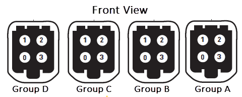
For information on the connectors, see the front view board image in
Setting Up Your Platform.
Mapping Connectors
Each GMSL camera group can be routed to the chip using a GMSL deserializer.
• GMSL cameras are organized into quads. For example, A, B, C and D as available.
• All four cameras within a quad must be identical.
• Different cameras may be used in different quads.
• When connecting or disconnecting the GMSL cameras, ensure the power is off. If the power is ON the GMSL camera or the platform may be damaged.
The camera mapping for the E3550 board are as follows:
Homogeneous Camera Types
Homogeneous camera types are required per camera group.
• All cameras within a particular camera group must be of the same type.
• Each group can have a different type of camera.
For example, the cameras attached to group A must all be of the same camera type, they cannot be mixed.
Connecting the Cameras
When connecting the cameras to a specific group, attach the cameras in sequential order. For example, within Group A:
• Attach the first camera to A0.
• If used, attach the next camera to A1.
• If used, attach the next camera to A2.
• If used, attach the next camera to A3.
Failure to attach cameras in this order results in NvMedia generating error messages.
To connect the cameras
1. Using the camera coax cable, connect the camera to the platform at Port A0.
Warning: | • The GMSL camera must be 8V tolerant. Refer to the platform datasheet for details on the electrical requirements for the GMSL camera. • Always turn off main power before connecting or disconnecting cameras. |
2. Connect subsequent camera to the next port in the group.
To connect the camera using the Fakra cable
1. Using the camera Fakra coax cable, connect the camera to the platform at Port A0.
2. Connect any subsequent cameras to the next port in the group.
To connect multiple cameras using the quad camera breakout cable
1. Connect the quad camera breakout cable to the platform camera group A.
2. Using the Fakra coax cable, connect the GMSL camera to the other end of the quad camera breakout cable.
3. Connect any subsequent cameras to each connector of the quad camera breakout cable.
4. The mapping of the quad camera breakout cable:
• Green: A0
• Red: A1
• Blue: A2
• White: A3
To run the sample applications
• Use the --aggregate <n> option to specify the number of cameras connected.
Where <n> maps as follows:
• n=1 maps to link0
• n=2 maps to link0 and link1 etc.
• n=4 maps to all links
Camera Power Control
The NvMedia camera applications use an Ethernet-based Control Communication protocol to request camera power on/off at the AURIX processors. It is not necessary to manually turn the camera power on/off through the AURIX shell interface.
To enable camera applications to use Ethernet-based control communication
For example, Sekonix AR0231 camera connected to A0 port, and an HDMI monitor connected to the HDMI port.
2. Launch a terminal window and navigate to the following directory.
On Ubuntu rootfs:
/home/nvidia/drive-t186ref-linux/samples/nvmedia/ipp_raw/<x11/wayland/egldevice>
On Genivi rootfs:
/home/root/samples/nvmedia/ipp_raw/<wayland/egldevice>
3. Enter the command.
./nvmipp_raw -cf ../ddpx-a.conf -c SF3324-CSI-A -d 0
Where:
• ddpx-a.conf specifies the configuration file that specifies all the parameters for your configuration.
• SF3324-CSI-A specifies the capture-name parameter as defined in the configuration file for the SF3324 camera connected to connector A0.
• -d 0 specifies the display number.
4. To obtain the available display devices for Tegra, execute the command:
./nvmipp_raw -h
The available display devices are identified.
5. Select the desired display ID.