CAN Driver
Linux releases support two instances of NVIDIA Tegra Controller Area Network (TegraCAN). The CAN controller for Tegra family devices is the Bosch MTTCAN controller IP.
TegraCAN provides two SocketCAN interfaces in the Linux kernel. The SocketCAN interface is similar to network interfaces in Linux kernel. SocketCAN documentation is available in Linux kernel documentation online at:
<top>/<kernel_sources>/documentation/networking/can.txt
For information about SocketCAN limitations, see the Release Notes.
There are two implementations of MTTCAN SocketCAN driver:
• mttcan driver that controls CAN controller directly through CPU running Linux
• mttcan-ivc that uses CAN driver services through IVC and implemented in SPE-FW. This driver can potentially be used by both SPE firmware and Linux.
The selection of either mttcan or mttcan-ivc is done through device tree solution. Ensure that both drivers for a given CAN controller are not simultaneously enabled through device tree.
Enabling CAN Driver in Linux Kernel
You must enable the CAN driver using the following procedures.
To enable SPE based mttcan_ivc driver
1. For the targeted board device tree include file, make the following device tree changes. The supported board files include tegra186-vcm31-p2379-common.dtsi, tegra186-vcm31-p2382-common.dtsi, or tegra186-vcm31-p3407-common.dtsi. For custom board configurations, make the following changes.
1. Enable mttcan0-ivc and mttcan1-ivc in the target device tree:
mttcan0-ivc {
status = "okay";
};
mttcan1-ivc {
status = "okay";
};
2. Disable mttcan driver in the target device tree:
mttcan@c310000 {
…
status = "disabled";
;
mttcan@c320000 {
…
status = "disabled";
};
2. Make sure that SPE-FW is loaded by enabling the -L flash option. Ensure that your global_storage.cfg has SPE and Warmboot binaries enabled.
MTTCAN as a Module
Before running MTTCAN as a module, the user must ensure it is loaded on the target.
To install modules
1. On the target, determine whether following modules are loaded, by running the lsmod command in the Linux shell.
• can.ko
• can-dev.ko
• mttcan.ko
• mttcan_ivc.ko
2. If the modules are not loaded, determine whether they are in following, directory:
/lib/modules
3. If the modules are not in this directory, set the following CONFIG options in defconfig and rebuild kernel.
CONFIG_CAN=m
CONFIG_CAN_RAW=m
CONFIG_CAN_DEV=m
CONFIG_MTTCAN=m
CONFIG_MTTCAN_IVC=m
4. Alternatively, these options can be set using the instructions described in Compiling the Kernel in the NVIDIA DRIVE OS 5.1 Linux PDK Development Guide, “To compile the kernel” topic, steps 1-3 to:
• Setup the environment macros
• Set the kernel source directory
• Create an output directory and configure the kernel for the board
5. Execute the following command.
make -C kernel O=${PWD}/out-t186ref-linux DEFCONFIG_PATH=$PWD/t19x/arch/arm64/configs menuconfig
[*] Networking support --->
<M> CAN bus subsystem support --->
<M> Raw CAN Protocol (raw access with CAN-ID filtering)
<M> CAN Device Drivers --->
<M> Platform CAN drivers with Netlink support
<M> Bosch M_TTCAN Devices
<M> Bosch M_TTCAN IVC Devices
6. Exit and save.
7. Rebuild the kernel and copy the kernel Image from the kernel out directory to:
drive-t186ref-linux/kernel
For more information, see Compiling the Kernel in the NVIDIA DRIVE OS 5.1 Linux PDK Development Guide.
8. Reflash the target.
For more information, see Flashing the Board in the Foundation Development Guide.
9. Load all required modules.
# modprobe mttcan
# modprobe mttcan_ivc
This command assumes module dependencies are properly set.
10. If the modprobe command fails, manually load the modules:
insmod /lib/modules/<KERNEL_VERSION>/kernel/net/can/can.ko
insmod /lib/modules/<KERNEL_VERSION>/kernel/drivers/net/can/can-dev.ko
insmod /lib/modules/<KERNEL_VERSION>/t18x/drivers/staging/mttcan/mttcan.ko
insmod /lib/modules/<KERNEL_VERSION>/t18x/drivers/net/can/mttcan /ivc/mttcan_ivc.ko
Note: | The <KERNEL_VERSION> is in the form of x.x.xx-rtxx-tegra. For example, 4.4.38-rt49-tegra. |
MTTCAN as a Kernel Built-in Driver
When you build the MTTCAN driver along with the kernel, it is part of the kernel binary.
2. Set the following CONFIG options in defconfig.
For more information, see Compiling the Kernel in the NVIDIA DRIVE OS 5.1 Linux PDK Development Guide.
CONFIG_CAN=y
CONFIG_CAN_RAW=y
CONFIG_CAN_DEV=y
CONFIG_MTTCAN=y
CONFIG_MTTCAN_IVC=n
Note: | Only one of the two configurations can be enabled CONFIG_MTTCAN or CONFIG_MTTCAN_IVC. Both cannot be statically linked simultaneously. |
3. Alternatively, these options can be set using the instructions described in Compiling the Kernel in the NVIDIA DRIVE OS 5.1 Linux PDK Development Guide, “To compile the kernel” topic, steps 1-3 to:
• Setup the environment macros
• Set the kernel source directory
• Create an output directory and configure the kernel for the board
4. Execute the following command.
make -C kernel O=${PWD}/out-t186ref-linux DEFCONFIG_PATH=$PWD/t19x/arch/arm64/configs menuconfig
[*] Networking support --->
<M> CAN bus subsystem support --->
<M> Raw CAN Protocol (raw access with CAN-ID filtering)
<M> CAN Device Drivers --->
<M> Platform CAN drivers with Netlink support
<M> Bosch M_TTCAN Devices
5. Exit and save.
6. Build the kernel and copy the modules from the kernel Image and zImage as follows:
cp ${PWD}/out-t186ref-linux/arch/arm64/boot/zImage <top>/drive-t186ref-linux/kernel
cp ${PWD}/out-t186ref-linux/arch/arm64/boot/Image <top>/drive-t186ref-linux/kernel
For more information, see Compiling the Kernel in the NVIDIA DRIVE OS 5.1 Linux PDK Development Guide.
7. Reflash the target system.
For more information, see Flashing the Board in the Foundation Development Guide.
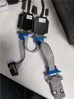
Setting Up CAN Loopback
On E3550, you need a special loopback cable with termination to test CAN. Consult the CAN_Loopback Cable Build Instructions to make the CAN cable. It identifies the components required and provides instructions for building the cable.
There are six (6) CAN controller pins coming out of harness. The CAN2 and CAN6 controller can be accessed from the SoC. The CAN2 controller is detected as can0 and the CAN6 controller is detected as can1. can0 and can1 are software given names by Linux.
Use the CAN loopback cable to connect the two CAN controllers of the SoC. Connect CAN1_2 dsub and CAN_6_4 dsub using the loopback cable as follows:
Setting up SocketCAN Interface
After ensuring mttcan module is loaded or the driver is enabled, use following commands to set up the CAN0 network interface. To enable the CAN1 interface, replace can0 with can1.
Setting Up the CAN0 Interface
To set can0 interface bitrate
• Enter:
#ip link set can0 type can bitrate 500000
In this command, bitrate can be any valid CAN bitrate for stand CAN.
Note: | 125000(125 Kbps), 250000(250 Kbps), 500000(500 Kbps) and 1000000(1Mbps) are supported bitrates for Tegra MTTCAN driver. Any other bitrate is not validated on Tegra MTTCAN driver. Only 500000 (500 Kbps) bitrate is supported for Tegra MTTCAN-IVC. Other bitrates are not enabled on Tegra MTTCAN-IVC driver out of box. Details are available in the SPE documentation. |
To get the supported commands
There are various parameters that can be set for CAN interface.
• Enter:
# ip link set can0 type can help
This command prints the following help:
Usage: ip link set DEVICE type can
[ bitrate BITRATE [ sample-point SAMPLE-POINT] ] |
[ tq TQ prop-seg PROP_SEG phase-seg1 PHASE-SEG1
phase-seg2 PHASE-SEG2 [ sjw SJW ] ]
[ dbitrate BITRATE [ dsample-point SAMPLE-POINT] ] |
[ dtq TQ dprop-seg PROP_SEG dphase-seg1 PHASE-SEG1
dphase-seg2 PHASE-SEG2 [ dsjw SJW ] ]
[ loopback { on | off } ]
[ listen-only { on | off } ]
[ triple-sampling { on | off } ]
[ one-shot { on | off } ]
[ berr-reporting { on | off } ]
[ fd { on | off } ]
[ restart-ms TIME-MS ]
[ restart ]
Where: BITRATE := { 1..1000000 }
SAMPLE-POINT := { 0.000..0.999 }
TQ := { NUMBER }
PROP-SEG := { 1..8 }
PHASE-SEG1 := { 1..8 }
PHASE-SEG2 := { 1..8 }
SJW := { 1..4 }
RESTART-MS := { 0 | NUMBER }
To bring up the can0 interface
• Enter:
#ip link set up can0
Enabling the Flexible Data Rate Mode on MTTCAN
SocketCAN currently supports classic (or standard) CAN mode and Flexible Data (FD) rate. If the devices on your CAN network support FD, the user can enable FD rate mode on MTTCAN.
To enable FD mode
1. If the interface is already up, disable it.
#ip link set down can0
2. Set the flexible data rate for the dbitrate option to any valid data rate, provided that dbitrate is greater than the specified bitrate value.
#ip link set can0 type can bitrate 500000 dbitrate 2000000 berr-reporting on fd on
Note: | For dbitrate support, iproute package version 2.4.0.0 or later is required. Additionally, the maximum dbitrate support depends on PHY chip on platform. Consult the PHY datasheet to identify and obtain the maximum allowed data bitrate. dbitrate 1000000 (1 Mbps) and 2000000 (2 Mbps) are supported data bitrates. Any other dbitrate is not validated on TegraMTTCAN driver. |
To check detail statics of the link
• Enter:
#ip -details -statistics link show can0
Miscellaneous Information About OSS SocketCAN Tools
You can use the open source can-utils package to get information about SocketCAN.
#apt-get install can-utils
How to Test CAN
The following section describes how to test CAN.
Test Classic (Non-FD) CAN
1. First, configure both the CAN interfaces with required bitrates:
# sudo ip link set can0 type can bitrate 500000 berr-reporting on
# sudo ip link set can0 up
# sudo ip link set can1 type can bitrate 500000 berr-reporting on
# sudo ip link set can1 up
2. Open a new ssh terminal and run the following commands to receive CAN packets sent by can0 interface.
# candump can1
3. On another terminal, run the following to send one CAN packet via the can0 interface, where 220 is the CAN ID and 50 is data bytes.
# cansend can0 220#50
The CAN packet sent by cansend is received on candump terminal.
Test FD CAN
1. Configure both the CAN interfaces with required bitrates:
# sudo ip link set can0 type can bitrate 500000 dbitrate 2000000 berr-reporting on fd on
# sudo ip link set can0 up
# sudo ip link set can1 type can bitrate 500000 dbitrate 2000000 berr-reporting on fd on
# sudo ip link set can1 up
2. Open a new ssh terminal and run the following commands to receive CAN packets sent by can0 interface.
# candump can1
3. On another terminal, run the following to send one CAN packet via the can0 interface, where 220 is the CAN ID and 50 is data bytes. The 1 after ## denotes that the bit-rate switching (BRS) flag is on.
# cansend can0 220##150
The CAN packet sent by cansend is received on candump terminal.
CAN Timestamping
The MTTCAN module provides a 16-bit timestamp counter to timestamp received CAN packets in the hardware. At the start of each CAN frame reception, it captures the TSC counter [24-9] bits and stores it alongside the CAN frame. In order to overcome the limitation of 16-bit timestamp, deduce all of the 64 bits of captured timestamp while processing the CAN frame in the interrupt handler. This hardware timestamp is provided to the application using the SocketCAN interface.
Use the candump util to dump the hardware timestamp for each received CAN packet:
# candump -ta can0
Setting up MTTCAN Controller Hardware filters
The CAN Filters interface provided by SocketCAN is software only and is specific to socket. To program hardware filters in the hardware message RAM, the mttcan driver exposes following /sys interfaces in Linux kernel.
Note: | Hardware filters are currently supported only for mttcan driver and not for mttcan_ivc driver. |
CAN0 sys interfaces
/sys/devices/c310000.mttcan/net/can0/std_filter
/sys/devices/c310000.mttcan/net/can0/xtd_filter
/sys/devices/c310000.mttcan/net/can0/gfc_filter
CAN1 sys interfaces
/sys/devices/c320000.mttcan/net/can1/std_filter
/sys/devices/c320000.mttcan/net/can1/xtd_filter
/sys/devices/c320000.mttcan/net/can1/gfc_filter
By default, sixteen Standard Message ID Filter and Sixteen Extended Message ID Filter elements are configured in the mttcan DT node.
For information on changing the number of filters in the DT node, see Kernel Documentation at:
<top>/drive-oss-src/kernel/Documentation/devicetree/bindings/net/can/m_ttcan.txt
Programming Global Filter Configuration
You must configure the global filter using the following procedures.
To configure the Global Filter
• Read/set the values with the following sys interface:
/sys/devices/c320000.mttcan/net/can1/gfc_filter
To get sys interface syntax
• Enter echo help(h) to the sys interface to obtain the format for the parameters to be provided in dmesg.
echo h > /sys/devices/c320000.mttcan/net/can1/gfc_filter
The following is an example response from this command.
usage:anfs=0..3 anfe=0..3 rrfs=0/1 rrfe=0/1
All fields in this register are unsigned integers.
For example:
echo “anfs=0 anfe=0 rrfs=0 rrfe=0” > /sys/devices/c320000.mttcan/net/can1/gfc_filter
To read GFC configuration
• Enter:
cat /sys/devices/c320000.mttcan/net/can1/gfc_filter
For information on configuring GFC, see section 2.3.20 in the Bosch MTTCAN user manual.
Programming Standard Message ID CAN Filters
If space is reserved for Standard Message ID CAN filters in device tree node, then standard filters can be configured using following sys interface:
/sys/devices/c310000.mttcan/net/can0/std_filter
• Enter echo help(h) to the sys interface to obtain the format for the parameters to be provided in dmesg.
#echo h > /sys/devices/c310000.mttcan/net/can0/std_filter
[248701.702670] net can0: Invalid std filter
[248701.706670] usage:sft=0..3 sfec=0..7 sfid1=ID1h sfid2=ID2h idx=i
Where:
• The sfid1 and sfid2 are in HEX.
• The sft, sfec, and idx are in unsinged integers.
• The idx field is optional.
• If index is provided, then the given index filter is updated; otherwise the filters are assigned incrementally.
For example:
echo "sft=0 sfec=2 sfid=0x7 sfid2=0x21 idx=0" > /sys/devices/c310000.mttcan/net/can0/std_filter
To read standard filter configuration
• Enter:
cat /sys/devices/c310000.mttcan/net/can0/std_filter
For information on configuring Standard Message ID filters, see section 2.4.5 in the Bosch MTTCAN user manual.
Programming Extended Message ID Filters
If space is reserved in Extended Message ID CAN filters in device tree node, then extended filters can be configured using following sys interface:
/sys/devices/c310000.mttcan/net/can0/xtd_filter
• Enter echo help(h) to the sys interface to obtain the format for the parameters to be provided in dmesg.
#echo h > /sys/devices/c310000.mttcan/net/can0/xtd_filter
[250873.532674] net can0: Invalid std filter
[250873.536673] usage:eft=0..3 efec=0..7 efid1=ID1h efid2=ID2h idx=i
Where:
• The efid1 and efid2 are in HEX.
• The eft, efec, and idx are in unsinged integers.
• The idx field is optional.
• If the index is provided, then the given index filter is updated; otherwise the filters are assigned incrementally.
For example:
echo "eft=0 efec=2 efid=0x7 efid2=0x21 idx=0" > /sys/devices/c310000.mttcan/net/can0/xtd_filter
To read extended filter configuration
• Enter:
cat /sys/devices/c310000.mttcan/net/can0/xtd_filter
For information on configuring Extended Message ID filters, see section 2.4.6 in the Bosch MTTCAN user manual.