Ethernet 100M/1G Networking
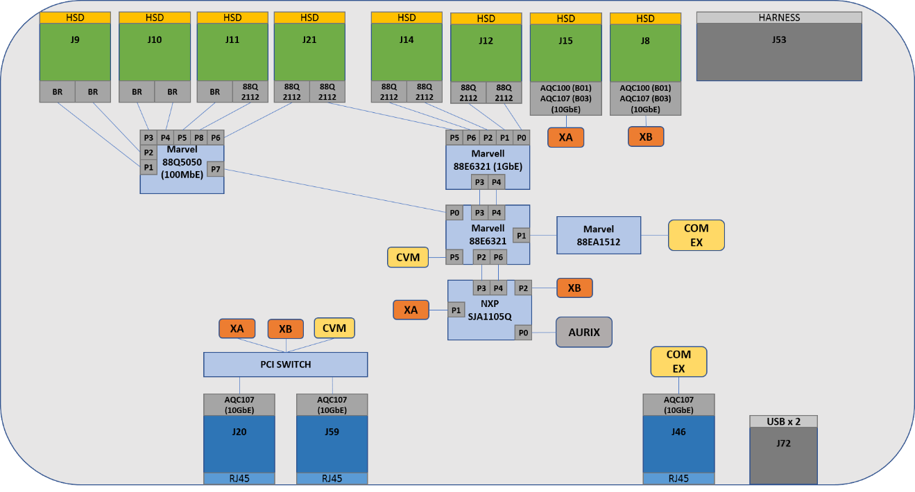
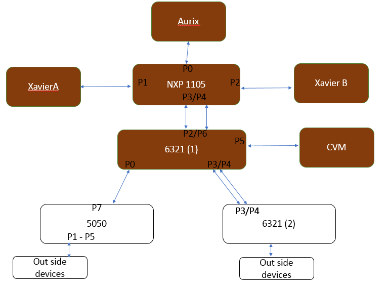
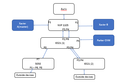
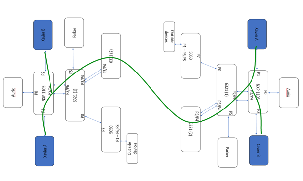
The 100M/1G networking architecture/topology of the DRIVE development platform along with all of the use case specific configurations enabled for VLAN, PTP is as follows:
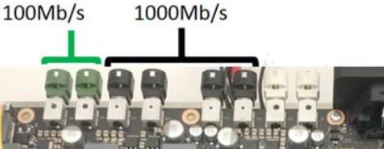
There are 12 total channels (100M/1G) that are exposed through 6 HSD ports as follows (i.e., 2 channels per port).
Ports are color coded based on the speed supported.
• Green ports = 100 Mbps channels
• Black ports = 1 Gbps channels
Note: | The one exception: Channel A of J11 only supports 100 Mbps. |
Port Roles
HSD Port | Color | Channel | Port Role | Speed Supported |
J9 | Green | Channel A | Slave | 100 Mbps |
Channel B | Slave | 100 Mbps |
J10 | Green | Channel A | Slave | 100 Mbps |
Channel B | Slave | 100 Mbps |
J11 | Black | Channel A | Slave | 100 Mbps |
Channel B | Slave | 1 Gbps |
J21 | Black | Channel A | Slave | 1 Gbps |
Channel B | Slave | 1 Gbps |
J14 | Black | Channel A | Slave | 1 Gbps |
Channel B | Slave | 1 Gbps |
J12 | Black | Channel A | Slave | 1 Gbps |
Channel B | Slave | 1 Gbps |
VLAN Configurations
VLAN 200 is enabled in Xavier A, Xavier B, CVM, NXP SJA1105Q switch, and Marvell 88EA6321 switch. When enabled:
• Provides a secure channel between multiple SoCs/VMs and between the SoC and MCU (AURIX).
• Makes safety MCU (AURIX) inaccessible from the outside.
• Used for MCU communication, including cameras, firmware updates, etc.
• Used by the OTA service for distribution of downloaded OTA specific images across VMs within the board.
• Virtualized to each VM (all Guest OS + IX, OTA, more may be added later)
gPTP/802.1AS Support on Linux
On DRIVE development platform Xavier, the Ethernet switches are configured in gPTP bypass mode for now (i.e., none of the switches recognize gPTP packets/frames as a special packet/frame and treat it as a normal Ethernet frame and forwards it to all ports of the switch).
This configuration can be leveraged for the following use-cases.
• Single Pegasus: Tegra- Aurix gPTP time synchronization
• Single Pegasus: Tegra-Tegra gPTP Time synchronization
• Dual Pegasus: Tegra-Tegra gPTP Time synchronization
All SoC side PTP related binaries are available at:
/home/nvidia/drive-t186ref-linux/samples/nvavb/daemons
Single Pegasus: SoC-Aurix gPTP time Synchronization
The platform support for 802.1AS conforming time synchronization messages for hardware time synchronization is as follows:
• From the AURIX MCU to both SoCs
• Using the PTP4l program on the SoC processors
• Using the AutoSAR 802.1AS clock master function on the AURIX processor
To start PTP sync between the AURIX processor and SoCs
1. Disable NTP on both Tegras. The following command disables NTP, which is persistent across reboots.
timedatectl set-ntp 0
2. In the AURIX console, enter the date in UNIX-style seconds.
For example:
date 0x77DA7A8F
3. Enable gPTP on AURIX:
gptpon
4. On both the Tegra A and Tegra B consoles, enter the following commands.
./phc2sys -s /dev/ptp0 -w -S 1.0 -O 0 &
/ptp4l -f ./gPTP_slave.cfg -p /dev/ptp0 -i eth0.200 -m -D -l 7
Single Pegasus: SoC-SoC gPTP Time Synchronization
The gPTP based time sync between on board nodes XA, XB and CVM is as follows.
PTP over non VLAN interface
1. Disable NTP on both SOCs. The following command disables NTP, which is persistent across reboots.
timedatectl set-ntp 0
2. On the Master SoC run these commands.
./phc2sys -s /dev/ptp0 -w -S 1.0 -O 0 &
./ptp4l -f ./gPTP.cfg -p /dev/ptp0 -i eth0 -m -D
3. On Slave SoCs run these commands.
./phc2sys -s /dev/ptp0 -w -S 1.0 -O 0 &
./ptp4l -f ./gPTP_slave.cfg -p /dev/ptp0 -i eth0 -m -D
PTP over VLAN interface (VLAN#200)
1. Disable NTP on both SoCs. The following command disables NTP, which is persistent across reboots.
timedatectl set-ntp 0
2. On the Master SoC run the following commands.
./phc2sys -s /dev/ptp0 -w -S 1.0 -O 0 &
./ptp4l -f ./gPTP.cfg -p /dev/ptp0 -i eth0.200 -m -D
3. On the Slave SoCs run the following commands.
./phc2sys -s /dev/ptp0 -w -S 1.0 -O 0 &
./ptp4l -f ./gPTP_slave.cfg -p /dev/ptp0 -i eth0.200 -m -D
Dual Pegasus: SoC-SoC gPTP Time Synchronization
The gPTP based time sync between nodes, Xavier A and Xavier B, of 2 Pegasus connected back to back is as follows.
PTP over non VLAN interface
1. Disable NTP on both SoCs. The following command disables NTP, which is persistent across reboots.
timedatectl set-ntp 0
2. On the Master SoC run these commands.
./phc2sys -s /dev/ptp0 -w -S 1.0 -O 0 &
./ptp4l -f ./gPTP.cfg -p /dev/ptp0 -i eth0 -m -D
3. On the Slave SoCs run these commands.
./phc2sys -s /dev/ptp0 -w -S 1.0 -O 0 &
./ptp4l -f ./gPTP_slave.cfg -p /dev/ptp0 -i eth0 -m -D
P3479 Network Topology
The P3479 network topology is as follows.