Image Encoder (nvmimg_enc)
The NvMedia sample application nvmimg_enc demonstrates how to use the NvMedia image encode API to encode H.264/H.265/VP9 bitstreams with the NVENC hardware engine.
The application consumes raw images in a single YUV file in the YUV color space. It produces compressed elementary streams in one of the following formats:
• H.264 with various configuration parameters
• Baseline up to Level 4.1
• Main profiles up to Level 4.1
• High profiles up to Level 4.1
• H.265 main profiles up to level 6.0 with various configuration parameters
• VP9 profile 0
nvmimg_enc can run in black box mode for a number of seconds specified on the command line. The specified number of seconds of bitstream is saved to the output bitstream file.
Architecture
This topic describes the architecture and flow of the application.
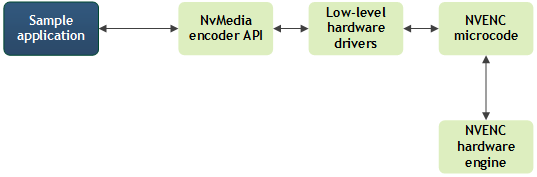
nvmimg_enc Stack Diagram
Component Descriptions
Name | Description |
nvmimg_enc (the sample application) | Calls the NvMedia encode APIs. On receipt of the headers and bitstream, packetizes or encrypts the encoded stream and saves the result to an output file. |
NvMedia encoder API | Calls the low-level hardware driver interface to issue encoding commands to NVENC microcode. |
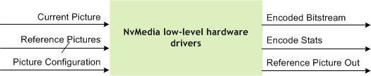
Low-level hardware driver | Writes out high level headers, including SPS, PPS, VUI and SEI. The driver creates and maintains reference picture surfaces, the output bitstream buffers, and the internal status buffers. For each input picture, the driver provides a configuration data structure (a picture setup) that contains encoder parameters along with the encode commands to the NVENC microcode. This structure contains: • Buffer information (current picture, reference pictures) • Sequence and picture parameter set information and rate control configuration • Other module configurations as needed |
NVENC microcode | Accesses the hardware engine to schedule the encoding commands, and return the encode status including bitstreams, statistics, etc. |
NVENC hardware engine | Handles slice header and data. |
NvMedia Low-Level Encode Driver Inputs and Outputs
Picture buffers must be in block linear format. Pitch linear input data is not supported due to inefficiency in the memory accesses.
Picture buffers must also be in NV12 format. The picture dimensions of the encoded streams are always in multiples of X pixels, where X is:
• 16 for H.264 encoding
• 32 for H.265 encoding
• 64 for VP9 encoding
If the input needs cropping, it is cropped at the right and bottom of the picture. If the input pictures horizontal/vertical are not X aligned, the application software must verify the padding on the right/bottom side to make it X aligned.
Running the Sample Application
The nvmimg_enc application supports an input file of type YUV.
To run the application
1. Prepare the input file.
• The input is a single YUV file.
• To encode YUV files, the InputFile parameter must specify the pathname on the command line or in a configuration file.
2. Create a configuration for the encoding process.
3. Follow the steps in Building and Running the NvMedia Samples.
4. Launch the application.
Command Line Switches
The format of the nvmimg_enc application command line is:
nvmimg_enc [-h] [-v] [-cf config.cfg] {[-sf config1.cfg]...[-sf configN.cfg]} {[-p EncParam1=EncValue1]..[ EncParamM=EncValueM]} -blackbox [num_second]
This table describes the command line switches:
Switch | Description | Default |
-h | Displays help text on for this application. | N/A |
-v <level> | Logging level. Value may be: • 0: Errors • 1: Warnings • 2: Info • 3: Debug | 0 |
-cf <config_file> | Specifies the base configuration file. | N/A |
-sf <config_file> | Specifies a specific configuration file. Any parameters provided in this file overwrite parameters specified in the base configuration file. | N/A |
-p <p1>=<v1>,… <pn>=<vn> | Sets parameter <p1> to the value <v1>… <pn> to value <vN>. Overrides parameters set through both configuration files. | N/A |
-blackbox <sec> | Enables black box mode with a recording time of <sec> seconds. | |
-crc gen <filename> | Generates golden CRC values and stores them in the specified file. | N/A |
-crc chk <filename> | Generates golden CRC values and checks them against the specified file. | N/A |
-id <id> | Specifies encoder instance ID. Value may be 0 or 1. | 0 |
Examples
This topic explains how to perform commonly performed tasks.
To encode to H.264/H265/VP9
• Enter the command:
./nvmimg_enc -cf enc_h264_sample.cfg
./nvmimg_enc -cf simple_h265_cif.cfg
./nvmimg_enc -cf simple_vp9_cif.cfg
The encoding is performed using parameters supplied in the configuration file.
The base configuration file specifies the input and output file information, but it is more convenient to use a specific configuration file (with the ‑sf option) for these parameters or pass them through the command line using -p option.
To run in blackbox mode
• Enter the command:
./nvmimg_enc -cf enc_h264_sample.cfg --blackbox <sec>
In black box mode, the application saves a specified number of seconds of bitstream in the output bitstream file. The number of seconds is specified by the ‑‑blackbox option.
In black box mode, the application forces the following encode parameters:
• GOP size = frame rate, which equals to 1 second encode time
• IDR period = GOP size
• H264RepeatSPSPPSMode = 2, SPS/PPS is repeated for every IDR frame
The settings guarantee that each GOP bitstream is decoded independently. The GOP size and IDR period can be set to half second encode time, or other values. The user application can choose values which fits the use case as desired.
To use a specific configuration file
• Enter the command:
./nvmimg_enc -cf enc_h264_sample.cfg -sf enc_h26x_aqiyo_specific.cfg
The encoding is performed using parameters supplied in the enc_h264_sample.cfg and enc_h26x_aqiyo_specific.cfg files. If a parameter is present in both files, the value in the specific configuration file enc_h26x_aqiyo_specific.cfg is used.
Configuration File Syntax
When you run nvmimg_enc you must provide it with a configuration file. A default configuration is available at:
home/nvidia/samples/nvmedia/img_enc/enc_h264_sample.cfg
The configuration file contains parameters with values, groups or sections of parameters, and optional comments.
Parameters
Each parameter must be on a separate line. A parameter line contains the following tokens:
• The parameter name
• An equal sign (“=”)
• A value
• An optional comment
Here is an example of a parameter with a comment:
InputFile = "configs/input.yuv" # File to encode
An unknown parameter in a configuration file does not cause a failure; the parameter is ignored. An ill-formed parameter line causes the application to fail.
Comments
A comment consists of a pound sign (a ‘#’) and any following text to the end of the line. A comment may appear at the end of any parameter line, or on a line by itself.
Sections
A section is a named group of parameters, containing a specific set of parameters. For example, the group RC_Params contains rate control parameters. You can define one or more RC_Params sections and use the parameter values they set by referring to them in the EPRateControlSectionIndex and EPPRCParamsIndex parameters, described later in this topic.
Available section types include:
• EncodePic_Params: Per-frame parameters
• EncodePicH264_Params: Specific H.264 per-frame parameters
• Payload: Different arrays of SEI payloads can be used for every picture in H.264 encoding
• EncodePicH265_Params: Consists of specific H.265 per frame parameters
• EncodePicVP9_Params: Specific VP9 per frame parameters
• PayloadH265: Different arrays of SEI payloads can be used for every picture in H.265 encoding
• RC_Params: Rate Control parameters
• QP_Params: Quantization parameters
Each section begins with a line in the form:
[<section name> <section number>]
The rest of the section consists of parameter values to be defined in the group. A specific set of parameters may be defined in each group, as shown in Configuration File Parameters.
For example, these lines define three QP_Params groups:
[QP_Params 1]
QPBSlice = 30 # Quant. parameter for B slices (0-51) - qpInterB
QPISlice = 28 # Quant. parameter for I Slices (0-51) - qpIntra
QPPSlice = 28 # Quant. parameter for P Slices (0-51) - qpInterP
[QP_Params 2]
QPBSlice = 40 # Quant. parameter for B slices (0-51) - qpInterB
QPISlice = 38 # Quant. parameter for I Slices (0-51) - qpIntra
QPPSlice = 38 # Quant. parameter for P Slices (0-51) - qpInterP
[QP_Params 3]
QPBSlice = 50 # Quant. parameter for B slices (0-51) - qpInterB
QPISlice = 48 # Quant. parameter for I Slices (0-51) - qpIntra
QPPSlice = 48 # Quant. parameter for P Slices (0-51) - qpInterP
Configuration File Parameters
Parameters that specify the length of an array, such as ExplicitFrameInvervalPatternLength or ExplicitFrameInvervalPattern, need not be set or may be set to 0. In either case the application uses the default array size, 1000.
General Configuration Parameters
This table describes the general configuration parameters:
Parameter | Description |
InputFile | Identifies the file sent to the encoder. |
InputFileFormat | Input file format. The value may be: • 0: IYUV • 1: YV12 • 3: IYUV444 • 4: IYUV420_10bit • 5: IYUV444_10bit |
OutputFile | Specifies the output file. |
StartFrame | Specifies the start frame for encoding. Encoding for StartFrame−1 is skipped. |
FramesToBeEncoded | Number of frames to encode. |
EPCodec | Specifies the video codec type. The value may be: • 0: H.264 codec • 1: H.265 codec • 2: VP9 codec |
EPSourceRectSpecified | When set to NVMEDIA_TRUE, constrains the source to be encoded to the rectangle specified by the EPSourceRect… parameters. For RBG input only. |
EPSourceRectX0 EPSourceRectY0 EPSourceRectX1 EPSourceRectY1 | Specify the source rectangle to encode, from the top left point [X0,Y0] to the bottom-right point [X1,Y1]. Meaningful only if EPSourceRectSpecified is set. |
EPRateControlSectionIndex | Index of the RC_params section to use for encoder initialization. |
ExplicitFrameIntervalPattern | Specifies the frame interval pattern. The values in the string represent the EncodePic_Params section to use for each frame. For example, if the given pattern is 123, then: • For frames 1, 4, 7, 10 etc... EncodePic_Params section 1 is used. • For frames 2, 5, 8, 11 etc... EncodePic_Params section 2 is used. • For frames 3, 6, 9, 12 etc... EncodePic_Params section 3 is used. |
ExplicitFrameIntervalPatternLength | Specifies the length of the interval pattern. |
Encode Configuration Parameters
This table describes the encode configuration parameters:
Parameter | Description |
EPEncodeWidth | Specifies the width of the encode. |
EPEncodeHeight | Specifies the height of the encode. |
EPFrameRateNum EPFrameRateDen | Specify the numerator and denominator for the frame rate to use for encoding, in frames/second. The frame rate is: EPFrameRateNum / EPFrameRateDen |
EPGopLength | Specifies the number of pictures in a GOP. If 0, keyframes are not inserted automatically. |
EPGopPattern | Specifies the GOP pattern. If GOP length is 0, Frame Interval Pattern must be set to IPP. Value may be: • 0: I • 1: IPP • 2: IBP • 3: IBBP |
EPEncodeRotation | Specifies the rotation of the input surface. Value may be: • 0x0: No rotation • 0x1: 90 degrees rotation • 0x2: 180 degrees rotation • 0x3: 270 degrees rotation |
EPEncodeMirroring | Specifies the mirroring of the input surface. Value may be: • 0x0: No mirroring • 0x1: Horizontal mirroring • 0x2: Vertical mirroring • 0x3: Horizontal and vertical mirroring |
EPMaxNumRefFrames | Specifies the maximum number of reference frames. Value may be: • EPMaxNumRefFrames =0 for I Only mode • EPMaxNumRefFrames =1 for IP mode • EPMaxNumRefFrames =2 for IBP mode |
Quantization Configuration Parameters
This table describes the quantization configuration parameters:
Parameter | Description |
QPBSlice | Specifies the Quantization parameter for B slices [0-51]. |
QPISlice | Specifies the Quantization parameter for I Slices [0-51]. |
QPPSlice | Specifies the Quantization parameter P Slices [0-51]. |
Rate Control Configuration Parameters
This table describes the rate control configuration parameters:
Parameter | Description |
RCMode | Specifies the rate control mode. Value may be: • 0x0 = Constant bitrate mode • 0x1 = Constant QP mode • 0x2 = Variable bitrate mode • 0x3 = Variable bitrate mode with MinQP |
RCAverageBitrate | Specifies the average bit rate in bits/second; used for encoding. |
RCMaxBitrate | Specifies the maximum bit rate for the encoded output. This is used in Variable Bit Rate (VBR) mode and is ignored for Constant Bit Rate (CBR) mode. |
RCVbvBufferSize | Specifies the VBV (HRD) buffer size in bits. Set to 0 to use the default VBV buffer size. |
RCVbvInitialDelay | Specifies the VBV(HRD) initial delay in bits. Set 0 to use the default VBV initial delay. |
RCEnableMinQP | Set to 1 if minimum QP is used for the rate control. |
RCEnableMaxQP | Set to 1 if maximum QP is used for the rate control. |
RCConstQPIndex | Specifies the initial QP_Params section index used for encoding. In Constant QP mode these values are used for all frames. |
RCMinQPIndex | Specifies the QP_Params section index used as the minimum QP values for rate control. |
RCMaxQPIndex | Specifies the QP_Params section index used as the maximum QP values for rate control. |
Per-Frame Encode Configuration Parameters
This table describes the per-frame encode configuration parameters:
Parameter | Description |
EPEencodePicFlags | Specifies the bitwise OR’ed encode picture flags. The flags are: • 0x1: Encodes the current picture as an Intra picture. • 0x2: Encodes the current picture as an IDR picture. This flag is valid when the picture type decision is made by the encoder (set EPPictureType to 0). • 0x4: Writes the sequence and picture header in the encoded bitstream of the current picture. • 0x8: Indicates the end of the input stream. • 0x10: Indicates a change in bit rate from the current picture onwards. • 0x20: Indicates that the user forced constant QP Rate control from the current picture onwards. • 0x40: Indicates a change in the rate control mode on the fly from current picture onwards. |
EPInputDuration | Specifies the duration of the input picture. |
EPPictureType | Specifies the input picture type. The client must set this parameter explicitly if it has not set the Enable PTD (picture type decision) to 1. The picture types are: • 0x00: Forward predicted picture • 0x01: Bi-directionally predicted picture • 0x02: Intra predicted picture • 0x03: IDR picture • 0x04: Bidirectionally predicted picture with only Intra MBs • 0x05: Picture is skipped • 0x06: First picture in intra refresh cycle • 0xFF: Picture type unknown |
EPH264PicParamsIndex | Codec specific parameters: EncodePicH264_Param section index to be used. |
EPRCParamsIndex | Rate control parameters: RC_Params section index to be used. |
H.264 Encode Configuration Parameters
This table describes the H.264 encode configuration parameters:
Parameter | Description |
H264Profile | Supported profiles are: • 0: Automatic profile selection • 66: Baseline profile • 77: Main profile • 88: Extended profile • 100: High profile |
H264Level | Specifies the encoding level. It is recommended that the client set the level to 0 to enable the NvMedia Encode interface to select the correct level. |
H264Features | Specifies the bitwise OR'ed configuration feature flags. The flags are: • ENABLE_OUTPUT_AUD (1 << 0) • ENABLE_INTRA_REFRESH (1 << 1) • ENABLE_DYNAMIC_SLICE_MODE (1 << 2) • ENABLE_CONSTRANED_ENCODING (1 << 3) |
H264IdrPeriod | Specifies the IDR interval. If not set, it defaults to the GOP length. A low latency application client must set IDR interval to 0 so that IDR frames are not inserted automatically. |
H264RepeatSPSPPSMode | Specifies the frequency of writing Sequence and Picture parameters. Value may be: • 0x0: Repeating SPS/PPS is disabled • 0x1: SPS/PPS is repeated for every intra frame • 0x2: SPS/PPS is repeated for every IDR frame |
H264NumSliceCountMinus1 | One less than the number of slices desired per frame. |
H264DisableDeblockingFilterIDC | Deblocking filter mode. Value may be 0, 1, or 2. |
H264IntraRefreshPeriod | Interval between successive intra refreshes, if Intra refresh is enabled and one-time intra refresh configuration is desired. If H264IntraRefreshPeriod is specified, the first IDR is encoded, and no more key frames are encoded. The client must set EPPictureType to 6 for the first picture of every intra refresh period. |
H264IntraRefreshCnt | Number of frames over which intra refresh occurs. |
H264MaxSliceSizeInBytes | Maximum slice size, in bytes, for dynamic slice mode. The client must enable dynamic slice mode to use this parameter. |
H264AdaptiveTransformMode | Specifies the Adaptive Transform Mode. Available modes are: • 0x0: The encoder driver automatically selects Adaptive Transform 8x8 mode. • 0x1: Adaptive Transform 8x8 mode disabled. • 0x2: Adaptive Transform 8x8 mode must be used. |
H264BdirectMode | Specifies the B Direct mode. Available modes are: • 0x0: Spatial B Direct mode • 0x1: Disable B Direct mode • 0x2: Temporal B Direct mode |
H264EntropyCodingMode | Specifies the entropy coding mode. Available modes are: • 0x0: Entropy coding mode is automatically selected by the encoder driver • 0x1: Entropy coding mode is CABAC • 0x2: Entropy coding mode is CAVLC |
H264MotionPredictionExclusionFlags | Specifies the bitwise OR’ed exclusion flags for motion prediction. Available flags are: • (1 << 0): Disable Intra 4x4 vertical prediction • (1 << 1): Disable Intra 4x4 horizontal prediction • (1 << 2): Disable Intra 4x4 DC prediction • (1 << 3): Disable Intra 4x4 diagonal down left prediction • (1 << 4): Disable Intra 4x4 diagonal down right prediction • (1 << 5): Disable Intra 4x4 vertical right prediction • (1 << 6): Disable Intra 4x4 horizontal down prediction • (1 << 7): Disable Intra 4x4 vertical left prediction • (1 << 8): Disable Intra 4x4 horizontal up prediction • (1 << 9): Disable Intra 8x8 vertical prediction • (1 << 10): Disable Intra 8x8 horizontal prediction • (1 << 11): Disable Intra 8x8 DC prediction • (1 << 12): Disable Intra 8x8 diagonal down left prediction • (1 << 13): Disable Intra 8x8 diagonal down right prediction • (1 << 14): Disable Intra 8x8 vertical right prediction • (1 << 15): Disable Intra 8x8 horizontal down prediction • (1 << 16): Disable Intra 8x8 vertical left prediction • (1 << 17): Disable Intra 8x8 horizontal up prediction • (1 << 18): Disable Intra 16x16 vertical prediction • (1 << 19): Disable Intra 16x16 horizontal prediction • (1 << 20): Disable Intra 16x16 DC prediction • (1 << 21): Disable Intra 16x16 plane prediction • (1 << 22): Disable Intra chroma vertical prediction • (1 << 23): Disable Intra chroma horizontal prediction • (1 << 24): Disable Intra chroma DC prediction • (1 << 25): Disable Intra chroma plane prediction • (1 << 26): Disable Inter L0 partition 16x16 prediction • (1 << 27): Disable Inter L0 partition 16x8 prediction • (1 << 28): Disable Inter L0 partition 8x16 prediction • (1 << 29): Disable Inter L0 partition 8x8 prediction |
H.264 VUI Configuration Parameters
This table describes the H.264 VUI configuration parameters:
Parameter | Description |
VUIAspectRatioInfoPresentFlag | A value of 1 indicates that the aspect ratio information is present. |
VUIAspectRatioIDC | Specifies the sample aspect ratio of the luma samples. |
VUIAspectSARWidth | Specifies the horizontal size of the sample aspect ratio. |
VUIAspectSARHeight | Specifies the vertical size of the sample aspect ratio. |
VUIOverscanInfoPresentFlag | A value of 1 indicates that overscan info is present. |
VUIOverscanInfo | Specifies overscan information, as defined in Annex E of the ITU-T Specification. |
VUIVideoSignalTypePresentFlag | If set to 1, specifies that Video Format, Video Full Range Flag and Color Description Present Flag are present. |
VUIVideoFormat | Specifies the source video format, as defined in Annex E of the ITU-T Specification. |
VUIVideoFullRangeFlag | Specifies the output range of the luma and chroma samples, as defined in Annex E of the ITU-T Specification. |
VUIColourDescriptionPresentFlag | A value of NVMEDIA_TRUE indicates that the color primaries, transfer characteristics, and color matrix are present. |
VUIColourPrimaries | Specifies the color primaries for converting to RGB, as defined in Annex E of the ITU-T Specification. |
VUITransferCharacteristics | Specifies the opto-electronic transfer characteristics to use, as defined in Annex E of the ITU-T Specification. |
VUIMatrixCoefficients | Specifies the matrix coefficients used to derive the luma and chroma from the RGB primaries, as defined in Annex E of the ITU-T Specification. |
H.264 Payload Configuration Parameters
This table describes the H.264 payload configuration parameters:
Parameter | Description |
H264PayloadSize | SEI payload 1 size in bytes. SEI payload must be byte aligned, as described in Annex D of the H.264 Specification. |
H264PayloadType | SEI payload 1 types and syntax is available in Annex D of the H.264 Specification. |
H264Payload | Payload 1 data. |
H.264 Per-Frame Encode Configuration Parameters
This table describes the H.264 per-frame encode configuration parameters. These are in addition to the Per-Frame Encode Configuration Parameters. These parameters must be sent on a per-frame basis.
Parameter | Description |
H264PayloadArraySize | Size of Payload Array. |
H264PayloadArrayIndexes | Array of Payload section indexes to be used. |
H.265 Configuration Parameters
This table describes the H.265 configuration parameters:
Parameter | Description |
H265Profile | Supported profiles are: 0: Automatic profile selection (unsupported) 1: Main profile (supported) 2: Main 10 profile (unsupported) |
H265Level | Specifies the encoding level. It is recommended that the client set the level to 0 to enable the NvMedia Encode interface to select the correct level. |
H265Features | Specifies bitwise OR'ed configuration feature flags. The flags are: • ENABLE_OUTPUT_AUD (1 << 0) • ENABLE_INTRA_REFRESH (1 << 1) • ENABLE_DYNAMIC_SLICE_MODE (1 << 2) • ENABLE_CONSTRANED_ENCODING (1 << 3) |
H265IdrPeriod | Specifies the IDR interval. If not set, defaults to the GOP Length. A low latency application client can set the IDR interval to 0 so that IDR frames are not inserted automatically. |
H265RepeatSPSPPSMode | Specifies the frequency of writing Sequence and Picture parameters. Available values are: • 0x0: Repeating SPS/PPS is disabled • 0x1: SPS/PPS is repeated for every intra frame • 0x2: SPS/PPS is repeated for every IDR frame |
H265NumSliceCountMinus1 | One less than the number of slices desired per frame. |
H265DisableDeblockingFilterIDC | Deblocking filter mode. Possible values are 0 and 1. |
H265IntraRefreshPeriod | The interval between successive intra refreshes, if Intra refresh is enabled, and one time intra refresh configuration is desired. If H265IntraRefreshPeriod is specified, the first IDR is encoded, and no more key frames are encoded. The client must set EPPictureType to 6 for the first • picture of every intra refresh period. |
H265IntraRefreshCnt | Specifies the number of frames over which intra refresh occurs. |
H265MaxSliceSizeInBytes | Specifies the maximum slice size, in bytes, for dynamic slice mode. The client must enable dynamic slice mode to use this parameter. |
H.265 VUI Configuration Parameters
This table describes the H.265 VUI configuration parameters:
Parameter | Description |
H265VUIAspectRatioInfoPresentFlag | A value of 1 indicates that aspect ratio information is present. |
H265VUIAspectRatioIDC | Specifies the value of the sample aspect ratio of the luma samples. |
H265VUIAspectSARWidth | Horizontal size of the sample aspect ratio. |
H265VUIOverscanInfoPresentFlag | A value of 1 indicates that overscan information is present. |
H265VUIOverscanInfo | Specifies overscan information, as defined in Annex E of the ITU-T Specification. |
H265VUIVideoSignalTypePresentFlag | A value of 1 indicates that Video Format, Video Full Range Flag, and Color Description Present Flag are present. |
H265VUIVideoFormat | Specifies the source video format, as defined in Annex E of the ITU-T Specification. |
H265VUIVideoFullRangeFlag | Specifies the output range of the luma and chroma samples, as defined in Annex E of the ITU-T Specification. |
H265VUIColourDescriptionPresentFlag | A value of NVMEDIA_TRUE indicates that the color primaries, transfer characteristics, and color matrix are present. |
H265VUIColourPrimaries | Specifies color primaries for converting to RGB, as defined in Annex E of the ITU-T Specification. |
H265VUITransferCharacteristics | Specifies the opto-electronic transfer characteristics to use, as defined in Annex E of the ITU-T Specification. |
H265VUIMatrixCoefficients | Specifies the matrix coefficients to use to derive the luma and chroma from the RGB primaries, as defined in Annex E of the ITU-T Specification. |
H.265 Payload Configuration Parameters
This table describes the H.265 payload configuration parameters:
Parameter | Description |
H265PayloadSize | SEI payload 1 size in bytes. SEI payload must be byte aligned, as described in Annex D of the ITU‑T Specification. |
H265PayloadType | SEI payload 1 types and syntax are available in Annex D of the ITU‑T Specification. |
H265Payload | Payload 1 data. |
H.265 Per-Frame Encode Configuration Parameters
This table describes the H.265 per-frame encode configuration parameters. These parameters must be sent on a per frame basis.
Parameter | Description |
EPH265PicParamsIndex | Codec specific parameters: EncodePicH265_Params section index to be used. |
H265PayloadArrayIndexes | Array of Payload section indexes to be used. |
H265PayloadArraySize | Size of Payload Array. |
VP9 Configuration Parameters
This table describes the VP9 configuration parameters:
Parameter | Description |
VP9Features | Specifies bitwise OR'ed configuration feature flags. The flags are: • ENABLE_LOOP_FILTER_PARAMS (1 << 0), • ENABLE_QUANTIZATION_PARAMS (1 << 1), • ENABLE_TRANSFORM_MODE (1 << 2), • ENABLE_HIGH_PRECISION_MV (1 << 3), • DISABLE_ERROR_RESILIENT (1 << 4), • ENABLE_PROFILING (1 << 5), • INIT_QP (1 << 6), • QP_MAX (1 << 7) |
VP9IdrPeriod | Specifies the IDR interval. If not set, this is made equal to the GOP length. Low latency application client can set IDR interval to 0 so that IDR frames are not inserted automatically. Default value = 17 |
VP9 Per-Frame Encode Configuration Parameters
This table describes the VP9 per-frame encode configuration parameters. These parameters must be sent on a per frame basis.
Parameter | Description |
EPVP9PicParamsIndex | Codec specific parameters: EncodePicVP9_Params section index to be used. |