Understanding Security
- Acronyms and Abbreviations
NVIDIA DRIVE™ OS security services ensure the confidentiality of critical system secrets such as root keys and other device configuration information. They are also responsible for providing user-space applications running in the Guest OS, the ability to offload cryptographic operations on-to SoC SE hardware. These services rely on the isolation provided by the virtualization system.
This section describes the functionality and possible customization for these security services and is broadly divided into sub-sections.
Refer to the appropriate sub-section for detailed information on the various services:

Sub-section | Section Description |
Contains information pertinent to the NVIDIA secure boot flow, the types of HW fuses available on the platform, and hardware fusing responsibilities. | |
Contains general information about the NVIDIA Security Engine, including how to use it for cryptographic acceleration in a virtualized environment. | |
Trusted OS | Contains general information about the operating system that runs in the Trusted Execution Environment to isolate and manage device secrets. Additionally, this section provides instruction to add custom Trusted applications and generate a custom encrypted key store. |
Contains general information about Guest OS security configurations that are customized by developers. | |
Contains general information about advanced debug capabilities that are available on the platform after the production fuses are blown. |
Acronyms and Abbreviations
The following acronyms are used throughout this section.
Term | Definition |
ATF | ARM trusted firmware |
BCT | Boot Configuration Table |
BDT | Boot Device Tree |
BR | BootROM |
BR-BCT | BootROM Boot Configuration Table |
CA | Client Applications |
CBC | Cipher Block Chaining |
CMAC | a block of Cipher-based Message Authentication code algorithm |
EKS | Encrypted Key Store |
GP API | Global Platform Application Programming Interface |
HW | Hardware |
JTAG | Joint Test Action Group IEEE 1149.1 Standard Test Access Port and Boundary-Scan Architecture |
KEK | Key Encryption Key |
LUKS | Linux Unified Key Setup disk encryption specification |
ODM | Original Design Manufacturing |
OEM | Original Equipment Manufacturer |
OpenSSL | A general purpose cryptography library that provides an open source implementation of the Secure Sockets Layer protocol. |
OS | Operating System |
OSC | Oscillator |
OTA | Over-the-Air |
PCT | Platform Configuration Table |
PKC | Public Key Cryptography |
PolarSSL | also known as ARM-mbed |
REE | Rich Execution Environment |
ROM | Read-only Memory |
RPMB | Replay protected memory block |
RSA | An encryption mechanism that uses public and private keys. |
RSASSA-PSS | RSA Signature Scheme with Appendix- Probabilistic Signature Scheme (cryptography) |
SBK | Secure Boot Key |
SDK/PDK | Software Development Kit / Platform Development Kit |
SDRAM | Synchronous Dynamic Random Access Memory |
SE | Security Engine Hardware |
SS | Secure Storage |
TA | Trusted Applications |
TEE | Trusted Execution Environment |
TOS | Trusted Operating System |
TSC | Tegra Secure Counter |
TZVault | NVIDIA TOS variant (targeted for Safety systems) |
UID | Unique Identification |
UUID | Universal Unique Identification |
VM | Virtual Machine |
Secure Boot and Hardware Fuses
The following sections describe secure boot and hardware fuses.
Root of Trust and Chain of Trust
In a chain of trust, the trustworthiness of each layer of software that composes the chain is guaranteed by the previous layer, until reaching the root of the chain, or root of trust. Immutability and formal verification provide the foundation for a root of trust. An example is the code present in read-only memory (ROM). The root of trust initiates the chain of trust.
A chain of trust, for example, can include: bootROM to boot loader to TrustZone operating system.
NVIDIA Chain of Trust
The bootROM combined with NVIDIA-programmed fuses constitute the root of trust in the boot process. BootROM is the instruction read-only memory written by NVIDIA, embedded into the hardware, and executed first upon every boot. BootROM initiates the chain of trust and hands it off to the ODM by authenticating and then invoking ODM-owned code (boot loader) with an ODM fuse programmed key.
Secure Boot
Secure boot:
• Must be implemented and enabled during manufacturing.
• Cannot be enabled over OTA or in the field.
• Defines a chain of trust.
• Is supported by hardware from power on to boot ROM to boot loader.
• Must be implemented by the boot loader.
NVIDIA DRIVE devices establish the chain of trust with these boot sequences:
• PKC-protected boot sequence
• RSA 3K signature
• EdDSA signature
The FUSE_BOOT_SECURITY_INFO on NVIDIA DRIVE devices determines which sequence is used. The information in the FUSE_BOOT_SECURITY_INFO bits is as follows:
• Bit[7, 1:0]: authentication scheme
• x10b: PKC-protected boot sequence with RSA 3K key pairs
• 111b: PKC-protected boot sequence with EdDSA key
Fuse Burning Responsibilities
Applications can program a fuse by applying voltage using fuse burning routines found in the boot loader and the kernel APIs. The fuses and ownership required for Secure Boot are as follows:
• NVIDIA Programmed
• 128-bit Unique ID (UID), no two Tegra chips have the same UID.
• NVIDIA production mode
• Customer Programmed and Owned
• FUSE_BOOT_SECURITY_INFO
• Public key encoded as SHA-256.
• ODM Production Mode (FUSE_SECURITY_MODE)
Caution: | ODM Production Mode fuse disables further fuse burning except reserved ODM fuses. Therefore, burn the ODM Production Mode fuse last. |
Fusing a Board with a PKC Public Key Hash
Devices that implement secure boot with PKC protection have certain requirements regarding blowing fuses and boot loader signing. This topic explains how to fuse the PKC public key hash.
To fuse a board with a PKC public key hash you must have performed the following tasks:
1. Choose one of these options:
Note: | EdDSA private key can be generated using OpenSSL Version 1.1.1. OpenSSL Version 1.1.x changed its default digest from MD5 to SHA256. Adding the -md md5 option for encryption and decryption resolves unexpected behavior. |
Generating a PKC Key Pair Using OpenSSL
Use these procedures to generate a PKC key pair using OpenSSL.
To install OpenSSL
1. If you are generating only the RSA pair, install the OpenSSL package with the command:
sudo apt-get install openssl
To generate an EdDSA key pair for NVIDIA DRIVE AGX Xavier
1. Download and extract the OpenSSL EdDSA/ED25519 key support OpenSSL Version 11.1 Pre-8 available at:
https://openssl.org
2. Build OpenSSL as follows:
• In a terminal window, navigate to the directory where you extracted OpenSSL and execute these commands:
./config
make
• Once the OpenSSL build is completed, copy libcrypto.so* and libssl.so* to your local /lib/ directory.
• To generate the keys, execute OpenSSL from the application folder in the directory where you extracted OpenSSL.
For more information, consult the OpenSSL README file in the extracted source directory.
3. Generate EdDSA private key with the command:
openssl genpkey -algorithm Ed2551 --out keyfile.pem
You are now ready to generate the signed binaries and PKC hash.
To generate a PKC hash
1. Run these commands on the host to generate a public key (for EdDSA) and a PKC hash.
• For NVIDIA DRIVE AGX Xavier RSA 3072-bit keys:
$# cd drive-t186ref-foundation
$# ./tools/host/flashtools/flash --pkc <private_key_filename> --chip 0x19
Where <private_key_filename> depends on the tool used to generate the key.
• For PolarSSL, use rsa_priv.txt.
• For OpenSSL, use rsa_priv.pem.
And where:
• <public_key_filename> is the name you want to give the public key file.
• For NVIDIA DRIVE AGX Xavier EdDSA:
$ cd drive-t186ref-foundation
$ ./tools/host/flashtools/flash/tegrasign_v2 --key <private_key_filename> --pubkeyhash <public_key_filename>
$ ./tools/host/flashtools/flash/tegrakeyhash –ed25519 <public_key_filename> --chip 0x19
Where:
• <public_key_filename> is the name you want to give the public key file.
• <private_key_filename> is depends on the tool used to generate the key. For OpenSSL, use keyfile.pem.
Example Output
Example of the output of the tegrakeyhash command, when a PolarSSL key is supplied, is as follows:
# PKC key in PolarSSL format
# sha256 hash:
# bytes:
# 0xef, 0xcd, 0xab, 0x89, 0x67, 0x45, 0x23, 0x01,
# 0xef, 0xcd, 0xab, 0x89, 0x67, 0x45, 0x23, 0x01,
# 0xef, 0xcd, 0xab, 0x89, 0x67, 0x45, 0x23, 0x01,
# 0xef, 0xcd, 0xab, 0x89, 0x67, 0x45, 0x23, 0x01,
#
# tegra-fuse format: 0x0123456789abcdef0123456789abcdef0123456789abcdef0123456789abcdef
#
# fuse bypass format:
# FAB_ENTRY(PUBLIC_KEY0, PUBLIC_KEY0, 0x89abcdef),
# FAB_ENTRY(PUBLIC_KEY1, PUBLIC_KEY1, 0x01234567),
# FAB_ENTRY(PUBLIC_KEY2, PUBLIC_KEY2, 0x89abcdef),
# FAB_ENTRY(PUBLIC_KEY3, PUBLIC_KEY3, 0x01234567),
# FAB_ENTRY(PUBLIC_KEY4, PUBLIC_KEY4, 0x89abcdef),
# FAB_ENTRY(PUBLIC_KEY5, PUBLIC_KEY5, 0x01234567),
# FAB_ENTRY(PUBLIC_KEY6, PUBLIC_KEY6, 0x89abcdef),
# FAB_ENTRY(PUBLIC_KEY7, PUBLIC_KEY7, 0x01234567),
2. The tegra-fuse format can be used in FSKP Fuse Burning Tool.
<fuse name="PublicKeyHash" size="32" value="0x0123456789abcdef0123456789abcdef0123456789abcdef0123456789abcdef"/>
Fusing the Board with the Secure Keys
The BSP provides Fuse Burning Tool for fusing the board with the PKC hash. Sample XML files to burn secure keys and enable PKC protection are as follows.
For NVIDIA DRIVE AGX Xavier RSA:
<genericfuse MagicId="0x45535546" version="1.0.0">
<fuse name="PublicKeyHash" size="32" value="0x0123456789abcdef0123456789abcdef0123456789abcdef0123456789abcdef"/>
<fuse name="BootSecurityInfo" size="4" value="0x2"/>
<fuse name="SecurityMode" size="4" value="0x1"/>
</genericfuse>
For NVIDIA DRIVE AGX Xavier EdDSA:
<genericfuse MagicId="0x45535546" version="1.0.0">
<fuse name="PublicKeyHash" size="32" value="0x0123456789abcdef0123456789abcdef0123456789abcdef0123456789abcdef"/>
<fuse name="BootSecurityInfo" size="4" value="0x83"/>
<fuse name="SecurityMode" size="4" value="0x1"/>
</genericfuse>
Warning: | If used, the SecurityMode must be the last fuse command in the XML file. The FSKP fuse burning tool burns fuses in the order specified in the XML file. After burning the SecurityMode fuse, it disables fuse burning. |
To set up the platform for secure boot
1. Generate the PKC Key and ensure ODM production fuse is burned.
• Ensure the ODM production fuse is burned.
2. Consult the instructions for fusing the secure keys in Factory Secure Key Provisioning.
Warning: | This step is irreversible, ensure that: • The PKC key pair is a valid key pair. • The PKC key pair is stored in a secure location, because all the binaries must be signed with the private key. |
3. Sign and flash the binaries.
Use “-p <private_key_filename>” option when running the bootburn.sh script.
Where <private_key_filename> depends on the tool used to generate the key:
• For PolarSSL, use rsa_priv.txt for RSA.
• For OpenSSL, use rsa_priv.pem for RSA, or keyfile.pem for EdDSA.
BR BCT Signing and Hash Compression
The data section in BR BCT is signed with a zero-key SHA256, and the last 16 bytes of this section are used to store the hash value. If a value has never been stored there, those bytes contain a known pattern that indicates to the update tool that no hash value is present.
During boot the hash value is computed and compared with the stored value. If the update tool does not find a matching stored value, or if it finds that no value is present, the tool stores the computed value.
Public-Key Cryptography
Public Key Cryptography relies on a public and private key pair, allowing the manufacturer to sign a boot loader and BCT with its private key, never needing to disclose the private key at any time during the manufacturing process. The public key, which is used to verify the digital signature of the boot loader and BCT, gets stored on the secondary boot device or embedded into the boot loader and BDT images. Using PKC allows devices to be manufactured at facilities that are not secure.
Secure Boot Details with PKC Protection
The PKC-protected boot sequence is as follows. The sequence is part of the NVIDIA Secure Solutions infrastructure, which includes:
• NvImageGen utility—manages the RSA key pairs or EdDSA key and produces secure data that includes the BCT, which can contain the BCT signatures and the public key.
• Boot ROM—Tegra devices contain a boot ROM that adds support for the PKC-protected boot sequence.
The NVIDIA Secure Solutions infrastructure and the PKC-protected boot sequence ensure that the device is flashed with a BCT and boot loader that the OEM/Integrator has signed. The signature uses the private key from the RSASSA-PSS key pair or EdDSA key. The boot ROM validates the signatures and boot loader with the public key, which is stored in BCT. An SHA-256 hash of the public key is fused into the device.
The fused public key establishes the chain of trust for authenticating the BCT and boot loader. With the fused public key, the boot ROM verifies that the BCT and boot loader are from the OEM and have not modified after they are signed.
A fuse on your board selects the PKC-protected boot sequence.
• If the fuse is set to 0x2 (FUSE_BOOT_SECURITY_INFO[7, 1:0]=2), the boot ROM uses the PKC-protected boot with RSA 3K signature.
• Similarly, if the fuse is set to 0x83, the boot ROM uses the PKC-protected boot with EdDSA signature.
• If bit 2 of the fuse is set to 0x1, the boot ROM uses the SBK-protected boot sequence.
PKC Secure Boot Requirements
For the PKC-secured boot process to be used, these conditions must be met. These requirements must be implemented in production because secure boot cannot be implemented using OTA onto previously non-secure boot devices.
• The fused PKC public key hash must be non-zero.
• The FUSE_BOOT_SECURITY_INFO[7,1:0] must set to 0x2 or 0x83.
Where:
• 0x2 is for RSA 3K
• 0x83 is for EdDSA
• The OEM must amend the BCT and the software components with public keys and digital signatures. Use the NvImageGen for this task.
• The ODM Production Mode, Security Mode, fuse must be burned and it must be the last fuse to be burned.
RSA Validation of the BCT and Boot Loader
The boot ROM verification process that ensures the BCT is from the OEM, is as follows. The boot ROM uses this sequence when the conditions in PKC Secure Boot Requirements are satisfied.
Note: | SHA-256 is the hash function used during any RSASSA-PSS operations (signature verification) in the steps below. As recommended by PKCS #1 v2.1: RSA Cryptography Standard, the manufacturer must also use SHA-256 as the same hash function applied to the message. In addition, the salt length used in the RSASSA-PSS signature verification and signature generation is the length of SHA-256 hash. |
1. The boot ROM loads the RSA public key modulus into the PKC SE key slot.
2. The boot ROM reads and validates the BCT:
• Reads the BCT from secondary storage and validates the public key by computing SHA-256 hash and comparing it with values in fuses. If they match, the public key is stored to the PKC SE slot. The public key is used to decrypt the BCT and boot loader signature. Subsequent steps use fused public key to identify the decrypted version of the fused public key.
The public key as well as the RSASSA-PSS signature S is contained in the BCT.
Note: | The public exponent e is assumed to always be 0x10001, so it is not stored. • For NVIDIA DRIVE AGX Xavier, the public key is 3072 bits. |
• The boot ROM performs a RSASSA-PSS-VERIFY signature verification operation of the BCT using the verified public key. This step validates the RSASSA-PSS signature S of the BCT. If the result of the signature verification step is a valid signature, it continues the secure boot process. If the hash comparison fails, the boot ROM retries this step with the remaining 63 redundant copies of the BCT that are supported before the boot ROM gives up and goes to RCM.
Note: | Some copies of the BCT may have failed the public key hash compare in the beginning of Step 2, so the number of redundant copies of the BCT still available may be less than the actual number of redundant copies of the BCT written to secondary storage. |
3. The Boot ROM reads and validates the boot loader:
• Reads the boot loader data from secondary storage and uses the RSA public key to decrypt the boot loader signature.
• The RSASSA-PSS signature S gets stored in the beginning of the boot loader image in the generic signature header. The BR performs a RSASSA-PSS-VERIFY signature verification operation of the boot loader. If the result of the signature verification step is a valid signature, it continues the secure boot process and the chain-of-trust is transferred to the validated boot loader. If the signature verification fails, the BR retries this step for up to three additional copies of the boot loader from secondary storage that are supported before the boot ROM gives up and goes to RCM.
Note: | NVIDIA DRIVE AGX Xavier: the signature is verified on the image header; where the header embedded the hash value of the bootloader image. |
4. The boot loader is copied to the destination, generally to SDRAM due to size.
5. The boot ROM locks down security features, clears out state information, and then transfers control to the boot loader.
6. The boot loader continues the root of trust:
• Write protects mass storage location of the boot loader and OS.
• Passes execution to the validated OS image.
EdDSA Authentication of the BCT and Boot Loader
Use these instructions to understand the process the boot ROM uses to verify that the BCT is trusted. The boot ROM performs this process when the conditions in PKC Secure Boot Requirements are satisfied.
Note: | NVIDIA DRIVE AGX Xavier: • Support is provided for EdDSA operations (signature verification) using SHA-512 hash function. • Curve25519 is the elliptic curve supported. |
1. The boot ROM reads and authenticates the BCT:
• First, the boot ROM reads the BCT from secondary storage and verifies the public key by computing the SHA-256 hash and comparing it with the values in the fuses. If they match, the public key is used to verify the BCT and boot loader signature.
• Then the boot ROM verifies the BCT’s EdDSA signature using the verified public key. If the signature is verified, the secure boot process continues. If either the SHA-256 hash comparison or the signature comparison fails, the boot ROM retries this step with the remaining 63 redundant copies of the BCT. If verification fails with all 63 copies, the boot ROM gives up and goes to RCM.
2. The Boot ROM reads and verifies the boot loader:
• First, the boot ROM reads the boot loader data from secondary storage and uses the EdDSA public key to verify the boot loader signature.
• Next, the boot ROM stores the EdDSA signature at the beginning of the boot loader image in the generic signature header.
• The boot ROM then verifies the boot loader using the EdDSA signature. If the signature is verified, the secure boot process continues, and the chain-of-trust is transferred to the verified boot loader. If signature verification fails, the boot ROM retries this step for up to three additional copies of the boot loader from secondary storage before it gives up and goes to RCM.
Note: | NVIDIA DRIVE AGX Xavier: the signature is verified on the image header; where the header embedded the hash value of the bootloader image. |
3. The boot ROM copies the boot loader to the destination, generally an SDRAM, and then transfers control to the boot loader.
4. The boot loader continues the root of trust by:
• Protecting the mass storage location of the boot loader and OS.
• Passing execution to the validated OS image.
RSA Secured USB Recovery Mode
RCM can be secured with PKC-based authentication, using the same general authentication flow described in RSA Validation of the BCT and Boot Loader. Use these modifications when securing RCM with an RSA signature:
1. The boot ROM receives an RCM message.
2. The boot ROM authenticates the RSA public key from the RCM header by comparing the SHA-256 hash of the public key in the RCM header with the SHA-256 hash of the public key stored in fuses.
• If the public key is authenticated, the boot ROM loads the public key into an RSA key slot for RSASSA-PSS-VERIFY operations.
• If the public key in the RCM message header fails authentication, it returns a validation failure message to the USB host. The public key in subsequent RCM messages will not be validated. The boot ROM will use the authenticated public key already loaded in the SE RSA key slot.
3. The boot ROM validates the RCM message with an RSASSA-PSS-VERIFY operation.
• If the authentication of the RCM message fails, it returns a validation failure message to the USB host.
• If the authentication of the RCM message passes, it executes the RCM command as indicated in the RCM header.
• If the RCM message is not a “Download & Execute” command, the boot ROM will receive more RCM messages sent from the USB host.
• If the RCM message is a “Download & Execute” command, the boot ROM will exit, and execute the RCM payload.
Note: | As part of the regular boot ROM exit path, the RSA key slots are zeroed out. |
EdDSA Secured USB Recovery Mode
RCM can be secured with EdDSA authentication using the same general authentication flow described in EdDSA Authentication of the BCT and Boot Loader. Use these modifications when securing RCM with EdDSA:
1. The boot ROM receives an RCM message.
The boot ROM authenticates the public key from the RCM header by comparing the SHA-256 hash of the public key in the RCM header with the SHA-256 hash of the public key stored in the fuses.
• If the public key is authenticated, the boot ROM uses the public key for EdDSA operations.
• If the public key in the RCM message header fails authentication, the boot ROM returns a validation failure message to the USB host.
2. The boot ROM validates the RCM message with an EdDSA operation.
• If RCM message authentication fails, the boot ROM returns a validation failure message to the USB host.
• If RCM message authentication succeeds, the boot ROM executes the RCM command indicated in the RCM header.
• If the RCM message is not a “Download & Execute” command, the boot ROM receives more RCM messages sent from the USB host.
• If the RCM message is a “Download & Execute” command, the boot ROM exits, and the RCM payload executes.
Security Engine Key Slot Usage
The Security Engine key slots that are loaded with various keys by BootROM are as follows:
Key | Key Slot |
KEK0 | 13 |
KEK1 | 12 |
KEK2 | 11 |
KEK256 | 13 |
SBK | 14 |
SSK | 15 |
Security Engine
The Security Engine is a general-purpose hardware accelerator for performing Cryptographic Operations and it is virtualized through SE Virtualization Software. SE Virtualization software architecture is based on para-virtualization technique, where a dedicated virtualization system partition (a.k.a. SE resource manager server OR SE Server) is responsible for managing the security engine hardware and a message based interface is exposed to the virtual machines for requesting security engine services.
Refer to the PKCS#11 Interface section for more details on performing HW offload of cryptographic operations using Security Engine.
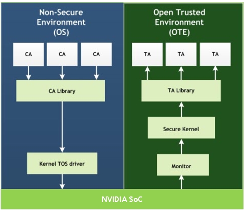
Trusted OS
All software that runs in an isolated trusted execution environment, based on ARM TrustZone technology, is collectively called Trusted OS.
Trusted OS includes software components that provide confidentiality of critical security assets on the DRIVE platform. For more information on ARM TruztZone technology, consult: https://www.arm.com/products/security-on-arm/trustzone
Terms relevant to Trusted OS are as follows:
• Rich Execution Environment (REE): consists of kernel drivers, client applications, and some user space libraries. All requests originate from the CAs and the kernel helps calling into TrustZone by issuing an smc command.
• ARM Trusted FW (ATF): secure monitor firmware. This handles all communications between the non-secure and secure worlds by activating and deactivating the appropriate environment and by routing function calls to the appropriate Trusted OS callbacks.
• Trusted Environment trusted OS: consists of trusted kernel, trusted applications (TAs), which act as secure service providers, and a set of kernel and user space libraries.
Typically, a TA running in the Trusted Execution Environment (TEE) has a non-secure client application (CA) running in the Rich Execution Environment (REE). All communication from REE to TEE is synchronous and driven by the REE.
To communicate with a specific TA, specify the UUID of that TA as one of the input parameters, in addition to any other context that needs to be passed across. It is worth noting that TA -> TA communication is also supported inside the trusted OS.
NVIDIA Trusted OS has two distinct versions, namely:
• Trusty - legacy version based on Android Open Source Project
• TZVault - latest version developed by NVIDIA
Warning: | Trusty will be removed in future release. Only TZVault shall be supported as the Trusted OS. |
The abbreviation “TOS” is typically valid for both these versions, since they are both Trusted Operating Systems. But the remainder of this document will specify the version being talked about explicitly to ensure there is no ambiguity.
Trusty (Legacy)
NVIDIA platforms use a customized version of Trusty as the Trusted OS. For more information consult:
Important: | Trusty will be removed in future release. Only TZVault shall be supported as the Trusted OS. |
A high-level architecture of the Trusty based Trusted OS is as follows.
Trusted OS – Trusty supports the following TAs:
• Secure storage
• Secure counter
• Crypto services such as AES variants, RSA modes, various SHA modes, RNG
• HW Security Engine to get a HW backed RNG
• Program private keys into HW SE key slots to offload crypto operations to SE engine
Trusty - Secure Storage (Legacy)
The Trusted Execution Environment secure storage is responsible for securely storing any private data of trusted applications running within the Trusted Execution Environment.
Important: | Trusty will be removed in future release. Only TZVault shall be supported as the Trusted OS. |
The secure storage solution provides:
• Data confidentiality with AES-CTR-128 symmetric encryption.
• Client Authentication, SHA-HMAC-256, for data reads and writes.
• Protection against data rollback to older versions.
Secure storage software depends on hardware support to provide the necessary security as follows:
• KEK1 and KEK2: fuses provisioned for encryption and authentication to work as expected.
• RPMB device key: provisioned in eMMC/UFS storage for authentication and rollback protection to work as expected.
• SECURITY_MODE_0: enforces authentication and rollback checking in the software.
Warning: | Prior to production, to ensure that secured storage works as expected, program all these keys. |
Development Mode
During development, key values may not be identified. Consequently, to unblock development if SECURITY_MODE_0 fuse is not provisioned on the device under test, the software switches to soft-rpmb state where authentication and rollback protection is not enforced. The state-machine and the software paths between soft-rpmb and hw-rpmb are exactly the same except in the soft-rpmb state where the secure storage does not error out and fail the client.
Warning: | Once you move into production phase, the fuses and keys MUST be programmed. |
The secure storage service is responsible for encrypting and securely storing data blobs on the guest OS file system. It also provides rollback protection using RPMB device.
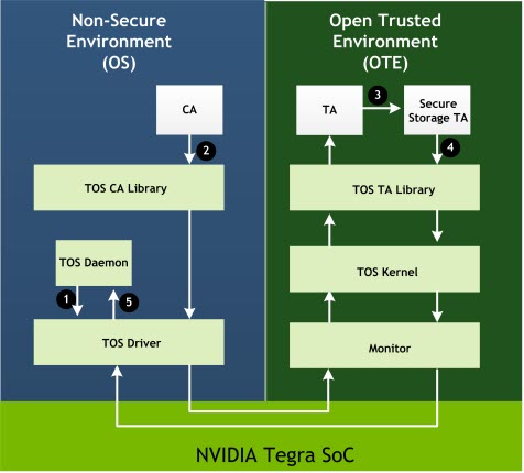
The numbered interactions, provided in the secure storage flow diagram, are as follows.
Interaction | Description |
1 | The Trusted OS (TOS) daemon is blocked on an IOCTL call waiting to service the next secure storage request. |
2 | A CA makes an smc call into the secure world TA requesting some service. |
3 | Specific TA receives the call from the CA and over the course of its operation, suppose it needs to store any data securely, it calls secure storage TA to write/read/modify data. |
4 | SS TA receives the call, processes the request (encrypt/decrypt and packetize) and forwards the request to the TOS driver in NS world. |
5 | The TOS daemon collects the new request and issues the corresponding file operations and notifies the TOS driver that the request is complete. |
Trusty Secure Storage Flow
The DRIVE AGX platform provides an interface library called ote_storage that exposes the interfaces to communicate with the secure storage service. The interfaces exposed by the library, and documentation for it, are inside ote_storage.h header file. It is part of the include directory in the Foundation package available at:
drive-t186ref-foundation/firmwares/src/trusted_os/ta-dev/
The sample_service2.c source provides an example of how to write a simple trusted application (TA) using the secure storage interfaces. The sample_service2 is invoked by the sample_client1 to store and read back a test string from storage.
NVIDIA® Trusted OS technology uses this top-level secure storage directory:
/data/ss
The Secure Storage TA places files in subdirectories under the top-level secure storage directory. The Secure Storage TA names subdirectories with the UUID of the secure storage client. It also encrypts and stores secure data in files in those subdirectories, where it can be subsequently decrypted and accessed.
A daemon running in non-secure space provides access to trusted OS. The daemon initiates these basic file operations, which the Secure Storage TA fulfills:
• Create/delete
• Open/close
• Read/write
• Getsize
• Seek
• Truncate
Trusty - Secure Counter (Legacy)
The Trusted OS library exposes the Tegra Secure Counter (TSC) service for incorporation into TAs that provide a secure incrementing count. Like Secure Storage, TSC runs as a service in the secure world.
TSC has a 56-bit free-running timestamp counter for the oscillator (osc) clock. The architecture supports TSC continually incrementing at the osc frequency. This cannot be modified by the normal world.
Note: | The counter resets when the platform is rebooted. |
TSC is exposed in:
<top>/drive-t186ref-foundation/firmwares/src/trusted_os/ta-dev/include/lib/ote/service/ote_tsc.h
For detailed information on the API, see Secure Counter Services in Trusted OS APIs. This information is provided only in the API Reference for NVIDIA DRIVE OS 5.1 PDK.
Secure Counter Sample
Service1 shows how to call the TSC service to get the counter value using these TSC APIs:
te_error_t ote_tsc_init(void);
te_error_t ote_tsc_deinit(void);
te_error_t ote_tsc_get_msecs(uint64_t *tsc_msecs);
Trusty - Virtualization System Configuration (Legacy)
Important: | Trusty will be removed in future release. Only TZVault shall be supported as the Trusted OS. |
Multiple guest virtual machines may request security services from Trusted OS (TOS). TOS virtualization provides several design features to support this capability:
• Multiple client applications (CAs) running on multiple VMs can communicate with TOS.
• The system can be configured to restrict access to certain trusted applications (TAs) from any VM, using the platform configuration table (PCT).
• Multiple CAs running in the same VM or different VMs can request trusted services from the same trusted application.
• Secure storage is virtualized, and guest VMs can access only their data blobs.
• Each TA manages a guest's context discretely.
By default, all VMs have access to all TAs running in TOS. If TAs are added or removed, the struct in the header file guest_config.h must also be modified.
.tos_cfg = {
.persistent_unique_id = 1,
.num_tos_apps = 7,
.tos_app_uuid[0] = SAMPLE_SERVICE1_UUID,
.tos_app_uuid[1] = SAMPLE_SERVICE2_UUID,
.tos_app_uuid[2] = SERVICE_STORAGE_UUID,
.tos_app_uuid[3] = SERVICE_NVCRYPTO_UUID,
.tos_app_uuid[4] = EFS_CRYPTO_UUID,
.tos_app_uuid[5] = SERVICE_RTC_UUID,
.tos_app_uuid[6] = TESTING_SERVICE_UUID
},
1. Set .num_tos_apps to the number of TAs.
Where n is the number of TAs.
2. Set the elements 0 through n‑1 of .tos_app_uuid to specify the UUID of the TA.
3. After updating guest_config.h, rebuild and re-flash the hypervisor. You need not make any changes on the TOS side to support the new settings.
Trusty - Installing Custom Applications (Legacy)
Before using the sample Client Applications (CAs) and Trusted Applications (TAs), use SDK Manager to install the development tools for your target operating system and the Foundation package. The Foundation package provides the infrastructure to build client and trusted applications using make files.
Consult the SDK Manager documentation for installation requirements and detailed procedures.
Trusted and Client Application Development
The DRIVE AGX platform provides trusted and client applications at:
drive-t186ref-linux/samples/security/ca-dev
drive-t186ref-foundation/firmwares/src/trusted_os/ta-dev
Two trusted application samples perform these functions:
• Crypto operations on sample buffers (AES CBC Encrypt and HMAC-SHA-512 bit)
• Secure Timer reads
• Secure storage interface calls
The sample source files are provided for reference.
To add one or more trusted application to the trusted OS
1. Follow the example in the make file to add a new source and manifest.
2. Examine the make file to:
• Build the source into object files
• Link with libraries
• Make an application
• Concatenate the application binaries into the big tos.img
The tos.img built by the make file is available at:
/drive-t186ref-foundation/firmwares/src/trusted_os/ta-dev/build-ta/t19x/tos.img
3. Flash the newly built tos.img, by replacing it with the one inside drive-t186ref-foundation/firmwares/bin/t19x/tos.img
Consult Flashing Basics for details on flashing the platform.
Building Client Applications on Linux
The process is similar to building trusted applications. The make file for client application is available at:
t186ref-linux/samples/security/ca-dev/build_ca.makefile.mk
The sample shows how to build rich OS applications.
After running the make command, the executables that are built are located at:
drive-t186ref-linux/samples/security/ca-dev/build-ca/
To execute the application to build rich OS
1. Select one of these options:
• Using a USB or SCP, copy the executable to the target device.
• Copy the executable to the target file system on the host machine at:
drive-t186ref-linux/targetfs/usr/local/bin/
2. Reflash the system.
Consult Flashing Basics for details on flashing the platform.
The resulting output of the sample_client1 sample is similar to the following:
root@tegra-ubuntu:/home/nvidia# ./sample_client1
Calling sample_service1
test_ss1 initializing: value_a = 0x55555555, value_b = 0x88888888
test_ss1: Calling te_open_session to increment values a,b
value_a = 0x55555556, value_b = 0x88888889
SS1: Perform CBC Encrypt
[92479.565453] trusty: log overflow.o/p data len = 32
data : e7 66 4c 13 ff 28 c9 65 b0 d2 a0 e7 ec 35 37 6 a5 31 63 63 0 ce dc fa 4e 95 f3 a2 b5 a 56 ed
SS1: Perform SHA-HMAC 512
o/p data len = 64
data : 16 4b 7a 7b fc f8 19 e2 e3 95 fb e7 3b 56 e0 a3 87 bd 64 22 2e 83 1f d6 10 27 c d7 ea 25 5 54 97 58 bf 75 c0 5a 99 4a 6d 3 4f 65 f8 f0 e6 fd
SS1 tests SUCCESSFUL
Calling sample_service2: Secure storage Test
test_ss2 initializing: value_a = 0x33333333, value_b = 0x99999999
test_ss2: Calling te_open_session to increment values a,b
value_a = 0x33333334, value_b = 0x9999999a
te_launch_operation SS2: secure storage buffer size = 43
buffer: Hello, Hello, from secure storage demo app.
SS2 tests SUCCESSFUL
Calling EFS TA
Computing HMAC-SHA 256 of a test i/p buffer:[92479.777010] trusty: log overflow. <This is a test buffer>
HMAC signature computed suffessfully!
o/p data len = 32
data : a3 61 f2 1d e 34 4c 34 d8 39 55 b2 b 7c cc b8 62 e0 1f 49 60 13 e2 29 d1 8 21 13 3f c4 3f bc
Computing RSA-2K of a test i/p buffer: [0,1,2,3,....,255]
o/p data len = 256
data : 4c ab fb 20 e2 1e fd 3d 94 4b c8 2c 20 7c eb 14 a4 54 1b 25 56 37 42 f6 aa cd db cc 63 1c 69 81 97 5a 69 cb ae 45 45 c7 79 9f a3 17 6a 91 15
EFS crypto tests SUCCESSFUL
Building Client Applications on QNX
These instructions build and run the sample application on the development platform. To build a different client, modify the pathnames as appropriate.
To build or add client applications on QNX
1. Locate and edit the following file:
<top>/drive-t186ref-qnx/make/nvdefs.mk
In nvdefs.mk, set the QNX_BASE variable to point to the operating system toolchain base directory containing host/qnx/x86/usr/bin on the host.
Execute these commands to trigger the build:
cd <top>/drive-t186ref-qnx/tos/app/ote/client/sample_client1
make
To run client application on QNX
1. Boot the QNX operating system.
Ensure the trusted OS TEE driver is running.
Run the resource manager, in the background, with these commands:
on -u <driver_uid>:<driver_gid> -A nonroot,allow,mem_peer -A nonroot,allow,pathspace -A nonroot,allow,public_channel -A nonroot,allow,mem_phys -A nonroot,allow,io ./devc-nvtipc &
Run the sample_client1 with the ss1 option using this command:
sample_client1 -t ss1
Upon successful execution, the resulting output is similar to the following:
# sample_client1 -t ss1
Starting tests in a loop. Interation 1
Calling sample_service1
test_ss1 initializing: value_a = 0x55555555, value_b = 0x88888888
test_ss1: Calling te_open_session to increment values a,b
value_a = 0x55555556, value_b = 0x88888889
SS1: Perform CBC Encrypt
o/p data len = 32
data : e7 66 4c 13 ff 28 c9 65 b0 d2 a0 e7 ec 35 37 6 a5 31 63 63 0 ce dc fa 4e 95 f3 a2 b5 a 56 ed
SS1: Perform SHA-HMAC 512
o/p data len = 64
data : 16 4b 7a 7b fc f8 19 e2 e3 95 fb e7 3b 56 e0 a3 87 bd 64 22 2e 83 1f d6 10 27 c d7 ea 25 5 54 97 58 bf 75 c0 5a 99 4a 6d 3 4f 65
f8 f0 e6 fd ca ea b1 a3 4d 4a 6b 4b 63 6e 7 a 38 bc e7 37
SS1 tests SUCCESSFUL
To validate secure storage on QNX
1. Run the resource manager, in the background, with these commands:
on -u <driver_uid>:<driver_gid> -A nonroot,allow,mem_peer -A nonroot,allow,pathspace -A nonroot,allow,public_channel -A nonroot,allow,mem_phys -A nonroot,allow,io ./devc-nvtipc &
2. Run the secure storage daemon, in the background, with the commands:
./nvstoragedaemon -d /dev/trusty-ipc-dev0 -p <mounted_path> -r <mounted_path>/rpmb.dev &
3. Run the sample_client1 with the ss2 option as follows:
sample_client1 -t ss2
Upon successful execution, the resulting output is similar to the following:
# sample_client1 -t ss2
Starting tests in a loop. Interation 1
Calling sample_service2: Secure storage Test
test_ss2 initializing: value_a = 0x33333333, value_b = 0x99999999
test_ss2: Calling te_open_session to increment values a,b
value_a = 0x33333334, value_b = 0x9999999a
te_launch_operation SS2: secure storage buffer size = 43
buffer: Hello, Hello, from secure storage demo app.
SS2 tests SUCCESSFUL
Note: | Secure storage (QNX) uses soft RPMB and does NOT work on fused boards. |
Global Platform API Interface
Both versions of NVIDIA Trusted OS, TZVault and Trusty, support the Global Platform API (GP API) as their primary application interface as defined by the GlobalPlatform TEE communication standard.
GP APIs are supported natively on TZVault and as a wrapper on the legacy Trusty version of NVIDIA Trusted OS. The GlobalPlatform API wrapper libraries support limited functionality. Refer to the “Trusted Execution Environment” section of the API Reference for detailed information on these APIs
Note: | Security Info: To mitigate against cache-based attacks, sensitive key material should not be stored in plain text in a TA's address space. For this reason, the TEE_Malloc API now supports allocating small buffers from non-cache-able device (nGRnE) memory. This option must be used for secret key material only. Refer to the NVIDIA DRIVE OS Linux API reference for more details on how to use this functionality |
Header files
The GlobalPlatform API header files are available at:
<top>/drive-t186ref-foundation/security/trusted-os/trusted-apps/include/lib/
Important: | Trusty will be removed in future release. Only TZVault shall be supported as the Trusted OS. |
Usage and Examples
The NVIDIA Foundation Services provide two sample applications that illustrate usage of the GP API wrapper.
sample_client1_gp.c demonstrates usage of the GP API in a Client Application (CA). Refer to inline documentation in the source file for more verbose instructions about how to use these APIs.
• sample_service3_gp.c demonstrates usage of the GP API in a Trusted Application (TA). Refer to inline documentation in the source files for more verbose instructions about how to use these APIs.
Information about the GlobalPlatform APIs
The home page for the GlobalPlatform API specifications is at:
The GlobalPlatform API wrapper implements the TEE Client API Specification and parts of the TEE Internal API Specification. Both are available through the GlobalPlatform specification page at:
DRIVE Guest OS Security Configurations
This chapter describes system level security features enabled in the DRIVE OS Guest Operating System.
Read-Only Root File System
The root file system resides within the Guest OS and serves as an immutable Root of Trust (RoT) for OS initialization and trusted run-time services. In production systems it is mounted as a read-only partition and the virtual storage device containing the root file system is also made read-only from the Guest OS so that applications running on the Guest OS cannot do block-level writes on the virtual device.
In the default configuration, /dev/vblk_mnand0 contains the root file system and it is mounted at ‘/’ as read-only.
The Guest OS may utilize /dev/vblk_mmand1 as a read-write partition for storing user applications and files in the default configuration.
Mounting the Root File System as Read-Write for Development
To make the root file system read-write for development:
1. Mark the virtual device containing root file system as read-write.
In drive-t186ref-qnx/bsp/device-tree/qnx-device-tree/tegra194-drive-common-qnx-vm1-qnxwrap.dtsi, remove the read-only property from the tegra_virt_storage1 node and then rebuild the device-tree.
2. Mount the root file system as read-write.
Update drive-t186ref-qnx/nvidia-bsp/aarch64le/sbin/startup.sh and modify the automount command to automount -w. Rebuild the IFS and then reflash the system.
Discretionary Access Control
It is desirable to control which processes can talk to the Resource Managers (resmgrs) to avail its services so that access to resmgr services can be restricted. Also, if some process on the system gets compromised, it is desirable to contain its impact by restricting the number of services it can access. This can be achieved by enabling discretionary access control on the device nodes registered by the resmgrs.
On QNX, applications need to call read()/write()/devctl() functions to use the services provided by a resource manager. DRIVE OS drivers enable discretionary access control by controlling which processes can call open() on their device nodes. If a process does not have permission to call open(), its request will fail and it will not be able to make any calls to use the resource manager services. Resource managers assign a Group ID (GID) to their device nodes and only processes that are part of this GID can successfully call open() on the device node. The GID allowed by the device node can be found either by doing ls -l on the device node or via the driver entry in /etc/group. For a client application to be a part of a group, it can use the on utility as shown below, or call the setgroups() system call.
# on -u uid:gid,sgid1,sgid2,sgid3,... <app_command_line>
Where sgid1, sgid2, and sgid3 are the groups the process is part of.
Detailed Sequence of Execution for Each resmgr
For each resmgr that has a resource it wishes to protect:
1. Reserve new unique GIDs for each resmgr in drive-t186ref-qnx/nvidia-bsp/aarch64le/sbin/passwd_file. This file is packaged in the IFS as /etc/group.
For example: nvsku → GID 3000 → string “nvsku”
2. Mark the resource as accessible to members of that group.
A. In resmgr, modify the call to iofunc_attr_init() to set permissions on the object correctly.
/* initialize attribute structure used by the device*/ iofunc_attr_init(&ioFuncAttr, S_IFNAM | S_IRUSR | S_IWUSR | S_IRGRP | S_IWGRP, NULL, NULL);
/* Ensure that device node is configured with correct UID and GID */
ioFuncAttr.uid = UID; /* Processes with the same UID can open the devnode */
ioFuncAttr.gid = GID; /* Processes with the same GID or SGID can open the devnode */
B. If the resmgr registers its own open() callback, call iofunc_open_default from the open() callback. If the resmgr does not register an open() callback, iofunc_open_default is called by default.
C. Verify the device node has the correct permissions:
# ls -l /dev/nvsku
/dev/nvsku -rw-rw---- nvsku : nvsku
For each client of the resmgr:
Launch with relevant supplementary GID (SGID) to access resource. For example, use on -u in startup.sh to include nvsku SGID.
# on -u client_UID:client_GID,3000,other_resmgr_gid <binary>
(where 3000 is the GID that is allowed by nvsku)
Explicit File Permissions and Ownership in IFS
DRIVE OS QNX, by default, defines permissions and ownership of each file in the IFS explicitly. This is done for three reasons:
• Setting ownership of the files implements access control on the files such that only the processes with appropriate privileges are able to access the files.
• Setting permissions on the files explicitly defines which files are read-only, writable, and executable. Therefore, it prevents files from getting corrupted or used in an undesired way.
• To ensure that the files in the IFS image do not pick up permissions of the host files where the image was generated.
The permissions and ownership of the files are set using the following guidelines:
Executable Programs
Case | Perms | UID | GID | Example |
Program is not dropping root privileges | 0500 | 0 | 0 | [uid=0 gid=0 perms=0500] test_app |
Program drops root privileges | 0500 | <APP_UID> | 0 | [uid=2000 gid=0 perms=0500] test_app (where 2000 is the UID of test_app) |
Shared Libraries
Case | Perms | UID | GID | Example |
Shared lib is used by only processes having the same UID | 0500 | <APP_UID> | 0 | [uid=2000 gid=0 perms=0500] libshared.so (where 2000 is the UID of processes using the shared lib) |
Shared lib is used by processes having different UID and GID and the library opens to one resmgr device node | 0550 | 0 | <RESMGR_GID> | [uid=0 gid=2000 perms=0550] libshared.so (where 2000 is the GID that is allowed to open resmgr device node) |
Shared lib is used by processes having different UID and GID and the library does not open a resmgr device node | 0555 | 0 | 0 | [uid=0 gid=0 perms=0555] libshared.so (where libshared.so does not open a resmgr device node) |
Text files:
• Have the same rules as shared libs when it comes to who can access the file.
• Ensure that the files do not have EXEC permissions, and set READ and WRITE permissions appropriately.
Note: | All files in the rootfs are currently configured to have uid=0, gid=0, and perms=0555. You can define your own rootfs that sets more restrictive permissions and ownership by configuring the build file used for the rootfs. |
For more information, see Discretionary Access Control.
Least Privilege Execution
DRIVE OS resmgrs and daemons (i.e., processes that stay alive for a significant amount of time) drop root privileges and operate in least privilege mode by only reserving the privileges required for the driver to function.
All processes started from the default shell start with root privileges and must ensure that they drop unneeded privileges. A root process can do what it wishes in a given VM, such as map MMIOs, kill other services, cause a system crash, and potentially even write the kernel memory.
The issue with running every process as root is that if a process gets compromised, the attacker has access to root privileges and can extract secrets from the system. So use the minimum privileges required for every process. A process that does not have a lot of privileges makes it less attractive for an attacker and even if it gets compromised, the attacker can do very little with it.
The following links provide information about execution with minimum privileges and explain the privileges in a QNX system:
The preferred approach in DRIVE OS to drop root privileges is to start processes with reduced privileges using the on utility. Start a process with a non-root User ID (UID) and Group ID (GID) using on and request the privileges required for initialization using on. Once the process starts, drop the unneeded privileges using procmgr_ability() as early as possible after the process initialization is done.
It is also preferred that each process in DRIVE OS has a unique UID and GID, unless processes are of the same type. For example, all I2C drivers have the same UID and GID. This is a recommendation and you are able to change the UID and GID of the processes. By default, DRIVE OS assigns the same UID and GID to the processes. Again, this is not mandatory, and you can change this scheme.
NVIDIA recommends adding every UID and GID that is used into drive-t186ref-qnx/nvidia-bsp/aarch64le/sbin/passwd_file. This file is packaged in the IFS as /etc/passwd.
Verifying Non-Root Execution
Confirm that the process does not have a UID or GID of 0. For example:
# pidin -F "%U %V %n" -p io-nvgpio
uid gid name
2100 2100 proc/boot/io-nvgpio
Root File System Configuration Location
DRIVE OS QNX stores all the root file system (rootfs) configuration settings within the QNX image file system or device tree.
Since QNX image file system and device tree are part of the secure boot chain, the configuration settings of the rootfs are secure.
The following are the configuration settings for the root file system, their location, and how they are enforced in the default NVIDIA DRIVE AV PCT configuration.
1. Rootfs device node
• Configuration location: The boot_args property in chosen node in the device tree. The string root= in boot_args specifies the device tree. The format of root= string is root=/dev/vblk_mnand0, where /dev/vblk_mnand0 is the device containing the rootfs.
• Configuration enforcement: The device tree property is read by the automount utility, which is started from the startup script. The startup script is packaged in the IFS.
2. Rootfs mount point
• Configuration location: The automount utility hardcodes the default mount point of rootfs as /. The system integrator can override it by passing the -p option.
• Configuration enforcement: The current default is to not pass the -p option. automount is started from the startup script and the startup script is packaged in the IFS.
Even if the option was passed, it would be passed in the startup script.
3. Rootfs mount type
• Configuration location: rootfs is always assumed to be of qnx6 type in the automount tool.
• Configuration enforcement: The automount utility is started from the startup script. The startup script is packaged in the IFS.
4. Rootfs mount permissions and ownership
• Configuration location: rootfs permissions and ownership are configured internally by the automount utility and there is no control for the user. The current defaults are:
• Read-only mount point.
• The directories are searchable by every user and group.
• The individual file permissions are enforced by the build file used to build the rootfs.
• Configuration enforcement: The automount utility is started from the startup script. The startup script is packaged in the IFS.
Startup Script Location
All scripts loaded during the OS boot are located in the primary image file system (IFS). QNX IFS is part of the secure boot chain. Hence, putting the startup scripts in the IFS makes it difficult for an attacker to start malicious processes during boot.
Startup Executable Locations
On a DRIVE QNX system, file system integrity is provided for the IFS, secondary IFS, and the root file system.
Hence, in the default DRIVE QNX setup, all program executables and libraries required during QNX startup are loaded either from the IFS, secondary IFS, or the root file system to reduce the risk of spoofing attacks and undesired processes being loaded during boot.
Secure Debug Utilities
The following section describes how to enable JTAG support on secure targets.
Enabling JTAG Support on Secure Targets
On secure targets, where the ODM production fuse has been blown, BootROM locks the JTAG connection interface. To enable the JTAG interface on such a target, a special BCT is required where certain parameters are set.
To enable the JTAG interface on a secure target
1. Set the desired debugging features through the BCT section of the flashing configuration file.
2. Generate a new BCT image.
To enable debugging features through the BCT configuration file
1. In the BCT partition of the flashing configuration file, set the uid attribute to the UID of the target device.
Set the sec_dbg_ctrl attribute to specify the debugging features desired.
The sec_dbg_ctrl attribute collection of bit fields are as follows.
Bits | Feature enabled by a ‘1’ bit |
31 | Ramdump |
30:11 | Reserved |
10 | SCE secure debug |
9 | SPE secure debug |
8 | BPMP secure debug |
7:6 | Reserved |
5 | DBGEN |
4 | NIDEN |
3 | SPIDEN |
2 | SPNIDEN |
1 | DEVICEEN |
0 | JTAG_ENABLE (must be 1 to enable the JTAG interface) |
On secure targets BootROM compares the UID of the chip to the UID in the BCT, and enables debug features for bits 0, 1, 2, 3, 5 and 31 if the UIDs match.
An example of a flashing configuration file, that specifies the UID value for a specific target device, to enable the JTAG interface with all features except Ramdump, is as follows:
[partition]
name=bct
allocation_policy=sequential
filesystem_type=basic
uid=0xa18010016419f105000000000a010380
sec_dbg_ctrl=0x73F
size=0x80000
partition_attribute=0
To update the BCT and bootloader images
1. Enable any required debugging features through the configuration file.
2. Navigate to the flashing scripts directory:
cd drive-t186ref-foundation/tools/host/flashtools/bootburn_t19x
3. Create offline images that incorporate your changes using create_bsp_image.sh.
4. Update the newly generated BCT and bootloader images, MB1 and MB1 recovery, by either of these methods:
• Use the Update Tool to compile update_sample and copy it to the target.
• Flash the complete images by running flash_bsp_images.sh.