Debugging NvMedia CSI Capture Errors
Note: | All the commands in this chapter must be run as root user (with sudo). |
The terms used throughout this document are as follows:
• CCPLEX: Carmel CPU complex running the capture stack and applications.
• CRC: Cyclic Redundancy Check, a 16-bit checksum present in MIPI CSI packet footer.
• ECC: Error Correction Code, a 6-bit code present in MIPI CSI packet header that can be used by the receiver to correct single bit errors and detect double bit errors.
• NVCSI: An SoC MIPI CSI interface conformant to CSI2 v2.0 specification.
• RCE: Realtime Camera Engine is an ARM Cortex R5 core running an RTOS that handles programming of NVCSI/VI engines and notify messages from VI.
• VI: An SoC Video Input module that takes frame data from NVCSI interface and writes it to memory.
This document describes:
• The various approaches to debug CSI capture errors on Xavier-based platforms.
• How to identify which approach to use for debugging.
• How the errors can be identified.
• Probable root causes for the errors.
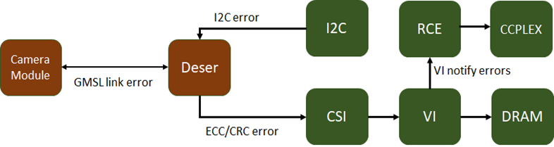
The layers at which errors can occur during a camera capture are as follows:
NvMedia Error Logs
When an error is encountered in decoding CSI packets received at an SoC CSI interface and writing the raw frame data to memory, the VI hardware engine notifies these errors to RCE. The capture stack running on CCPLEX queries the capture status from RCE and displays:
• The CSI stream ID (CSI brick).
• VC ID for which the error occurred.
• The type of error.
• Detailed errors per the error type.
The error status provides a good starting point to determine the root cause and identify the next steps.
If the VI engine did not successfully capture a frame, and did not encounter and report an error to RCE, then the error message below or a similar one will be displayed:
Frame Start Timeout Error
EngineStatusError (2), Detailed Error Code: 00000001 at StreamId:0 vcId:0 CSIFrameId:0 notified-bits:2000000or
Frame End Timeout Error
EngineStatusError (2), Detailed Error Code: 00000002 at StreamId:0 vcId:0 CSIFrameId:0 notified-bits:4000000
This can be due to one of two reasons:
1. The deserializer is not streaming data.
2. The VI channel is not configured to capture the correct data type/VC id.
The remainder of this document describes the root causes for these errors.
RCE Traces
Apart from the error events, the VI notifies several other events to RCE that can be read by CCPLEX using the RCE tracing framework. This notification is disabled by default and can be enabled as follows:
1. Run these commands to enable the RCE traces before starting capture:
echo 10000 > /sys/kernel/debug/tracing/buffer_size_kb
echo 1 > /sys/kernel/debug/tracing/tracing_on
echo 1 > /sys/kernel/debug/tracing/events/tegra_rtcpu/enable
echo 3 > /sys/kernel/debug/camrtc/log-level
2. After starting capture, read the RCE traces using:
cat /sys/kernel/debug/tracing/trace
3. Clear the RCE trace from the previous capture using:
echo > /sys/kernel/debug/tracing/trace
The RCE trace logs several events such as SOF, EOF that can be used to determine if the VI channel is capturing data or not. Capture the RCE traces and provide them to NVIDIA for further analysis.
Reading CSI/VI Registers
To read CSI/VI registers, the CSI/VI engines must be in a powered-on state. If the engines are not powered on, attempting to access the registers causes a system crash.
In DRIVE OS 5.1.0 and 5.1.3 SDK releases, direct access to forcefully power-on the CSI/VI engines is NOT provided. To ensure CSI/VI remains powered-on, run an error-free camera capture on a CSI brick other than the one used for debugging capture errors.
In DRIVE OS 5.1.6 or later SDK releases, forcefully power-on the CSI/VI engines:
echo on > /sys/devices/platform/host1x/15a00000.nvcsi/power/control
echo on > /sys/devices/platform/host1x/15c10000.vi/power/control
echo 1 > /sys/devices/platform/host1x/15a00000.nvcsi/acm/force_on
echo 1 > /sys/devices/platform/host1x/15c10000.vi/acm/force_on
Once the CSI/VI engines are powered on, read the registers using the devmem2 tool packaged with the DRIVE OS SDK:
./devmem2 <register_addr>
Where <register_addr> is the address of the register for the CSI/VI engine.
VI Frame Count
Each VI channel has a FRAME_COUNT register that records the number of FS and FE seen by the VI channel. The absolute address of FRAME_COUNT register is:
0x15f11070 + <vi_channel_no> * 0x400
Note: | The vi_channel_no starts from 35 downwards for RGB, RAW, and YUV packed formats, and from 0 upwards for YUV planar and semiplanar formats. |
Read the register value using the devmem2 tool packaged with the SDK.
./devmem2 <register_addr>
Interpret the register value read by devmem2:
Bit | Reset Value | Description |
31:24 | X | BAD: Count of faulty frame end seen, saturates at 255. |
23:12 | X | FE: Count of all frame end seen, saturates at 4095. |
11:0 | X | FS: Count of all frame start seen, saturates at 4095. |
CSI Debug Counters
If the VI frame count register indicates that VI is not seeing any FS/FE packets, the next step is to determine if the NVCSI engine has encountered any FS/FE packets. For example, whether the FS/FE packets were received from the deserializer.
Xavier NVCSI provides six (6) debug counter registers that can count several different events seen on the NVCSI interface. Correspondingly, there are six (6) debug control registers that can be used to program the CSI stream ID and the event to be counted for each debug counter.
The debug control registers are located at address:
0x15a00084 + <i>*0x4
The debug counter registers are located at:
0x15a0009c + <i>* 0x4
Where <i> is in the range [0,5].
The bit fields of the debug control register are as follows:
Bit | Reset Value | Description |
15:8 | 0x0 | debug_1_event_sel: Value ranges from 0 to 148, Selects the corresponding |
2:0 | NO_STREAM | debug_1_stream_sel: 0x1 to 0x6 = Selects Stream 0 to Stream 5 0 = NO_STREAM 1 = STREAM_0 2 = STREAM_1 3 = STREAM_2 4 = STREAM_3 5 = STREAM_4 6 = STREAM_5 |
To program the debug counters to start counting events:
1. Write 0x1 to the debug counter register to clear the previous count.
2. Write the corresponding debug control register to select the stream for this counter and the event to be counted.
The debug counter event mapping:
Event Index | Event |
0 | VC0 ppfsm timeout |
1 | VC0 PH ecc single bit error |
2 | VC0 payload CRC error |
3 | VC0 line short error |
4 | VC0 one of the two packet header CRC error for CPHY case |
5 | VC0 EOL number |
6 | VC0 SOL number |
7 | VC0 EOF number |
8 | VC0 SOF number |
9-17 | The same mapping for VC1 |
18-26 | The same mapping for VC2 |
27-35 | The same mapping for VC3 |
36-44 | The same mapping for VC4 |
45-53 | The same mapping for VC5 |
54-62 | The same mapping for VC6 |
63-71 | The same mapping for VC7 |
72-80 | The same mapping for VC8 |
81-89 | The same mapping for VC9 |
90-98 | The same mapping for VC10 |
99-107 | The same mapping for VC11 |
108-116 | The same mapping for VC12 |
117-125 | The same mapping for VC13 |
126-134 | The same mapping for VC14 |
135-143 | The same mapping for VC15 |
144 | Multi bit ECC error in the packet header |
145 | Both the two packet headers CRC error for CPHY case |
146 | EOT number |
147 | PH number (note that for CPHY, every PH will count here) |
148 | Data number from CIL to PP (unit is 8 bytes) |
VI Channel Registers
Some errors such as short/long line, short frame, and pixel runaway may point to errors in the VI channel configuration.
VI_CH0_MATCH_0
Addr: 0x15f1101c
The table below contains the CSI stream ID and VC ID that this VI channel is programmed to capture:
Bit | Reset Value | Description |
19:14 | 0x0 | STREAM |
13:8 | 0x3f | STREAM_MASK |
7:4 | 0x0 | VIRTUAL_CHANNEL |
3:0 | 0xf | VIRTUAL_CHANNEL_MASK |
The STREAM and VIRTUAL_CHANNEL are one-hot encoded. For example, for virtual channel 0 on stream 2:
STREAM = 6b000100 or 0x4
VIRTUAL_CHANNEL = 4b0001 or 0x1
VI_CH0_MATCH_DATATYPE_0
Addr: 0x15f11028
The table below contains the CSI data type expected by this VI channel:
Bit | Reset Value | Description |
11:6 | 0x0 | DATATYPE |
5:0 | 0x3f | DATATYPE_MASK |
VI_CH0_FRAME_X_0 and VI_CH0_FRAME_Y_0
Addr: 0x15f11034 and 0x15f11038
The frame X and Y dimensions:
VI_CH0_DT_OVERRIDE_0
Addr: 0x15f11030
Bit | Reset Value | Description |
6:1 | 0x2e | OVRD_DT: Datatype to override input format with. |
0 | 0x0 | DT_OVRD_EN: Enable input format override 0 = DISABLE 1 = ENABLE |
When CSI data from the sensor has one of the “user defined” byte-based data types defined by MIPI CSI2 specification, it must be overridden to a well-defined data type, such as RAW8, for VI to be able to write the frame to memory. In this case, the MATCH_DATATYPE must contain the user defined data type present in sensor data, DT_OVRD_EN must be 1, and OVRD_DT must be set to the well-defined data type used for overriding.