Using the Bootloader Recovery Mechanism
The bootloader includes:
• BootROM
• Microboot 1 (MB1)
• Microboot 2 (MB2)
• Quickboot (QB)
• Hypervisor which includes:
• Partition Loader (PL)
• Operating System Loader (OSL)
These components load additional firmware components including:
• Boot images
• Partition images
• Other firmware
The bootloader fails to load if:
• Image corruption is declared: during boot, hash validation and signature authentication is performed. If the validation or authentication fails, the system declares that the image is corrupt.
• Device read failure occurs: during boot, if hardware issues are detected, the system returns a device read error.
These failures result in a boot process failure and therefore require using the provided bootloader recovery mechanism.
During the boot process, the bootloader recovery mechanism ensures a functioning firmware is loaded.
To ensure the recovery mechanism functions flawlessly, be aware of:
• Firmware components have dependencies on each other.
For example, the BPMP firmware and kernel are dependent on each other. If the BPMP firmware version and the kernel version are functionally incompatible, the system functioning may be abnormal and operation may not be as expected.
• Firmware updating process failures.
For example, if a power outage occurs while the firmware is being updated the BPMP firmware may be updated with the latest version while the kernel retains the outdated version. Due to this version mismatch, the system malfunctions and operation may not be as expected.
Therefore, redundant copies are a set of all the firmware components that are functionally compatible with each other. This set of firmware components is called Boot Chain.
• The primary firmware components are on one boot chain.
• Redundant firmware components are on another boot chain.
Recovery Mechanism Boot Chains
The recovery mechanism maintains two boot chains:
• Boot Chain A
• Boot Chain B
One bootchain is active at any given time.
• The active boot chain is referred to as: Active Boot Chain.
• The inactive boot chain is referred to as: Inactive Boot Chain.
Boot Chain Process
During normal operation, the booloaders load the firmware components in the Active Boot Chain. If the system cannot boot the Active Boot Chain, the system resets to boot the other boot chain.
• The BootROM, as a root of the boot chain, selects an initial Active Boot Chain.
• Every bootloader must load firmware components from the Active Boot Chain.
• If a bootloader fails to load a firmware component, the system switches to the Active Boot Chain and the Inactive Boot Chain is reset.
Advantages
The boot chaining process provides these advantages:
• Handles cases of partial update so that the system is always bootable.
• Except for a ratchet update case, each chain can be updated independently.
• Compatibility issues between firmware components is eliminated.
Side Effects
The side effects of the boot chaining process include:
• Only two corrupted firmware components can cause an unusable system.
For example, if the BPMP firmware in the Active Boot Chain is corrupted, and the kernel image in the Inactive Boot Chain is corrupted, the system is unable to boot any of the boot chains and cannot ever boot.
Components Outside the Boot Chain
Some firmware components are NOT included in any boot chain because of the nature of the components or due to BootROM limitation. For these components, multiple copies exist in the system. The boot loader locates the valid component from among the multiple copies.
• The BootROM BCT selects the Active Boot Chain.
• The Global Partition Table defines the images that belong to each boot chain.
Consequently, these components cannot belong to the boot chain.
Boot Recovery Mechanism Flow
Boot recovery implementation is as follows:
The data types used for the recovery mechanism include:
• Scratch register
• BootROM BCT
• Soft fuses
Scratch Register
The PMC scratch register, SCRATCH_99, also referred to as SCRATCHr, holds the Active Boot Chain and the Invalid Chain field.
The register bit definition is as follows:
Bit | Default | Setting | Description |
31:2 | 0 | RSVD | Do NOT modify this value. It is reserved. |
1 | 0 | INVALID_CHAIN | Identifies the corrupted Inactive Boot Chain. The status is as follows: • When set to one, inactive chain is corrupted. • When cleared to 0, no corrupted chain is detected. |
0 | X | ACTIVE_BOOT_CHAIN | When cleared to 0, the Active Boot Chain is set to 0, or Boot Chain A. When set to 1, the Active Boot Chain is set to 1, or Boot Chain B. |
The contents of the scratch register are retained across soft reboots.
The scratch register is written when:
• User wishes to boot a particular boot chain and the user writes the boot chain in the scratch register then issues a system reboot.
• A bootloader detects corruption and the user updates the INVALID_CHAIN register bit and then sets a new Active Boot Chain.
• Upon a normal cold boot, the BootROM initializes the register with the selected boot chain.
The contents of the scratch register are read when:
• At any stage during boot, a bootloader reads the scratch register to find the Active Boot Chain. Once the firmware determines the Active Boot Chain, it loads the next stage firmware images in the chain.
• Before beginning a system update, the Update tool reads the value to determine whether the system has booted the desired boot chain.
All bootloaders, except the hypervisor, have read and write permissions for the scratch register. Hypervisor access permissions for the scratch register are as follows:
• Read access: The Partition Loader and Operating System Loader of each guest have read access to the scratch register. Additionally, the Monitor server has read access to the scratch register.
• Write access: The Monitor server has write access to the scratch register. The PL, OSL, and Guest OS do NOT have write access.
BootROM BCT
The BootROM BCT includes the following data types to select the primary boot chain:
Data Type | Description |
NonGPIOSelectBootChain | Indicates the primary boot chain when the GPIO selection is NOT enabled. 0 = Boot Chain A 1 = Boot Chain B |
GPIOSelectBootChain | Toggles to enable or disable the GPIO selection of the boot chain. 0 = disable GPIO selection and use the boot chain selected by NonGPIOSelectBootChain. 1= enable GPIO selection and use the boot chain selected by GPIO input. When enabled, GPIOConfigAddressBootChain and GPIOPadctlAddressBootChain values are used to configure GPIO and read input from the GPIO. |
GPIOConfigAddressBootChain | Identifies the GPIO configuration address used to select the boot chain. |
GPIOPadctlAddressBootChain | Identifies the GPIO Pad control address used to select the boot chain. |
For guidance on connecting a GPIO to enable selection of the boot chain, refer to the Xavier Interface Design Guide (DG-08535-001).
Soft Fuse
Soft fuses are used to determine the recovery action to take when a bootloader fails to load a firmware component. The settings include:
Data Type | Description |
SwitchBootChain | If set, switches the boot chain. MB1 overwrites the value to 0 when GPIO selection is enabled. |
ResetToRecovery | Used when the system does not switch the boot chain. When set to 1, the system reboots to forced recovery mode. When cleared to 0, the system hangs. |
Selecting the Active Boot Chain by BootROM
The BootROM, which is the root boot chain, is responsible for selecting the Active Boot Chain after the system powers up. The selection sequence is as follows:
• Read GPIOSelectBootChain and NonGPIOSelectBootChain information from BR BCT.
• If GPIOSelectBootChain is enabled, read the input from the selected GPIO and use the input value as a Boot Chain. A GPIO value of 0 sets Boot Chain A. A GPIO value of 1 sets Boot Chain B as an Active Boot Chain.
• If GPIOSelectBootChain is not enabled and it is a cold boot, BootROM uses NonGPIOSelectBootChain value in BR BCT as an Active Boot Chain. Value 0 sets Boot Chain A and value of 1 sets Boot Chain B as Active Boot Chain.
• If GPIOSelectBootChain is not enabled and it is not a cold boot, BootROM uses the active boot chain defined in the SCRATCHr register.
The flow is as follows:

Selecting the Boot Chain by the Loader
Each bootloader checks the contents of the SCRATCHr register to identify the Active Boot Chain. The bootloader then loads the next stage firmware components in the boot chain.
Triggering the Recovery Mechanism Inside a Guest OS Container
The recovery mechanism discussed under topic Triggering Recovery Mechanism by Loader is true until Hypervisor binary is loaded. Once Hypervisor boots up, it is no longer true due to the following reasons:
• More than one guest OS is configured in the PCT. Each guest OS boots up independently in its guest OS environment provided by Hypervisor. Guest OSes do not have information about other guest OSes.
• It may be possible that one or more guest OS boot fails, and other guest OSes boot up fine. There may be multiple boot failure scenarios here. How is each failure scenario handled?
• If one or more guest OS boot fails, then how and who decides whether to trigger recovery mechanism or reboot that guest OS?
• Triggering recovery mechanism in a guest OS environment involves informing Hypervisor. Hypervisor makes the final decision to trigger recovery.
To handle boot failures inside a guest OS environment, a different recovery mechanism policy is required inside the guest OS environment.
Scratch Registers
SCRATCH_SCRATCH_99: Bit 0 of this scratch register is called corrupt bit. It indicates whether inactive chain is good or corrupted.
• Value of 0 indicates inactive chain is good and 1 indicates inactive chain is corrupt.
Privileged Guest OS
The notion of privileged guest OS means that guest OS is allowed to read and write to the SCRATCH_SCRATCH_99 register. The request to read and write to the scratch register is sent to Hypervisor and Hypervisor in turn reads and writes to the physical scratch register. Privileged guest OS also has the ability to trigger a system reset. Hypervisor receives the system reset request and prepares the system for reboot.
Unprivileged Guest OS
This guest OS is also allowed to read and write to the SCRATCH_SCRATCH_99 register. The request to read and write is sent to Hypervisor and Hypervisor in turn does not read or write to the physical scratch register. Here, Hypervisor emulates the read and write. Unprivileged guest OS can request Hypervisor to perform a system reset but Hypervisor ignores the request and does nothing.
Marking a Guest OS as Privileged Guest OS
You must mark a guest OS as privileged guest OS in the PCT before flashing the system. Inside the PCT folder, in the guest_config.h file, set the system_reset attribute for a particular guest OS to mark it as privileged guest OS.
Assumptions
• There must only be one privileged guest OS in the system.
• System is booted using BR-BCT based boot chain selection mechanism. Recovery mechanism inside the guest OS environment does not work for GPIO based boot chain selection mechanism.
Triggering the Recovery Mechanism by BootROM
The BootROM loads MB1 from the Active Boot Chain.
• If BootROM fails to load the MB1 image in the Active Boot Chain, the sequence is as follows:
• Toggle the Active Boot Chain and set the invalid boot chain to 1.
• Load MB1 from the new Active Boot Chain.
• If a failure occurs again, boot into forced recovery mode.
• Soft fuse values are NOT used by BootROM.
Because BR BCT does NOT belong to any boot chain, recovery for this component takes place as follows:
• A single partition is provided for storing BR BCT.
• The partition is shared by both boot chains. The partition contains multiple copies of BR BCT. All copies are identical.
• Each copy is placed at the beginning of the boot storage device.
• The BootROM handles the recovery of BR BCT. If one copy of BR BCT is found to be corrupted, the BootROM proceeds with the next copy of the BR BCT until a valid copy is located. If a valid copy is not located, BootROM resets into forced recovery mode.
• At the time of the system update, each copy of BR BCT is updated to the new version to ensure all copies are at the same version.
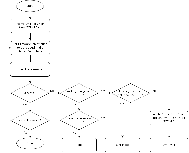
Triggering Recovery Mechanism by Loader
During boot, when any bootloader, except BootROM, fails to load the next stage firmware, the recovery mechanism is triggered as follows:
• Attempts to load the next stage firmware in the Active Boot Chain.
• If the next stage firmware is loaded successfully, the loader continues to boot.
• If the next stage firmware is NOT successfully loaded, the recovery mechanism is triggered.
• If the INVALID_CHAIN bit in the SCRATCHr register is set to 1 or the switch_boot_chain soft fuse value is cleared to 0, these recovery actions are performed:
• If the reset_to_recovery soft fuse value is set to 1, the system goes into forced recovery mode.
• If the reset_to_recovery soft fuse value is cleared to 0, the system hangs.
• If the INVALID_CHAIN bit is NOT set, and the switch_boot_chain soft fuse value is set to 1, then set the INVALID_CHAIN bit to 1 and toggle the ACTIVE_BOOT_CHAIN bit in the SCRATCHr register and issue a reboot so that the system boots a different boot chain.
The flow for triggering the recovery mechanism by the loader is as follows:
MB2 and Quickboot load the Global Partition Table. Because this firmware component does not belong to any boot chain, the recovery flow is as follows:
• There is a single partition to store the global partition table of the system.
• The single partition contains multiple signed copies of the partition table. If one copy is corrupted, the system uses the next copy.
• The global partition table contains information for both boot chains of the system. As a result, the global partition table must NOT be erased during the update. If the global partition table is erased, the system cannot be recovered without reflashing the entire images.
Partition Layout
The partition layout on flash is organized to support the recovery mechanism as follows:
• For each partition, other than BR BCT and Global Partition Table, there are two partitions: Boot Chain A and Boot Chain B.
• For BR BCT, there is single common partition. This partition contains multiple copies of BR BCT residing at the beginning boot storage device.
• For global partition table, there is single partition containing multiple copies of the partition table.