Image Camera Capture (nvmimg_cap)
The NvMedia Image Camera Capture sample application nvmimg_cap demonstrates how to use the NvMedia Image Sensor Control API to capture frames from the sensors and display them to a screen or save them to a file.
The nvmimg_cap sample application captures frames from sensors using the NvMedia Image Sensor Control API to display them to a screen and/or save them to a file. It can also be used to test the error detection functionality of the ISC.
The application requires you to provide command line input as well as a group of settings as defined in the configuration file.
The configuration file contains two sets of information.
• I2C bus and the device address to program sensor, serializer and the aggregator camera module
• CSI capture configurations used to program the Tegra CSI and Video Input (VI) modules
The CSI packets from the aggregator reach the Video Input (VI) module and saved to memory. The frames can be displayed using the Display Controller (DC) and/or saved to a file.
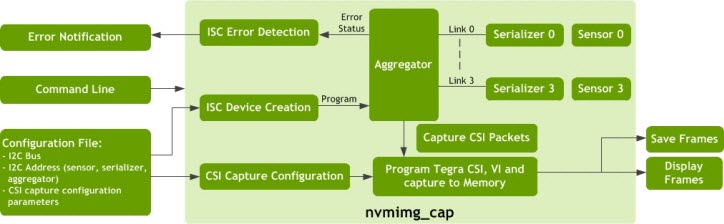
Error Detection
The Image Capture tool can be used to verify the error detection capability of ISC. The aggregator device detects errors such as camera power failure or broken video links during the capture process. The aggregator reports errors using GPIO interrupt to the application.
The application may take any appropriate action, including reading the status register of the aggregator to determine whether the camera, serializer or GMSL link caused the failure. When an error is detected, the user receives a message similar to the following:
nvidia@tegra-ubuntu:~$ ./nvmimg_cap -v 2 -cf ddpx-a.conf -c SF3324-CSI-A
nvmedia: Using params set: SF3324-CSI-A for capture
Sensor AR0231 RCCB Rev7 detected!
Type "h" for a list of options
-nvmedia: _CaptureThreadFunc: VC:0 FPS=0 delta=13758273584
nvmedia: ERROR: ExecuteNextCommand: Failed to read command
-nvmedia: ERROR: _GetError_max96712:GMSL2 Link Unlocked
nvmedia: WARNING: _CaptureThreadFunc: NvMediaICPGetFrameEx timed out
nvmedia: WARNING: _CaptureThreadFunc:
Camera Capture Pipeline
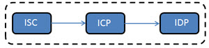
The Camera Capture pipeline consists of three components:
• Image Sensor Control (ISC): Calibrates the camera sensors to provide the images. It is used for controlling the sensor, for example, by setting the exposure and white balance.
The initial configuration of the aggregators, serializers, and sensors are performed by the client application. The client application must:
• Create handles for the root, aggregator, serializer and sensor devices
• Perform the initialization
• Pass these handles to the sensor control component at component creation
• Image Capture Processing (ICP): Captures the frames coming from the CSI interface. It can capture an individual image from a camera, or aggregated images from multiple cameras. The output of this component provides the captured images.
• Image Display Processing (IDP): Displays the YUV and RGB formatted images. It provides mechanisms to render YUV and RGBA surfaces on the display.
The following figure outlines the Camera Capture pipeline.
Code Flow
This is the flow of the code for the camera capture components:
uint32_t addressList[1] = {0};
// Create ISC root device
iscRootDevice = NvMediaISCRootDeviceCreate(
ISC_ROOT_DEVICE_CFG(csiLink, i2cPort));
// Create aggregator device
addressList[0] = aggregatorDeviceAddress;
iscAggregatorDevice = NvMediaISCDeviceCreate(iscRootDevice,
addressList,
1,
GetAggregatorDriver(),
NULL);
// Create serializer devices
for(i = 0; i < TOTAL_DEVICES; i++)
{
addressList[0] = serializerDeviceAddress[i];
iscSerializerDevice[i] = NvMediaISCDeviceCreate(iscRootDevice,
addressList,
1,
GetSerializerDriver(),
NULL);
}
// Create sensor devices
for(i = 0; i < TOTAL_DEVICES; i++)
{
addressList[0] = sensorDeviceAddress[i];
iscSensorDevice[i] = NvMediaISCDeviceCreate(iscRootDevice,
addressList,
1,
GetSensorDriver(),
NULL);
}
// Program ISC Devices
ProgramISCDevices();
// Use ISC devices
...
// When application prepares to quit,
// Destroy sensor and serializer devices
for(i = 0; i < TOTAL_DEVICES; i++) {
if(iscSerializerDevice[i])
NvMediaISCDeviceDestroy(iscSerializerDevice[i]);
if(iscSensorDevice[i])
NvMediaISCDeviceDestroy(iscSensorDevice[i]);
}
// Destroy aggregator
if(iscAggregatorDevice)
NvMediaISCDeviceDestroy(iscAggregatorDevice);
// Destroy ISC root device
if(isc->iscRootDevice)
NvMediaISCRootDeviceDestroy(isc->iscRootDevice);
ICP:
// Create ICP
icpCapture = NvMediaICPCreateEx(NVMEDIA_IMAGE_CAPTURE_INTERFACE_FORMAT_CSI,
ICP_CAPTURE_FRAME_BUFS,
captureSettings);
// Feed frame
NvMediaICPFeedFrame(icpCapture,
captureBuffer->image,
FEED_FRAME_TIMEOUT);
// Loop until exit
while(!quit)
{
// Feed frame
NvMediaICPFeedFrameEx(icpCapture,
captureBuffer->image,
FEED_FRAME_TIMEOUT);
// Get captured frame
capturedFrame = NvMediaICPGetFrameEx(icpCapture,
GET_FRAME_TIMEOUT);
// Put image onto output queue
PutImageOnQueue();
}
// Get extra frame that was fed before the loop and release it
capturedFrame = NvMediaICPGetFrameEx(icpCapture,
GET_FRAME_TIMEOUT);
ReleaseImage(capturedFrame);
// Destroy ICP
NvMediaICPDestroyEx(icpCapture);
IDP:
// Create display
display = NvMediaIDPCreate(displayId,
windowId,
NULL,
isEnabled);
while(!quit)
{
// Get image from output queue
outputImage = GetImageFromQueue();
// Display image
status = NvMediaIDPFlip(display,
outputImage,
srcRect,
dstRect,
releaseList,
timeStamp);
// Release Images from releaseList
while(releaseList) {
ReleaseImage(*releaseList);
releaseList++;
}
}
// Destroy IDP
NvMediaIDPDestroy(display);
Slave Capture
When slave capture is enabled, the slave (processor B) captures the images from the sensors that are already programmed by the master (processor A).
To enable this feature, use the --slave switch when running nvmimg_cap on processor B.
Limitations
• Before starting nvmimg_cap on the slave, you must start capture on the master. The slave can continue to capture even after the master has stopped capturing.
• processors A and B capture only in DPHY 1.2 mode.
Command Line Usage
This section documents how to run the Image Camera Capture sample application on supported platforms.
To run Image Camera Capture sample application on the P3479 board
• Enter this command:
$ ./nvmimg_cap -cf <config filename> -c <config setname> [switches]
Where:
• The ‑cf switch specifies the pathname of a configuration file.
• The ‑c switch specifies the name of a configuration set defined in the configuration file. The configuration set defines a group of capture settings that the program is to use.
• [switches] are zero or more optional command line switches, described in the table below.
To quit the application, enter q at the command line.
Command Line Switches
This table describes the command line switches:
OptionSwitch | Parameter | Description | Default |
--aggregate | [n] | Creates an aggregated image from the captured frame of the size: (W×n)×H. | N/A |
-c | [name] | Specifies the name of the configuration set that the program is to use. | N/A |
-cf | [filename] | Specifies the configuration file. Co-locate the file with nvmimg_cap. | N/A |
-d | [id] | Enables the display. If provided, uses the display with the specified ID. | If the optionswitch is not specified, the display is disabled. If the optionswitch is specified but the ID is not provided, the sample uses the first display available. |
--ext_sync | <n> | Enables external synchronization with a duty ratio of <n>, where 0.0 < <n> < 1.0. | If <n> is out of range, 0.25. If the switch is not specified, value is set by the aggregator. |
-f | <file prefix> | Saves captured frames to a file. Each filename starts with the specified prefix concatenated with any calibration parameters and the frame index. | Frames are not saved to file(s). |
-h | N/A | Prints the usage syntax. | N/A |
-lc | N/A | Lists the available configuration sets. | N/A |
-n | <frames> | Number of frames to capture. The application quits automatically after capturing this many frames. | N/A |
-p | <x:y:w:h> | Specifies the window position rectangle. | No positioning. |
--slave | N/A | Specifies that the application is running with a slave aggregator. For more information, see Slave Capture. | N/A |
--tpg_offset | <n> | TPG channel offset. To be used with T19x (Jetson AGX Xavier) only. In case of capture resources equally divided between guest VMs, sets offset for TPG capture to 0 from VM0 and 8 from VM1. | 0 |
-v | [level] | Logging level. Value may be: • 0: Errors • 1: Warnings • 2: Information • 3: Debug | 0 |
-w | <id> | Uses the window with the specified ID for display. | 0 |
--timestamp | N/A | Prints capture timestamp information. | N/A |
-z | <depth> | Specifies the depth for the display. | 0 |
This table describes the run-time commands:
Command | Description |
h | Prints the available commands. |
q | Quits the application. |
Configuration Sets Defined in the Configuration File
A configuration file contains one or more configuration sets: groups of properties that configure capture settings. The application selects and applies the configuration set specified by the ‑c switch in the command line.
Each configuration set begins with a capture-params-set line which specifies a unique configuration set number, followed by the configuration parameters.
This table describes the configuration parameters:
Parameter | Description | Valid Value/Example |
capture-name | Specifies the configuration set’s name. | Any string. |
capture-description | Describes the type of sensor being used for capture. | Any string. |
input_device | Specifies the name of the capture image device. | "ref_max96712_96705_ar0231", "ref_max96712_96705_ar0144" |
input_format | Specifies the capture format of the sensor. | "422p", "raw12", "raw16log", |
surface_format | Specifies the CSI surface format. | "yv16", "rgb", "raw8", "raw10", "raw12" |
resolution | Specifies the input resolution. | "<width>x<height>" |
csi_lanes | Specifies the CSI interface lanes. | 1, 2, 4 |
interface | Specifies the capture interface. | "csi-a", "csi-b", "csi-c", "csi-d", "csi-e", "csi-f", “csi-g”, “csi-h” "csi-ab", "csi-cd", "csi-ef", "csi-gh", "trio-a", "trio-b", "trio-c", "trio-d", "trio-e", "trio-f", "trio-g", "trio-h", "trio-ab", "trio-cd", "trio-ef", "trio-gh" |
embedded_lines_top | Specifies the number of extra top lines for the CSI capture. | Unsigned integer. Example: 2 |
embedded_lines_bottom | Specifies the number of extra bottom lines for the CSI capture. | Unsigned integer. Example: 2 |
i2c_device | Specifies the I2C device to use for configuring the CSI device. | Example: 0 |
serializer_address | Specifies the address of the serializer device. | Example: 0x40 |
serializer _address_0 | Specifies the virtual address of serializer 0. | Example: 0x41 |
serializer _address_1 | Specifies the virtual address of serializer 1. | Example: 0x42 |
serializer _address_2 | Specifies the virtual address of serializer 2. | Example: 0x43 |
serializer _address_3 | Specifies the virtual address of serializer 3. | Example: 0x44 |
deserializer _address | Specifies the address of the deserializer device. | Example: 0x6a |
sensor_address | Specifies the address of the sensor device. | Example: 0x10 |
sensor_address_0 | Specifies the virtual address of sensor 0. | Example: 0x31 |
sensor_address_1 | Specifies the virtual address of sensor 1. | Example: 0x32 |
sensor_address_2 | Specifies the virtual address of sensor 2. | Example: 0x33 |
sensor_address_3 | Specifies the virtual address of sensor 3. | Example: 0x34 |
eeprom_address | Specifies the address of the EEPROM device. | Example: 0x57 |
eeprom_address_0 | Specifies the virtual address of EEPROM 0. | Example: 0x59 |
eeprom_address_1 | Specifies the virtual address of EEPROM 1. | Example: 0x5a |
eeprom_address_2 | Specifies the virtual address of EEPROM 2. | Example: 0x5b |
eeprom_address_3 | Specifies the virtual address of EEPROM 3. | Example: 0x5c |
Configuration Set
Each configuration set has required parameters which determine the capture environment. The required parameters are:
capture-name = "<set name>"
capture-description = "<description>"
input_device = "<input device>"
input_format = "<input format>"
surface_format = "<surface format>"
resolution = "<resolution>"
csi_lanes = <csi lanes>
interface = "<interface>"
i2c_device = <i2c device>
serializer_address = <serializer address>
deserializer_address = <aggregator address>
sensor_address = <sensor address>
Where:
• capture-name identifies the set of configuration parameters.
• capture-description describes the given configuration set.
• input_device specifies the type of sensor used to capture images.
• input_format specifies the format in which the sensor captures and transmits images.
• surface_format specifies the CSI surface format.
• resolution specifies the resolution at which the sensor captures images.
• csi_lanes specifies the number of CSI lanes used.
• interface specifies the CSI interface used for the capture.
• i2c_device specifies the ID of the I2C device used to communicate with the aggregator, serializer and sensor.
• serializer_address specifies the I2C address of the serializer.
• deserializer_address specifies the I2C address of the deserializer.
• sensor_address specifies the address of the sensor used for I2C.
The optional parameters are:
embedded_lines_top = <extra top lines>
embedded_lines_bottom = <extra bottom lines>
serializer _address_0 = <serializer 0 address>
serializer _address_1 = <serializer 1 address>
serializer _address_2 = <serializer 2 address>
serializer _address_3 = <serializer 3 address>
sensor_address_0 = <sensor 0 address>
sensor_address_1 = <sensor 1 address>
sensor_address_2 = <sensor 2 address>
sensor_address_3 = <sensor 3 address>
eeprom_address = <eeprom address>
eeprom_address_0 = <EEPROM 0 address>
eeprom_address_1 = <EEPROM 1 address>
eeprom_address_2 = <EEPROM 2 address>
eeprom_address_3 = <EEPROM 3 address>
Where:
• embedded_lines_top specifies the number of embedded data lines found at the top of the frame. If not specified, defaults to 0.
• embedded_lines_bottom specifies the number of embedded data lines found at the bottom of the frame. If not specified, defaults to 0.
• serializer _address_(0/1/2/3) assigns a virtual I2C address to each of the serializers.
• sensor_address_(0/1/2/3) assigns a virtual I2C address to each of the sensors. The aggregator maps these addresses to the corresponding device.
• eeprom_address specifies the address of the EEPROM used for I2C.
• eeprom_address_(0/1/2/3) assigns a virtual I2C address to each of the EEPROMs. The aggregator maps these addresses to the corresponding device.
This is an example configuration set for an SF3324 camera on the DRIVE™ AGX Xavier Development Kit:
[capture-params-set 2]
capture-name = "SF3324-CSI-C"
capture-description = "Sekonix SF3324 module - 120-deg FOV, DVP AR0231-RCCB, MAX96705"
board = "ddpx-a"
input_device = "ref_max96712_96705_ar0231rccbsf3324bae"
input_format = "raw12"
surface_format = "raw12"
resolution = "1920x1208"
csi_lanes = 2
interface = "csi-c"
embedded_lines_top = 24
embedded_lines_bottom = 4
i2c_device = 2
serializer_address = 0x40
deserializer_address = 0x29
sensor_address = 0x10
eeprom_address = 0x57
Lines begin with a pound sign (a ‘#’) are comments.
Camera Register Control
You can read and write any register of the camera module (sensor, serializer) and aggregator through the ISC devices associated with each one.
This is an example of writing 0x43 to the I2C offset address 0x04 on the serializer (with device address 0x40):
echo 0x04 > /sys/kernel/debug/isc-mgr.1.e/isc-dev.1.40/offset
echo 0x43 > /sys/kernel/debug/isc-mgr.1.e/isc-dev.1.40/val
Parameter Maps
The following sections contain tables that explain how to call nvmimg_cap, depending on the following factors:
• Format: DPHY 1.2 or CPHY 1.1
• Board and processor (E3550 or P3479, processor A or processor B)
• Two-lane or four-lane.
Note: | Camera modules and commands NOT explicitly specified in these parameter map tables are NOT supported in this release. |
To understand the limitations described in these tables, you must know the camera interface module (CIM) SKU version for your platform.
To determine the camera interface module SKU version
• In the AURIX MCU console, enter:
# cimrom get sku
The system displays output like this:
Get SKU is : 699-63553-<CIM SKU>-100
Where <CIM SKU> is one of the following:
• 0000 for CIMSKU0000.
• 0002 for CIMSKU0002.
• FFFF for CIMSKU0002. 0002 and FFFF are synonymous.
Parameter Maps: E3550 Board
The following sections present parameter maps for the E3550 board’s processors A and B with DPHY 1.2 and CPHY 1.1, two and four lanes.
Processor A with DPHY 1.2, Two Lanes
The following table shows the commands for parameters mapping to the Camera CSI physical group on the NVIDIA® DRIVE™ AGX Platform processor A for DPHY1.2, two lanes.
Aggregate Port | Camera Module | Number of Cameras | Command | Supported on CIM … | |
SKU0000 | SKU0002 | ||||
A DPHY 1.2 | SF3324 | 1 | ./nvmimg_cap -cf ddpx-a.conf -c SF3324-CSI-A -v 2 --aggregate 1 | Y | Y |
4 | ./nvmimg_cap -cf ddpx-a.conf -c SF3324-CSI-A -v 2 --aggregate 4 | Y | Y | ||
SF3325 | 1 | ./nvmimg_cap -cf ddpx-a.conf -c SF3325-CSI-A -v 2 --aggregate 1 | Y | Y | |
4 | ./nvmimg_cap -cf ddpx-a.conf -c SF3325-CSI-A -v 2 --aggregate 4 | Y | Y | ||
AR0144 | 1 | ./nvmimg_cap -cf ddpx-a.conf -c dvp-ar0144-raw12-1280x800-a -v 2 --aggregate 1 | Y | Y | |
4 | ./nvmimg_cap -cf ddpx-a.conf -c dvp-ar0144-raw12-1280x800-a -v 2 --aggregate 4 | Y | Y | ||
C DPHY 1.2 | SF3324 | 1 | ./nvmimg_cap -cf ddpx-a.conf -c SF3324-CSI-C -v 2 --aggregate 1 | Y | Y |
4 | ./nvmimg_cap -cf ddpx-a.conf -c SF3324-CSI-C -v 2 --aggregate 4 | Y | Y | ||
SF3325 | 1 | ./nvmimg_cap -cf ddpx-a.conf -c SF3325-CSI-C -v 2 --aggregate 1 | Y | Y | |
4 | ./nvmimg_cap -cf ddpx-a.conf -c SF3325-CSI-C -v 2 --aggregate 4 | Y | Y | ||
AR0144 | 1 | ./nvmimg_cap -cf ddpx-a.conf -c dvp-ar0144-raw12-1280x800-c -v 2 --aggregate 1 | Y | Y | |
4 | ./nvmimg_cap -cf ddpx-a.conf -c dvp-ar0144-raw12-1280x800-c -v 2 --aggregate 4 | Y | Y | ||
E DPHY 1.2 | SF3324 | 1 | ./nvmimg_cap -cf ddpx-a.conf -c SF3324-CSI-E -v 2 --aggregate 1 | Y | Y |
4 | ./nvmimg_cap -cf ddpx-a.conf -c SF3324-CSI-E -v 2 --aggregate 4 | Y | Y | ||
SF3325 | 1 | ./nvmimg_cap -cf ddpx-a.conf -c SF3325-CSI-E -v 2 --aggregate 1 | Y | Y | |
4 | ./nvmimg_cap -cf ddpx-a.conf -c SF3325-CSI-E -v 2 --aggregate 4 | Y | Y | ||
AR0144 | 1 | ./nvmimg_cap -cf ddpx-a.conf -c dvp-ar0144-raw12-1280x800-e -v 2 --aggregate 1 | Y | Y | |
4 | ./nvmimg_cap -cf ddpx-a.conf -c dvp-ar0144-raw12-1280x800-e -v 2 --aggregate 4 | Y | Y | ||
G DPHY 1.2 | SF3324 | 1 | ./nvmimg_cap -cf ddpx-a.conf -c SF3324-CSI-G -v 2 --aggregate 1 | Y | Y |
4 | ./nvmimg_cap -cf ddpx-a.conf -c SF3324-CSI-G -v 2 --aggregate 4 | Y | Y | ||
SF3325 | 1 | ./nvmimg_cap -cf ddpx-a.conf -c SF3325-CSI-G -v 2 --aggregate 1 | Y | Y | |
4 | ./nvmimg_cap -cf ddpx-a.conf -c SF3325-CSI-G -v 2 --aggregate 4 | Y | Y | ||
AR0144 | 1 | ./nvmimg_cap -cf ddpx-a.conf -c dvp-ar0144-raw12-1280x800-g -v 2 --aggregate 1 | Y | Y | |
4 | ./nvmimg_cap -cf ddpx-a.conf -c dvp-ar0144-raw12-1280x800-g -v 2 --aggregate 4 | Y | Y | ||
Processor A with DPHY 1.2, Four Lanes
The following table shows the commands for parameters mapping to the Camera CSI physical group on the DRIVE AGX Platform processor A for DPHY 1.2, four lanes.
Aggregate Port | Camera Module | Number of Cameras | Command | Supported on CIM … | |
SKU0000 | SKU0002 | ||||
AB DPHY 1.2 | SF3324 | 1 | ./nvmimg_cap -cf ddpx-a.conf -c SF3324-CSI-AB -v 2 --aggregate 1 | Y | Y |
4 | ./nvmimg_cap -cf ddpx-a.conf -c SF3324-CSI-AB -v 2 --aggregate 4 | Y | Y | ||
SF3325 | 1 | ./nvmimg_cap -cf ddpx-a.conf -c SF3325-CSI-AB -v 2 --aggregate 1 | Y | Y | |
4 | ./nvmimg_cap -cf ddpx-a.conf -c SF3325-CSI-AB -v 2 --aggregate 4 | Y | Y | ||
CD DPHY 1.2 | SF3324 | 1 | ./nvmimg_cap -cf ddpx-a.conf -c SF3324-CSI-CD -v 2 --aggregate 1 | Y | Y |
4 | ./nvmimg_cap -cf ddpx-a.conf -c SF3324-CSI-CD -v 2 --aggregate 4 | Y | Y | ||
SF3325 | 1 | ./nvmimg_cap -cf ddpx-a.conf -c SF3325-CSI-CD -v 2 --aggregate 1 | Y | Y | |
4 | ./nvmimg_cap -cf ddpx-a.conf -c SF3325-CSI-CD -v 2 --aggregate 4 | Y | Y | ||
EF DPHY 1.2 | SF3324 | 1 | ./nvmimg_cap -cf ddpx-a.conf -c SF3324-CSI-EF -v 2 --aggregate 1 | Y | Y |
4 | ./nvmimg_cap -cf ddpx-a.conf -c SF3324-CSI-EF -v 2 --aggregate 4 | Y | Y | ||
SF3325 | 1 | ./nvmimg_cap -cf ddpx-a.conf -c SF3325-CSI-EF -v 2 --aggregate 1 | Y | Y | |
4 | ./nvmimg_cap -cf ddpx-a.conf -c SF3325-CSI-EF -v 2 --aggregate 4 | Y | Y | ||
GH DPHY 1.2 | SF3324 | 1 | ./nvmimg_cap -cf ddpx-a.conf -c SF3324-CSI-GH -v 2 --aggregate 1 | Y | Y |
4 | ./nvmimg_cap -cf ddpx-a.conf -c SF3324-CSI-GH -v 2 --aggregate 4 | Y | Y | ||
SF3325 | 1 | ./nvmimg_cap -cf ddpx-a.conf -c SF3325-CSI-GH -v 2 --aggregate 1 | Y | Y | |
4 | ./nvmimg_cap -cf ddpx-a.conf -c SF3325-CSI-GH -v 2 --aggregate 4 | Y | Y | ||
Processor B with DPHY 1.2, Two Lanes
This table shows the commands for parameter mapping to the Camera CSI physical group on the DRIVE AGX Platform processor B for DPHY 1.2, two lanes.
Note: | When running capture applications on processor B, processor A must be booted. This is required because frame sync is always generated by processor A. |
Aggregate Port | Camera Module | Number of Cameras | Command | Supported on CIM … | |
SKU0000 | SKU0002 | ||||
A DPHY 1.2 | SF3324 | 1 | ./nvmimg_cap -cf ddpx-b.conf -c SF3324-CSI-A -v 2 --aggregate 1 | Y | Y |
4 | ./nvmimg_cap -cf ddpx-b.conf -c SF3324-CSI-A -v 2 --aggregate 4 | Y | Y | ||
SF3325 | 1 | ./nvmimg_cap -cf ddpx-b.conf -c SF3325-CSI-A -v 2 --aggregate 1 | Y | Y | |
4 | ./nvmimg_cap -cf ddpx-b.conf -c SF3325-CSI-A -v 2 --aggregate 4 | Y | Y | ||
AR0144 | 1 | ./nvmimg_cap -cf ddpx-b.conf -c dvp-ar0144-raw12-1280x800-a -v 2 --aggregate 1 | Y | Y | |
4 | ./nvmimg_cap -cf ddpx-b.conf -c dvp-ar0144-raw12-1280x800-a -v 2 --aggregate 4 | Y | Y | ||
C DPHY 1.2 | SF3324 | 1 | ./nvmimg_cap -cf ddpx-b.conf -c SF3324-CSI-C -v 2 --aggregate 1 | Y | Y |
4 | ./nvmimg_cap -cf ddpx-b.conf -c SF3324-CSI-C -v 2 --aggregate 4 | Y | Y | ||
SF3325 | 1 | ./nvmimg_cap -cf ddpx-b.conf -c SF3325-CSI-C -v 2 --aggregate 1 | Y | Y | |
4 | ./nvmimg_cap -cf ddpx-b.conf -c SF3325-CSI-C -v 2 --aggregate 4 | Y | Y | ||
AR0144 | 1 | ./nvmimg_cap -cf ddpx-b.conf -c dvp-ar0144-raw12-1280x800-c -v 2 --aggregate 1 | Y | Y | |
4 | ./nvmimg_cap -cf ddpx-b.conf -c dvp-ar0144-raw12-1280x800-c -v 2 --aggregate 4 | Y | Y | ||
E DPHY 1.2 | SF3324 | 1 | ./nvmimg_cap -cf ddpx-b.conf -c SF3324-CSI-E -v 2 --aggregate 1 | Y | Y |
4 | ./nvmimg_cap -cf ddpx-b.conf -c SF3324-CSI-E -v 2 --aggregate 4 | Y | Y | ||
SF3325 | 1 | ./nvmimg_cap -cf ddpx-b.conf -c SF3325-CSI-E -v 2 --aggregate 1 | Y | Y | |
4 | ./nvmimg_cap -cf ddpx-b.conf -c SF3325-CSI-E -v 2 --aggregate 4 | Y | Y | ||
AR0144 | 1 | ./nvmimg_cap -cf ddpx-b.conf -c dvp-ar0144-raw12-1280x800-e -v 2 --aggregate 1 | Y | Y | |
4 | ./nvmimg_cap -cf ddpx-b.conf -c dvp-ar0144-raw12-1280x800-e -v 2 --aggregate 4 | Y | Y | ||
G DPHY 1.2 | SF3324 | 1 | ./nvmimg_cap -cf ddpx-b.conf -c SF3324-CSI-G -v 2 --aggregate 1 | Y | Y |
4 | ./nvmimg_cap -cf ddpx-b.conf -c SF3324-CSI-G -v 2 --aggregate 4 | Y | Y | ||
SF3325 | 1 | ./nvmimg_cap -cf ddpx-b.conf -c SF3325-CSI-G -v 2 --aggregate 1 | Y | Y | |
4 | ./nvmimg_cap -cf ddpx-b.conf -c SF3325-CSI-G -v 2 --aggregate 4 | Y | Y | ||
AR0144 | 1 | ./nvmimg_cap -cf ddpx-b.conf -c dvp-ar0144-raw12-1280x800-g -v 2 --aggregate 1 | Y | Y | |
4 | ./nvmimg_cap -cf ddpx-b.conf -c dvp-ar0144-raw12-1280x800-g -v 2 --aggregate 4 | Y | Y | ||
Prcessor B with DPHY 1.2, Four Lanes
The following table shows the commands for parameters mapping to the Camera CSI physical group on the DRIVE AGX Platform processor B for DPHY 1.2, four lanes.
Note: | When running capture applications on processor B, processor A must be booted. This is required because frame sync is always generated by processor A. |
Aggregate Port | Camera Module | Number of Cameras | Command | Supported on CIM … | |
SKU0000 | SKU0002 | ||||
AB DPHY 1.2 | SF3324 | 1 | ./nvmimg_cap -cf ddpx-b.conf -c SF3324-CSI-AB -v 2 --aggregate 1 | Y | N |
4 | ./nvmimg_cap -cf ddpx-b.conf -c SF3324-CSI-AB -v 2 --aggregate 4 | Y | N | ||
SF3325 | 1 | ./nvmimg_cap -cf ddpx-b.conf -c SF3325-CSI-AB -v 2 --aggregate 1 | Y | N | |
4 | ./nvmimg_cap -cf ddpx-b.conf -c SF3325-CSI-AB -v 2 --aggregate 4 | Y | N | ||
CD DPHY 1.2 | SF3324 | 1 | ./nvmimg_cap -cf ddpx-b.conf -c SF3324-CSI-CD -v 2 --aggregate 1 | Y | N |
4 | ./nvmimg_cap -cf ddpx-b.conf -c SF3324-CSI-CD -v 2 --aggregate 4 | Y | N | ||
SF3325 | 1 | ./nvmimg_cap -cf ddpx-b.conf -c SF3325-CSI-CD -v 2 --aggregate 1 | Y | N | |
4 | ./nvmimg_cap -cf ddpx-b.conf -c SF3325-CSI-CD -v 2 --aggregate 4 | Y | N | ||
EF DPHY 1.2 | SF3324 | 1 | ./nvmimg_cap -cf ddpx-b.conf -c SF3324-CSI-EF -v 2 --aggregate 1 | Y | N |
4 | ./nvmimg_cap -cf ddpx-b.conf -c SF3324-CSI-EF -v 2 --aggregate 4 | Y | N | ||
SF3325 | 1 | ./nvmimg_cap -cf ddpx-b.conf -c SF3325-CSI-EF -v 2 --aggregate 1 | Y | N | |
4 | ./nvmimg_cap -cf ddpx-b.conf -c SF3325-CSI-EF -v 2 --aggregate 4 | Y | N | ||
GH DPHY 1.2 | SF3324 | 1 | ./nvmimg_cap -cf ddpx-b.conf -c SF3324-CSI-GH -v 2 --aggregate 1 | Y | N |
4 | ./nvmimg_cap -cf ddpx-b.conf -c SF3324-CSI-GH -v 2 --aggregate 4 | Y | N | ||
SF3325 | 1 | ./nvmimg_cap -cf ddpx-b.conf -c SF3325-CSI-GH -v 2 --aggregate 1 | Y | N | |
4 | ./nvmimg_cap -cf ddpx-b.conf -c SF3325-CSI-GH -v 2 --aggregate 4 | Y | N | ||
Processor A with CPHY 1.1, Four Lanes
This table shows the commands for parameters mapping to the Camera CSI physical group on the DRIVE AGX Platform processor A for CPHY1.1, four lanes.
Aggregate Port | Camera Module | Number of Cameras | Command | Supported on CIM … | |
SKU0000 | SKU0002 | ||||
AB CPHY 1.1 | SF3324 | 1 | ./nvmimg_cap -cf ddpx-a.conf -c SF3324-TRIO-AB -v 2 --aggregate 1 | Y | Y |
4 | ./nvmimg_cap -cf ddpx-a.conf -c SF3324-TRIO-AB -v 2 --aggregate 4 | Y | Y | ||
SF3325 | 1 | ./nvmimg_cap -cf ddpx-a.conf -c SF3325-TRIO-AB -v 2 --aggregate 1 | Y | Y | |
4 | ./nvmimg_cap -cf ddpx-a.conf -c SF3325-TRIO-AB -v 2 --aggregate 4 | Y | Y | ||
CD CPHY 1.1 | SF3324 | 1 | ./nvmimg_cap -cf ddpx-a.conf -c SF3324-TRIO-CD -v 2 --aggregate 1 | Y | Y |
4 | ./nvmimg_cap -cf ddpx-a.conf -c SF3324-TRIO-CD -v 2 --aggregate 4 | Y | Y | ||
SF3325 | 1 | ./nvmimg_cap -cf ddpx-a.conf -c SF3325-TRIO-CD -v 2 --aggregate 1 | Y | Y | |
4 | ./nvmimg_cap -cf ddpx-a.conf -c SF3325-TRIO-CD -v 2 --aggregate 4 | Y | Y | ||
EF CPHY 1.1 | SF3324 | 1 | ./nvmimg_cap -cf ddpx-a.conf -c SF3324-TRIO-EF -v 2 --aggregate 1 | Y | Y |
4 | ./nvmimg_cap -cf ddpx-a.conf -c SF3324-TRIO-EF -v 2 --aggregate 4 | Y | Y | ||
SF3325 | 1 | ./nvmimg_cap -cf ddpx-a.conf -c SF3325-TRIO-EF -v 2 --aggregate 1 | Y | Y | |
4 | ./nvmimg_cap -cf ddpx-a.conf -c SF3325-TRIO-EF -v 2 --aggregate 4 | Y | Y | ||
GH CPHY 1.1 | SF3324 | 1 | ./nvmimg_cap -cf ddpx-a.conf -c SF3324-TRIO-GH -v 2 --aggregate 1 | Y | Y |
4 | ./nvmimg_cap -cf ddpx-a.conf -c SF3324-TRIO-GH -v 2 --aggregate 4 | Y | Y | ||
SF3325 | 1 | ./nvmimg_cap -cf ddpx-a.conf -c SF3325-TRIO-GH -v 2 --aggregate 1 | Y | Y | |
4 | ./nvmimg_cap -cf ddpx-a.conf -c SF3325-TRIO-GH -v 2 --aggregate 4 | Y | Y | ||
Processor B with CPHY 1.1, Two Lanes
This table shows the commands for parameters mapping to the Camera CSI physical group on the DRIVE AGX Platform processor B for CPHY1.1, two lanes.
Note: | When running capture applications on processor B, processor A must be booted. This is required because frame sync is always generated by processor A. |
Aggregate Port | Camera Module | Number of Cameras | Command | Supported on CIM … | |
SKU0000 | SKU0002 | ||||
A CPHY 1.1 | SF3324 | 1 | ./nvmimg_cap -cf ddpx-b.conf -c SF3324-TRIO-A -v 2 --aggregate 1 | Y | Y |
4 | ./nvmimg_cap -cf ddpx-b.conf -c SF3324-TRIO-A -v 2 --aggregate 4 | Y | Y | ||
SF3325 | 1 | ./nvmimg_cap -cf ddpx-b.conf -c SF3325-TRIO-A -v 2 --aggregate 1 | Y | Y | |
4 | ./nvmimg_cap -cf ddpx-b.conf -c SF3325-TRIO-A -v 2 --aggregate 4 | Y | Y | ||
C CPHY 1.1 | SF3324 | 1 | ./nvmimg_cap -cf ddpx-b.conf -c SF3324-TRIO-C -v 2 --aggregate 1 | Y | Y |
4 | ./nvmimg_cap -cf ddpx-b.conf -c SF3324-TRIO-C -v 2 --aggregate 4 | Y | Y | ||
SF3325 | 1 | ./nvmimg_cap -cf ddpx-b.conf -c SF3325-TRIO-C -v 2 --aggregate 1 | Y | Y | |
4 | ./nvmimg_cap -cf ddpx-b.conf -c SF3325-TRIO-C -v 2 --aggregate 4 | Y | Y | ||
E CPHY 1.1 | SF3324 | 1 | ./nvmimg_cap -cf ddpx-b.conf -c SF3324-TRIO-E -v 2 --aggregate 1 | Y | Y |
4 | ./nvmimg_cap -cf ddpx-b.conf -c SF3324-TRIO-E -v 2 --aggregate 4 | Y | Y | ||
SF3325 | 1 | ./nvmimg_cap -cf ddpx-b.conf -c SF3325-TRIO-E -v 2 --aggregate 1 | Y | Y | |
4 | ./nvmimg_cap -cf ddpx-b.conf -c SF3325-TRIO-E -v 2 --aggregate 4 | Y | Y | ||
G CPHY 1.1 | SF3324 | 1 | ./nvmimg_cap -cf ddpx-b.conf -c SF3324-TRIO-G -v 2 --aggregate 1 | Y | Y |
4 | ./nvmimg_cap -cf ddpx-b.conf -c SF3324-TRIO-G -v 2 --aggregate 4 | Y | Y | ||
SF3325 | 1 | ./nvmimg_cap -cf ddpx-b.conf -c SF3325-TRIO-G -v 2 --aggregate 1 | Y | Y | |
4 | ./nvmimg_cap -cf ddpx-b.conf -c SF3325-TRIO-G -v 2 --aggregate 4 | Y | Y | ||
Processor B with CPHY 1.1, Four Lanes
This table shows the commands for parameters mapping to the Camera CSI physical group on the DRIVE AGX Platform processor B for CPHY1.1, four lanes.
Note: | When running capture applications on processor B, processor A must be booted. This is required because frame sync is always generated by processor A. |
Aggregate Port | Camera Module | Number of Cameras | Command | Supported on CIM … | |
SKU0000 | SKU0002 | ||||
AB CPHY 1.1 | SF3324 | 1 | ./nvmimg_cap -cf ddpx-b.conf -c SF3324-TRIO-AB -v 2 --aggregate 1 | Y | N |
4 | ./nvmimg_cap -cf ddpx-b.conf -c SF3324-TRIO-AB -v 2 --aggregate 4 | Y | N | ||
SF3325 | 1 | ./nvmimg_cap -cf ddpx-b.conf -c SF3325-TRIO-AB -v 2 --aggregate 1 | Y | N | |
4 | ./nvmimg_cap -cf ddpx-b.conf -c SF3325-TRIO-AB -v 2 --aggregate 4 | Y | N | ||
CD CPHY 1.1 | SF3324 | 1 | ./nvmimg_cap -cf ddpx-b.conf -c SF3324-TRIO-CD -v 2 --aggregate 1 | Y | N |
4 | ./nvmimg_cap -cf ddpx-b.conf -c SF3324-TRIO-CD -v 2 --aggregate 4 | Y | N | ||
SF3325 | 1 | ./nvmimg_cap -cf ddpx-b.conf -c SF3325-TRIO-CD -v 2 --aggregate 1 | Y | N | |
4 | ./nvmimg_cap -cf ddpx-b.conf -c SF3325-TRIO-CD -v 2 --aggregate 4 | Y | N | ||
EF CPHY 1.1 | SF3324 | 1 | ./nvmimg_cap -cf ddpx-b.conf -c SF3324-TRIO-EF -v 2 --aggregate 1 | Y | N |
4 | ./nvmimg_cap -cf ddpx-b.conf -c SF3324-TRIO-EF -v 2 --aggregate 4 | Y | N | ||
SF3325 | 1 | ./nvmimg_cap -cf ddpx-b.conf -c SF3325-TRIO-EF -v 2 --aggregate 1 | Y | N | |
4 | ./nvmimg_cap -cf ddpx-b.conf -c SF3325-TRIO-EF -v 2 --aggregate 4 | Y | N | ||
GH CPHY 1.1 | SF3324 | 1 | ./nvmimg_cap -cf ddpx-b.conf -c SF3324-TRIO-GH -v 2 --aggregate 1 | Y | N |
4 | ./nvmimg_cap -cf ddpx-b.conf -c SF3324-TRIO-GH -v 2 --aggregate 4 | Y | N | ||
SF3325 | 1 | ./nvmimg_cap -cf ddpx-b.conf -c SF3325-TRIO-GH -v 2 --aggregate 1 | Y | N | |
4 | ./nvmimg_cap -cf ddpx-b.conf -c SF3325-TRIO-GH -v 2 --aggregate 4 | Y | N | ||
Parameter Maps: P3479 Board
The following sections present parameter maps for P3479 board with DPHY 1.2 and CPHY 1.1, four lanes.
P3479 with DPHY 1.2, Four Lanes
The following table shows the commands for parameters mapping to the Camera CSI physical group on the P3479 for DPHY 1.2, four lanes.
Aggregate Port | Camera Module | Number of Cameras | Command | Supported on CIM … | |
SKU0000 | SKU0002 | ||||
AB DPHY 1.2 | SF3324 | 1 | ./nvmimg_cap -cf p3479_t194.conf -c SF3324-CSI-AB -v 2 --aggregate 1 | Y | Y |
4 | ./nvmimg_cap -cf p3479_t194.conf -c SF3324-CSI-AB -v 2 --aggregate 4 | Y | Y | ||
SF3325 | 1 | ./nvmimg_cap -cf p3479_t194.conf -c SF3325-CSI-AB -v 2 --aggregate 1 | Y | Y | |
4 | ./nvmimg_cap -cf p3479_t194.conf -c SF3325-CSI-AB -v 2 --aggregate 4 | Y | Y | ||
CD DPHY 1.2 | SF3324 | 1 | ./nvmimg_cap -cf p3479_t194.conf -c SF3324-CSI-CD -v 2 --aggregate 1 | Y | Y |
4 | ./nvmimg_cap -cf p3479_t194.conf -c SF3324-CSI-CD -v 2 --aggregate 4 | Y | Y | ||
SF3325 | 1 | ./nvmimg_cap -cf p3479_t194.conf -c SF3325-CSI-CD -v 2 --aggregate 1 | Y | Y | |
4 | ./nvmimg_cap -cf p3479_t194.conf -c SF3325-CSI-CD -v 2 --aggregate 4 | Y | Y | ||
EF DPHY 1.2 | SF3324 | 1 | ./nvmimg_cap -cf p3479_t194.conf -c SF3324-CSI-EF -v 2 --aggregate 1 | Y | Y |
4 | ./nvmimg_cap -cf p3479_t194.conf -c SF3324-CSI-EF -v 2 --aggregate 4 | Y | Y | ||
SF3325 | 1 | ./nvmimg_cap -cf p3479_t194.conf -c SF3325-CSI-EF -v 2 --aggregate 1 | Y | Y | |
4 | ./nvmimg_cap -cf p3479_t194.conf -c SF3325-CSI-EF -v 2 --aggregate 4 | Y | Y | ||
P3479 with CPHY 1.1, Four Lanes
This table shows the commands for parameters mapping to the Camera CSI physical group on the P3479 for CPHY1.1, four lanes.
Aggregate Port | Camera Module | Number of Cameras | Command | Supported on CIM … | |
SKU0000 | SKU0002 | ||||
AB CPHY 1.1 | SF3324 | 1 | ./nvmimg_cap -cf p3479_t194.conf -c SF3324-TRIO-AB -v 2 --aggregate 1 | Y | Y |
SF3325 | 1 | ./nvmimg_cap -cf p3479_t194.conf -c SF3325-TRIO-AB -v 2 --aggregate 1 | Y | Y | |
CD CPHY 1.1 | SF3324 | 1 | ./nvmimg_cap -cf p3479_t194.conf -c SF3324-TRIO-CD -v 2 --aggregate 1 | Y | Y |
SF3325 | 1 | ./nvmimg_cap -cf p3479_t194.conf -c SF3325-TRIO-CD -v 2 --aggregate 1 | Y | Y | |
EF CPHY 1.1 | SF3324 | 1 | ./nvmimg_cap -cf p3479_t194.conf -c SF3324-TRIO-EF -v 2 --aggregate 1 | Y | Y |
SF3325 | 1 | ./nvmimg_cap -cf p3479_t194.conf -c SF3325-TRIO-EF -v 2 --aggregate 1 | Y | Y | |