Factory Secure Key Provisioning
Factory Secure Key Provisioning (FSKP) is a technique for securely burning fuses on the factory floor.
The fuse data contains sensitive device and encryption keys that establish the root of trust on the target device. FSKP protection is important because the factory floor may not have a high level of security and can pose security risks.
FSKP provides a way to transfer fuse data securely to Xavier using encryption. The encryption is performed with a shared platform key, called the FSKP key. This key is available on the OEM’s hardware security module (HSM) server for encryption and in the chip’s internal ROM (IROM) for decryption.
Upon request, NVIDIA can provide the OEM with a unique FSKP key.
Fuse Programming and Fuse Burning
Burning a fuse is the act of setting its value. Once a fuse has been burned, any bits in its value that have been set to 1 cannot be changed back to 0.
• Programming a fuse is the process of:
• Choosing a value for the fuse
• Preparing to set the value
• Setting the value
Burning the fuse is the last step of this process.
FSKP Keys
NVIDIA Xavier® devices are pre-programmed with 64 FSKP keys. These keys are in an array of 64 AES 256-bit symmetric keys which are stored in internal ROM (IROM) on the chip, and are referenced by an index from 0 to 63. Of these 64 keys, 46 can be assigned to OEMs to protect their factory floor Xavier boot images and fuse data with a digital signature and encryption. NVIDIA generates and places the keys in the Xavier IROM to make them part of the secure boot chain of trust.
Each OEM is assigned one of the 46 FSKP keys in IROM. The keys have the following properties:
FSKP Key Index | Purpose of Key |
|---|---|
0 - 15 | Reserved. |
16 - 61 | Ordinary keys, for assignment to OEMs. |
62 | Expansion key, used if more than 63 FSKP keys are needed. When the header appended to the BCT specifies key 63, the header also contains a 256-bit AES key encrypted with key 63. The BootROM decrypts that key and uses it as the FSKP key. |
63 | Debug key, reserved for use by NVIDIA. |
FSKP Data Flow
The movement of data between secure and non-secure facilities is as follows. Plain text fuse data is stored in the secure facility of the OEM, where keys, encryption, and signing are handled by an HSM.
The NVIDIA reference implementation of FSKP data flow is as follows. OEMs may customize the flow as required.
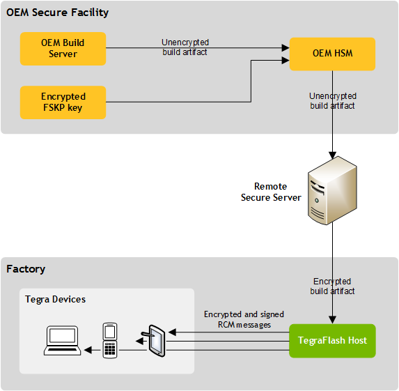
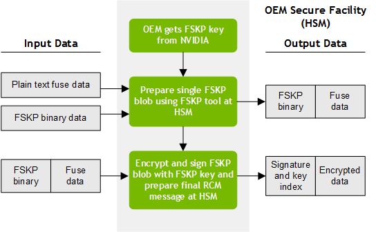
Basic FSKP Fuse Burning Flow
1. Prepare encrypted and signed blob at a secure facility using the FSKP key for the OEM.
The secure facility can be the HSM, or another system component that interfaces with the HSM.
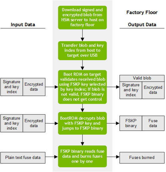
2. Perform fuse-burning at factory floor by downloading the encrypted and signed blob to the factory floor, and send it to a target device for fuse burning.
Sharing an FSKP Key with the OEM
NVIDIA has a formal process to assign an FSKP key to an OEM. The participants in the process are:
• An FSKP owner who requests an FSKP key on behalf of the OEM.
• A key custodian who provides the key on behalf of NVIDIA.
The process ensures that:
• The OEM request is legitimate.
• The OEM is issued a valid, unique key.
• The key is communicated to the OEM securely.
The steps are as follows:
1. The OEM generates an RSA key pair, called the FSKP-owner key pair.
2. The OEM uses this key pair to generate a self-signed X.509 certificate (CER), which the OEM emails to NVIDIA.
The certificate contains the OEM’s public key and a certificate generated with the OEM’s private key.
3. The FSKP owner attaches the CER to an email and sends it to the key custodian.
Microsoft Outlook blocks attachments that have the filetype CER. To ensure NVIDIA receives the certificate, change the filetype before attaching it to the email.
For more information, see Generating and Verifying the Self-Signed X.509 Certificate.
4. The FSKP owner sends an official FSKP key request to NVIDIA.
Such requests are traced, logged, and auditable. The NVIDIA FSKP key policy limits sharing of an FSKP key, other than the debug key, to the requesting customer.
5. NVIDIA verifies the public key submitted by the FSKP owner.
The key custodian contacts the FSKP owner to verify the authenticity of the request and the correctness of the customer key. Contact may be accomplished by a phone call, a face-to-face meeting, an authenticated, encrypted email, or any other agreed means.
The key custodian reads the certificate’ thumbprint which is a computed hash code of the whole certificate to the FSKP owner, who verifies it by comparing it to the thumbprint of their copy of the certificate.
This verification process must be followed for test keys as well.
6. The key custodian selects an available FSKP key from the NVIDIA FSKP Key Allocation Table and assigns it to the OEM.
7. The key custodian loads the FSKP owners public key into the NVIDIA HSM. The custodian directs the HSM to:
• Get the FSKP key assigned to the OEM
• Encrypt the FSKP key with the OEM’s public key
• Generate a Key Code Verification (KCV) for the OEM’s encrypted FSKP key
This process enables NVIDIA to export the FSKP key securely to the OEM over an insecure channel. The encrypted FSKP key can be decrypted with the FSKP private key of the owner.
8. The key custodian sends the FSKP owner an email containing these items:
• FSKP key index
• Encrypted FSKP key
• The KCV, which the FSKP owner can use to verify the FSKP key
9. The FSKP owner incorporates the assigned FSKP key into the OEM’s secure signing flow by importing it into their HSM server and verifying it using the KCV.
Generating and Verifying the Self-Signed X.509 Certificate
The self-signed X.509 certificate is the certificate that the FSKP owner emails to the key custodian.
The requirements for generating and verifying the certificate are as follows:
• A Microsoft Windows system with Java SE 7 or Java SE 8 installed
• The Java key tool utility (keytool), see:
https://docs.oracle.com/javase/7/docs/technotes/tools/windows/keytool.html
• The OpenSSL toolkit, see:
To generate an RSA key pair and create a certificate with the public key
1. On Windows, create a directory to store the private and public key:
mkdir c:\CKMS
2. Navigate to the Java directory that contains the keytool utility:
cd c:\<Java>\Java\jre<version>\bin\
Where:
• <Java> is the directory where Java is installed.
• <version> is the JRE version number.
3. Generate a Java keystore and an RSA key pair and place the key pair in the Java keystore:
keytool.exe -genkeypair -alias <alias> -keyalg RSA -keysize 2048 -sigalg SHA1withRSA -dname "cn=vlsi.tegra,dc=nvidia,dc=com" -ext KU=digitalSignature,keyEncipherment -validity 3650 -keystore "C:\CKMS\mykeystore.jks" -v
• Where <alias> is an alias by which keytool.exe can identify the keypair. The alias is arbitrary except that it must be unique in the Java keystore. It is used as the basename of the CER (certificate) file.
A Java keystore (JKS) is a storage area in the Windows file system in which the Java key tool utility stores cryptographic keys and certificates.
4. When prompted, enter a password to access the keystore.
5. When prompted, enter a password to access the RSA key pair.
For best practices, always protect keys and key stores with strong passwords.
6. Export the public key to a certificate (CER) file.
keytool.exe -export -alias <alias> -file c:\ckms\<alias>.cer -keystore
Where <alias> is the alias assigned to the keypair.
When you are prompted, enter the path to the Java keystore.
The Java key tool utility:
• Creates the CER file with the specified name.
• Stores the certificate in the CER file and the Java keystore.
• Displays the pathname of the Java keystore, such as:
c:\ckms\mykeystore.jks
7. Email the CER file to the key custodian at NVIDIA.
Exporting the OEM’s RSA Private Key to a PEM File
For best practices, save the RSA key pair and certificate in a Privacy-Enhanced Mail (PEM) file. The certificate chain, including the public key, private key, and root certificates, are stored in a PEM file. In contrast, the CER file contains the certificate and the public key.
To export the FSKP owner’s RSA private key to a PEM file
1. Transform the keystore from JKS format to P12 format:
keytool.exe -v -importkeystore -srckeystore c:\ckms\mykeystore.jks -destkeystore c:\ckms\mykeystore.p12 -deststoretype PKCS12
2. When prompted, enter a password for a new PKCS12 keystore.
3. When prompted, re-enter the password for the PKCS12 keystore.
4. When prompted, enter the password for the JKS keystore that was created when the RSA key pair was generated.
5. Using OpenSSL, export the private key from the keystore to a PEM file.
For example:
openssl pkcs12 -in c:\ckms\mykeystore.p12 -out c:\ckms\JohnPrivate.pem -nodes
In the example, the private key is stored in JohnPrivate.pem.
For best practices, keep the PEM file private since it contains the private key.
Verifying the OEM’s Public Key with NVIDIA
The key custodian at NVIDIA contacts the FSKP owner at the OEM to verify the FSKP key request and the integrity of the OEM’s public key. The contact may be made by any confidential means, such as a phone call or a private face-to-face meeting. The key custodian reads the thumbprint to the FSKP owner, who verifies it by comparing it to their own copy of the thumbprint.
To verify the FSKP owner’s public key with NVIDIA
1. The FSKP owner and the key custodian make contact by any agreed confidential means.
2. The FSKP owner and the key custodian each double click the CER file, which opens the file in Crypto Shell Extensions.
3. The FSKP owner reads the certificate’s thumbprint out loud to the NVIDIA key custodian, who verifies it at his end. (The thumbprint is a string of 20 pairs of hexadecimal digits, for example, “25 07 f3 f1 00 88 f8 98 02 2f 1b 2d 03 2e 2a 4b ab e5 e3 9b.”)
System Requirements
The system must be designed to meet the guidelines in the Tegra X2 Interface Design Guideline document, available from your account’s NVIDIA Applications Engineer (AE). This ensures that the fuses are correctly programmed and reliable.
The fuse burning voltage vpp_fuse need be present only when the fuses are being burned, and not when the fuses are being read during boot.
System Circuit Requirements
The circuit requirements for certain fuses is as follows.
• The SoC requirements include:
Parameter | Description | Value | Unit | ||
|---|---|---|---|---|---|
Min | Typ | Max | |||
VPP_FUSE | Programming voltage. | 1.71 | 1.8 | 1.98 | V |
VDD_CORE | Xavier core logic voltage | 0.72 | 0.8 | 0.88 | V |
IPROG | Programming current level required to set a fuse to the programmed state. Must be sustained at vpp_fuse for a minimum duration of FUSETIME_PGM2_TWIDTH_PGM_NANOSECONDS.* | 120 | mA | ||
VPP_FUSE SlewRate0 | From 0 to 0.5V. | 0.5 | V/μsec | ||
VPP_FUSE SlewRate1 | From 0.5V to vpp_fuse. | 0.06 | V/μsec | ||
*Consult the NVIDIA Xavier SoC Processor Technical Reference Manual (TRM) for details. | |||||
Voltage Source Requirements
For best practices, ensure that the VPP_FUSE is connected to the main VDD_1V8 because the Xavier device fuse block has an internal power gate. If fuses are burned during manufacturing, the fuse voltage may be applied through a bed of rails tester, provided that it complies with the circuit requirements.
If the VDD_1V8 power rail is used, it must be checked to confirm that it meets the slew rate requirements.
Temperature Requirements
The acceptable temperature range for burning fuses is 29° C to 101° C. If the temperature is out of range, the FSKP fuse burning tool does not burn the fuses.
No Power Failure or System Reset During Fuse Burning
Fuse burning is a critical operation, and some of the Xavier fuses are interdependent. If there is a power failure while fuse burning is under way and some of the fuses are not burned, the target device may become unusable. For the same reason, it is critical that neither a power failure nor a system reset occur during fuse burning.
USB Recovery Mode Must Be Available
For FSKP to work, USB Recovery Mode must be available. It uses the same port that is used for flashing.
The encrypted fuse data and RCM commands are shared between host and target over USB, so the target must be placed in USB Recovery Mode before starting fuse burning using FSKP.
Target Must Not Be Fused Already
FSKP requires that the fuses which enable secure-boot functionality not be burned on the target. Therefore, the fuses must not be burned prior to using FSKP. These fuses include:
• BootSecurityInfo
• PublicKeyHash
• SecurityMode
FSKP Key Must Be Available to the OEM
NVIDIA provides a unique FSKP key to each OEM. The OEM must use this key to encrypt fuse data. See Sharing an FSKP Key with the OEM, above, for details.
eMMC or UFS Device Must Be Powered
The PMIC is not explicitly programmed during FSKP boot. The eMMC or UFS device must be powered, and pins associated with eMMC or UFS device must not be driven externally during the fuse burning process, if:
• The eMMC or UFS device is a boot device, or
• RPMB provisioning is being done on this device along with fuse burning.
The Fuse Burning Toolkit
FSKP fusing scripts include:
• fskp_fuseburn.py: Provides a higher-level script that is invoked by the user. The script prepares encrypted and signed blobs and performs fuse burning. It invokes other tools based on the input parameters provided.
• fskp_helper.py, fskp_parser.py, and fskp_shell_helper.py: helper scripts for the fskp_fuseburn.py scripts.
FSKP tools include:
• tegraparser_v2: Parses a fuse XML configuration file and uses it to generate a blob containing fuse data and an FSKP target-binary.
• tegrarcm_v2: Manages communication between host and target. It exchanges data and commands over USB with target’s BootROM and bootloader.
• tegrasign_v2: Encrypts and signs an input image with a specified key.
• tegrabct_v2: Creates BR_BCT, MB1_BCT and derivatives key binaries used for encrypting and signing for fskp_blob.
• tegrahost_v2: Appends necessary header and brushes binaries to help in signing and encrypting of the given binary.
• fskp.bin: The FSKP target-binary; a minimal bootloader that is used for burning fuses and writing to storage. It optionally performs RPMB provisioning as well.
• Fuse configuration file: An XML file that contains the fuse list that is read by the tegraparser_v2 tool. The fuse list specifies the name, length, and value of each fuse to be burned, in the order that they are to be burned.
• BR_BCT device configuration file: A configuration file that contains boot device parameter, dev_params, required to generate BR_BCT and derivative key binaries.
• MB1_BCT device configuration files: Platform specific files like PINMUX and PAD settings require generated MB1_BCT files.
• mb1_t194 prod.bin: MB1 bootloader binary required in the platform FSKP path.
• Soft fuse configuration file: A configuration file required for soft fuses by MB1 in platform FSKP boot path.
FSKP Fuse Burn Script
The FSKP fuse burn script, fskp_fuseburn.py, used to be a bash script fskp_fuseburn.sh in previous releases.
To use the fskp_fuseburn.py tool, the Python programming software must be installed on the host system.
fskp_fuseburn.py performs these tasks:
• Parses the fuse configuration file and prepares a blob containing fuse data and an FSKP target-binary.
• Encrypts and signs the blob with the input key.
• It signs MB1 and optionally creates MB1-BCT.
• Downloads MB1 to the target and optionally downloads MB1-BCT on the target using USB recovery mode commands.
• Downloads the blob to the target using USB Recovery Mode commands and performs fuse burning.
• Optionally performs RPMB provisioning.
The script is located at:
<top>/drive-t194ref-foundation/tools/host/flashtools/fuseburn
The script executes on the host. It accepts the arguments shown in the following table.
Argument | Description |
--help (or -h) | Displays the help menu. |
--burnfuse (or -b) | Performs fuse burning. |
--board (or -B) | Board name for which you want create fuse blob or program fuses. Check help for default supported boards. |
--chip (or -c) <chip> | Sets tegra chipid. For example: 0x19 for Xavier SoC. |
--ecid (or -e) | Gets ECID of the target. |
--fusefile (or -f) <file> | Specifies the fuse configuration file. |
--outdir (or g) <path> | Generates blob at <path> and does not perform a burn. |
--keyindex (or -j) <index> | SoC RSKP key index allotted to the OEM. |
--key (or -k) | FSKP key file provided to OEMs as pre the keyindex. |
--rpmb (or -r) <device> | Performs the RPMB key provisioning on the given storage device, emmc or ufs. |
--skipconfirmation (or -s) | Skips the confirmation message while burning the fuse. |
--test (or -t) | Performs a dummy operation; does not burn fuses. |
--skipuid (or -u) | Skips querying UID of the target |
--verbose (or -v) | Enables verbose logs. |
--prebuilt (or -P) <path> | Picks a pre-built blob from <path>; does not generate a the blob. |
--version (or -V) | Identifies the version number. |
Fuse Configuration File
The fuse configuration file is an XML file that contains the fuse data. The tegraparser_v2 tool parses this file and uses it to generate a blob of fuse configuration data.
Note: | Although the fuse configuration file contains XML tags, it does not need the “<?xml... ?>” prolog defined by the XML standard. Fuse configurations may not have a prolog. If you want to run general purpose XML utilities on such a file, you may have to add a prolog. |
For information about the format of the fuse configuration file, see The Fuse Configuration File.
The fuse burn script burns fuses in the order they are specified in the fuse configuration file. It does not check for fuse dependencies. You must ensure that the fuse configuration file specifies fuses in an order that does not burn any dependent fuses before the fuses they depend upon.
Adding New Platform Support to the Fuseburn Tool
Adding a new platform is only required when you want to perform Replay Protected Memory Block (RPMB) provisioning on Universal Flash Storage (UFS) device along with the fuse burning.
For EMMC RPMB provisioning adding board support is not required as the default configuration works. i.e., –board or -B option itself is not required.
For UFS provisioning, the FSKP boot flow is a bit different. The UFS device needs PHY LANE configuration to access the device, which is platform specific. Microboot1 (MB1) configures pinmux and lane reading MB1_BCT to enable device access in FSKP flow. You must pass the device specific pinmux, pad, and lane information to the tool to create platform specific MB1-BCT.
The fuseburn tools support the following boards by default:
• e3550b01-t194a
• e3550b01-t194b
• e3550b03-t194a
• e3550b03-t194b
To add a new platform
1. Edit class fskp_supported_boards in fskp_parser.py.
2. Add your board name in the supported_board_dict dictionary. For example, suppose your board name is tegraxy-a01. Add a line in dictionary: tegraxy-a01 : tegraxyz, The alias is a reference that helps when you have multiple targets using the same configuration files.
3. Add the configuration file for your platform. To determine which files are used for your platform, consult the bootburn_helper.sh file. For more information, see Flashing.
elif self.supported_board_dict[target] == "":
self.mb1_bct_misc_cfg = "tegra194-mb1-bct-misc-auto.cfg"
self.mb1_bct_prod = "tegra194-mb1-bct-prod- tegraxy-a01.cfg"
self.mb1_bct_pinmux = "tegra194-mb1-bct-pinmux-gpio- tegraxy-a01.cfg"
self.mb1_bct_uphy = "tegra194-mb1-bct-uphylane- tegraxy-a01.cfg"
self.board_path = "tegraxyz"
These files must be present in the specific directory path for the tool to pick them up correctly. Copy them over if they are not present. The following table points shows the file name relative to the drive-t186ref-foundation directory. alias-name is the string you set in board_path in support_board_dictionary. You may need to create a directory with the same name as board_path at drive-t186ref-foundation /platform-config/hardware/nvidia/platform/t19x/automotive/bct.
S. No | File name | Relative location |
1 | mb1_bct_misc_cfg | platform-config/bct/t19x |
2 | mb1_bct_prod | platform-config/hardware/nvidia/platform/t19x/automotive/bct/<alias-name>/prod |
3 | mb1_bct_pinmux | platform-config/hardware/nvidia/platform/t19x/automotive/bct/<alias-name>/pinmux |
4 | mb1_bct_uphy | platform-config/hardware/nvidia/platform/t19x/automotive/bct/<alias-name>/ uphy-lanes |
4. Use the board name above with the –board param on fskp_fuseburn tool.
Preparing an Encrypted and Signed Blob
The FSKP blob encryption and signing is performed using derived keys as follows:
1. Call tegraparser_v2 to parse the fuse configuration file and prepare a blob containing fuse data and an FSKP target-binary.
2. Call tegrarcm_v2 to parse dev_param, tegra194-br-bct-qspi.cfg, file to generate the derived string binaries..
3. Call tegrasign_v2 to generate the derived keys using derived string binaries and the OEM FSKP key.
4. Call tegrahost_v2 to align the binary. Then call tegrasign_v2 to encrypt the FSKP target binary blob with the encryption key generated in the previous step.
5. If the board name is provided, call tegrabct_v2 to create MB1-BCT using pinmux, pad, lane-phy configuration, and misc configuration files.
6. Call tegrahost_v2 to append the BCH header on the encrypted FSKP target binary blob.
7. Call tegrasign_v2 to sign the encrypted binary in step 4.
8. Call tegrahost_v2 to fill the FSKP encrypted blob signature in the BCH header.
9. If the board name is provided, call tegrahost_v2 to append BCH to the MB1-BCT created in step 5. Call tegrasign_v2 to create the signature of MB1-BCT and call tegrahost_v2 to update the signature in MB1-BCT BCH.
10. Call tegrahost_v2 to append and fill the signature on the MB1 binary.
11. Call tegrarcm_v2 to generate RCM messages with derivative strings and the FSKP key index filled.
12. Call tegrasign_v2 to sign the RCM messages.
13. Call tegrarcm_v2 to again to update the signature in the RCM message headers.
To prepare the encrypted and signed blob
1. Perform these steps:
• Add derivative strings used to identify which derivative key is generated.
• Edit the configuration file located at:
<top>/drive-t186ref-foundation/platform-config/bct/t19x/bootrom/tegra194-br-bct-qspi.cfg
• Add the 32 bytes derivative string, in hex format as follows:
SecProvisionDerivationString1 = 0x0123456789abcdef00112233445566778899aabbccddeeff0102030405060708;
SecProvisionDerivationString2 = 0x1111111122222222333333334444444455555555666666667777777788888888;
2. Navigate to the utilities scripts directory:
<top>/drive-t186ref-foundation/tools/host/flashtools/fuseburn
3. Execute the fuseburn command:
./fskp_fuseburn.py -f <fuse_config> -i <key_index> -k <FSKP_key> -g <out> -c <chip>
Where:
• <fuse_config> is the fuse configuration file
• <key_index> is the FSKP key index
• <FSKP_key> is the FSKP key
• <out> is the directory where the command is to write its output
• <chip> is the chip for which the FSKP blob is generated
This command prepares an encrypted and signed blob and RCM messages, as described above. It stores the RCM messages and the encrypted FSKP blob in the <out> directory. The output directory <out> can be used on the factory floor for fuse burning.
Interfacing with the HSM
The signing tool tegrasign_v2 does not interface with the HSM. You, the OEM, must provide the interface. There are two ways you can do it:
• Run the fuse burn script, or the several tools it invokes, on the HSM server. This generates a blob as explained above.
• Implement your own signing tool that interfaces with the HSM. Name this tool tegrasign_v2 and copy it to the directory where the FSKP toolkit is stored. The fuse burn script then uses this tool instead the signing tool provided by NVIDIA.
Burning Fuses in the Factory
Use the fuse burn script, fskp_fuseburn.py, to burn fuses in the factory. The script uses tegrarcm_v2 to communicate with the target over USB and sends the blob to the target.
To prepare a system for burning fuses
1. Download the encrypted and signed blob from the secure facility and store it in the directory <top>/out.
2. Put the target into USB Recovery mode.
To burn the fuses
1. Navigate to the utilities scripts directory:
<top>/drive-t186ref-foundation/tools/host/flashtools
2. Execute the fuseburn command:
./fskp_fuseburn.sh -P ./out -b -c 0x19
Upon successful execution the fskp_fuseburn script printout is as follows:
• On the host:
FSKP execution successful
• On the target:
Burning fuses successful
Note: | To ensure that the fuse burn script command and its input sources are correct before you try to burn the fuses, run the script with the --test or -t option. This makes the fuse burn script check its options and inputs for validity, without actually burning the fuses. |
RPMB Provisioning
The Replay Protected Memory Block (RPMB) is a special partition on eMMC and UFS devices that stores data in an authenticated and replay-protected manner. RPMB partition attribute and size on an eMMC or UFS is vendor specific.
RPMB provisioning is the process of creating and configuring an RPMB. It can be accomplished using the fuse burn script.
Prerequisites
• The Kek1 fuse has been burned with a valid key.
If the Kek1 fuse is not already burned, it must be present in the blob provided as input to the fuse burn script. In that case, the script first burns the fuse with the provided value and then performs RPMB provisioning.
To perform RPMB provisioning
1. Set up the system as explained in To prepare a system for burning fuses.
2. Change the current directory to:
<top>/drive-t186ref-foundation/tools/host/flashtools/fuseburn
3. To perform RPMB provisioning on the eMMC device, execute the command:
./fskp_fuseburn.sh -P ./out -b -r emmc -c 0x19
4. To perform RPMB provisioning on the UFS device, execute the command:
./fskp_fuseburn.sh -P ./out -b -r ufs -c 0x19
Where the directory ./out contains the blob downloaded from the secure facility.
You can perform RPMB provisioning along with burning other fuses. If you elect to perform RPMB provisioning separately, the Kek1 fuse must have already been burned, or you must burn it concurrently by including it in the fuse list in the fuse configuration file.
On successful provisioning of the RPMB device partition, logs similar to the following are displayed on the target console:
[0316.769] I> RPMB key provisioned successfully
[0316.774] I> Rollback Provisioning successful
The Fuse Configuration File
The fuse configuration file is an input to the fuse burn script, fskp_fuseburn.sh. It contains list of fuses and the value to be burned in each fuse. The script calls the tegraparser_v2 tool to parse the fuse configuration file and generate the blob.
Format of the Fuse Configuration File
A fuse configuration file contains a <genericfuse>… </genericfuse> tag pair, which contains one <fuse/> tag for each fuse to be burned. This template shows the format of the file.
<genericfuse MagicId="0x45535546" version="1.0.0">
<fuse name="<name>" size="<size>" value="<value>"/>
<fuse name="<name>" size="<size>" value="<value>"/>
. . .
</genericfuse>
Where:
• <name> is the name of a fuse. Fuse names are documented in the table under Manufacture Programmable Fuses.
• <size> is the size of the fuse in bytes.
• <value> is the value to be burned into the fuse, with two hexadecimal digits per byte.
MagicID is used by the FSKP target-binary, and must not be changed.
tegraparser_v2 burns fuses in the order that they appear in the fuse configuration file. If two or more fuses’ values are interdependent, the independent fuses must be specified before the dependent one so that they are burned first. That is, if the values that may be burned into fuse Z depend on the value of fuse Y, and the values that may be burned into fuse Y depend on the value of fuse X, then the fuse configuration file must specify fuse X first, then Y, then Z, so that tegraparser_v2 burns fuse X first, then Y, then Z.
Caution: | The FSKP fuse burning tool does not check for dependencies, so specifying a dependent fuse before the fuse it depends on may render the target device inoperable. Check the fuse list’s order carefully before you burn the fuses. |
A Reference Fuse Configuration File
The DRIVE platform provides a fuse configuration file for use as a reference. The file is located at:
<top>/drive-t186ref-foundation/tools/host/flashtools/fuseburn
The fuse list for this file is ordered correctly to allow for fuse dependencies.
Some fuse values in the reference configuration file are enclosed in XML comments, as in the following example. To adapt the reference file for use, uncomment them and replace their “0xFFFF…” placeholder values with the actual key index values for your target.
<genericfuse MagicId="0x45535546" version="1.0.0">
<!-- <fuse name="OdmId" size="8" value="0xFFFFFFFFFFFFFFFF"/> -->
<!-- <fuse name="ReservedOdm0" size="4" value="0xFFFFFFFF"/> -->
<!-- <fuse name="ReservedOdm1" size="4" value="0xFFFFFFFF"/> -->
<!-- <fuse name="ReservedOdm2" size="4" value="0xFFFFFFFF"/> -->
<!-- <fuse name="ReservedOdm3" size="4" value="0xFFFFFFFF"/> -->
<!-- <fuse name="ReservedOdm4" size="4" value="0xFFFFFFFF"/> -->
<!-- <fuse name="ReservedOdm5" size="4" value="0xFFFFFFFF"/> -->
<!-- <fuse name="ReservedOdm6" size="4" value="0xFFFFFFFF"/> -->
<!-- <fuse name="ReservedOdm7" size="4" value="0xFFFFFFFF"/> -->
<fuse name="OdmInfo" size="4" value="0x4000"/>
<fuse name="SecureProvisionInfo" size="4" value="0x1"/>
<fuse name="Kek0" size="16" value="0xffefddfcffbe1299ef7767d57c773613"/>
<fuse name="Kek1" size="16" value="0x79239468583412811705273178573423"/>
<fuse name="Kek2" size="16" value="0x45239178563412896745239178563412"/>
<fuse name="PublicKeyHash" size="32" value="0xe9408581e4aa94bf57ab3b907764b27698ae1706badfde10dc08afbd81e3acf7"/>
<fuse name="BootSecurityInfo" size="4" value="0x2"/>
<fuse name="SecureBootKey" size="16" value="0x37231668553412812705270178773423"/>
<fuse name="SecurityMode" size="4" value="0x1"/>
</genericfuse>
About Fuse Properties
The Tegra device contains two types of fuses for ODM use:
• Manufacture fuses, which must be programmed during the manufacturing process
• Field programmable fuses, which may be programmed during the lifetime of the product by the ODM for software to use
Typical applications of a field programmable fuse are incrementing a version number for software updates to prevent users from running an old version of software, and storing a serial number or date of first use.
Manufacture Programmable Fuses
NVIDIA Tegra devices contain many manufacture programmable fuses that control different items for security and boot.
The manufacture programmable fuses include:
• Fuse Name—the name that you use to identify a fuse in the fuse configuration file. Examples of fuse names are SecurityMode, JtagDisable, and DebugAuthentication.
• Fuse Symbol—the name that you use to identify the fuse in software. It is in the same column as the Fuse Name, but is in all caps. The fuse symbols that correspond to the fuse names above are FUSE_SECURITY_MODE, FUSE_ARM_JTAG_DIS, and FUSE_DEBUG_AUTHENTICATION.
• Register Name—the name of the hardware register that holds the fuse value, if it is different from the Fuse Symbol. It is in the same column as the Fuse Name and Fuse Symbol, but is in italic type. Some fuses are represented by more than one register, and in such cases the table presents all of the registers’ names.
• Description—describes the fuse.
• Fuse size—the size of the fuse value in bytes. When you program a fuse with a <fuse> tag in the fuse configuration file, you must specify its size in the tag’s size property.
• Bit length—the length of the fuse value in bits. This refers to the value’s internal length in the fuse register(s). It is in the same column as Fuse Size, but is in brackets, for example: [1].
The platform fuse description is as follows:
Xavier SoC Fuse Description | ||||
|---|---|---|---|---|
Fuse Name FUSE SYMBOL Register Name | Description | Fuse Size [Bit Length] | Notes | |
SecurityMode FUSE_SECURITY_MODE | ODM Production Mode: Also known as ODM Security Mode. This fuse write protects all manufacturing device fuses against any further fuse programming and hides the SBK values. This fuse must be programmed last. | 4 [1] | ||
JtagDisable FUSE_ARM_JTAG_DIS | ARM JTAG Disable: Completely disables the external debug paths; including ARM JTAG path and USB SWD path. This field compliments the ARM debug authentication field. | 4 [1] | Note 3 | |
DebugAuthentication FUSE_DEBUG_AUTHENTICATION | ARM Debug Authentication Provides fine control of ARM debug capabilities. Programming one of these fuses permanently disables the equivalent debug capability: • Bit 0 forces dbgen to 0 • Bit 1 forces niden to 0 • Bit 2 forces spiden to 0 • Bit 3 forces spniden to 0 • Bit 4 forces deviceen to 0 | 4 [5] | Note 3 | |
SecureBootKey FUSE_SECURE_BOOT_KEY FUSE_PRIVATE_KEY0 /../ FUSE_PRIVATE_KEY3 | Secure Boot Key (SBK) Stores an ODM-supplied secure boot key for each chip. Use of SBK and the authentication scheme selected by fuse_boot_security_info. For example, “0xABCDEF” input value is represented as “0x0000000000ABCDEF.” | 16 [128] | Notes 1, 3, and 4 | |
PublicKeyHash FUSE_PUBLIC_KEY_HASH FUSE_PUBLIC_KEY0 /../ FUSE_PUBLIC_KEY7 | Public Key Hash (PKC) These eight consecutive registers encode a 256-bit hash of the ODM public key. | 32 [256] | Note 3 | |
EndorsementKey FUSE_ENDORSEMENT_KEY FUSE_EK0 [31:0] /../ FUSE_EK7 [31:0] | Endorsement Key This key might be burned in encrypted form, with decryption performed by boot ROM. | 32 [256] | Note 3 | |
SwReserved FUSE_RESERVED_SW | Reserved Bits for Software (read by Boot ROM) | 4 [24] | Note 3 | |
BootDevInfo FUSE_BOOT_DEVICE_INFO | Boot Device Configuration Identifies the OS image boot device configuration. Used in conjunction with the Boot Device Selection to provide its configuration. | 4 [8] | Note 2, 3 | |
BootSecurityInfo FUSE_BOOT_SECURITY_INFO | Boot Security Information Bits interpreted by boot software with following mapping: Bits [1:0] mapped to Secure Boot Authentication Scheme, where 00b: SHA2 Hash 01b: 2048 bit RSA 10b: 3072 bit RSA 11b: ECC (Elliptic Curve, see also bit 7) Bits [2] secure boot encryption scheme, enables encryption using SBK when set to 1 Bits [3] ODM FEK usage enable Bits [6:4] ODM Fuse Encryption Key Select Bits [7] only used if bit 1:0 is set to 11b (elliptic) • 0b = ECDSA with NIST P256 curve • 1b = EdDSA (Ed25519) Bits not listed are reserved. | 4 [16] | Note 3 | |
SecureProvisionInfo FUSE_SECURE_PROVISION_INFO | Factory Secure Provisioning Allows the ODM to control secure provisioning features: [0] is hide bit; The hide bit ([0]) should be programmed *before* programming SBK fuses if the Factory Secure Provisioning feature is being used. | 4 [2] | Note 3 | |
CcplexDfdAccessDisable FUSE_CCPLEX_DFD_ACCESS_DISABLE | CCPLEX Low-Level DFD Access Disable CCPLEX power management DFD Disable access (when fuse is programmed, DFD access is disabled). | 4 [1] | Note 3 | |
Kek0 Kek1 Kek2 Kek256 FUSE_KEK00 FUSE_KEK01 FUSE_KEK02 FUSE_KEK03 FUSE_KEK10 FUSE_KEK11 FUSE_KEK12 FUSE_KEK13 FUSE_KEK20 FUSE_KEK21 FUSE_KEK22 FUSE_KEK23 | Key Encryption Key or Key Seed These 12 consecutive registers can be used to encode some Key Encryption Key and/or some Key Seed, with different combinations of width. | 48 [384] | Note 3 | |
ODMInfo | ODM Information 8 LSB contains the 8 LSB of the USB PID for an USB device used for dead battery boot compliance. Remaining bits are reserved for use by ODM for information that is permanently burned. | 4 [16] | Note 3 | |
OdmId FUSE_ODMID0 FUSE_ODMID1 | ODM ID These 2 consecutive registers encode a 64 bit ODM ID. | 8 [64] | Note 3 | |
SataMphyOdmCalib FUSE_SATA_MPHY_ODM_CALIB | FUSE SATA/MPHY Calibration The two LSB contain calibration information. This field is used by boot before being able to access the BCT. [1:0] Varies SATA/MPHY pad TX_AMP and _PEAK to compensate for different trace lengths [3:2] Reserved for other board dependent calibration | 4 [4] | Note 3, 6 | |
H2 FUSE_H2 | Hamming Code Implement the ECC for the ODM manufacturing fuses. This fuse must be programmed just before burning ODM Production Mode. | 4 [32] | Notes 3, 5, and 6 | |
TestKeyEnable FUSE_FORCE_DEBUG_WITH_TEST_KEYS | Debug with Test Keys Enable Enable the use of test keys when debug is allowed (to protect production key) | 4 [1] | Note 3 | |
BistControl FUSE_SECURE_IN_SYSTEM_BIST_CONTROL | In System BIST Control Indicates to BPMP that in system BIST would be done at power off. The field is a bit map that indicates which DFT engines to trigger in the system: [0] controls Xavier itself, [1] controls an attached dGPU, [2] reserved | 4 [3] | Note 3 | |
Flw2 FUSE_FLW2 | Force Large Weight This bit is used as part of the ECC scheme, burned to 1 to insure field H2 has large enough weight. | 4 [1] | Note 3 | |
OptInEnable FUSE_OPT_CUSTOMER_OPTIN_FUSE | Customer OPTIN Enable Indicates if field programming of NV ratchet fuses for MB1/CCPLEX Unicode are allowed. | 4 [1] | Note 3 | |
Notes | ||||
1 | If encryption is enabled through boot_security_info fuse, SBK is used to decrypt the bootloader and the boot configuration table. Encryption is not currently supported. | |||
2 | Consult the boot options fuse configuration table, Table 5, for the correct boot settings for your platform. | |||
3 | Fuse programming of ODM manufacturing programmable fuses are disabled when the ODM Production Mode fuse = 1. | |||
4 | After programming the value and rebooting the chip, the value is an input to the SSK calculation regardless of whether the ODM Production Mode fuse has been set. | |||
5 | Programming these fuses is performed by the NVIDIA software. | |||
6 | Verify the secure boot software package for the fuse burning operation. | |||
Caution: | Burning a fuse bit (changing its value from 0 to 1) is an irreversible operation. For example, you can change a fuse value of 1 (0b0001) to 3 (0b0011) or 7 (0b0111) by burning the appropriate bits, but you cannot change it to 4 (0x0100), because the 1’s bit can never be reset to 0. You must never allow a system reset to occur during a fuse burning operation. A system reset might cause some programmed fuses to be burned and other left unburned. This in turn could render the target device inoperable. |
The SecurityMode Fuse
The SecurityMode fuse write protects all manufacture programmable fuses, leaving only field programmable fuses subject to change. This fuse must be burned after all ODM fuses have been burned, and before the device is sent to the field. It is critically important to burn this fuse to avoid security attacks that change the device configuration by burning more fuses (as a trivial example, by modifying key values stored in fuses).
Burning this fuse also hides secret keys (see Secret Keys) so that software cannot read them.
During the manufacturing process, fuses must be programmed in this order:
1. All manufacture programmable fuses except those set in steps 2 and 3.
2. The SecurityMode fuse.
Debug Disable
Two fuses impact the ability to debug NVIDIA Tegra® devices ARM® processors.
• The ARM_JTAG_DISABLE Fuse—Burning this fuse permanently disables JTAG access to the debug access port through the JTAG pins on Tegra™ X2. This prevents JTAG access by external ARM debuggers after the product leaves the factory.
Note: | Boundary Scan is possible through the JTAG pins, irrespective of this fuse’s state. |
• The CCPLEX_DFD_ACCESS_DISABLE Fuse—Burning this fuse disables NVIDIA internal CCPLEX debug access on the chip, and so prevents NVIDIA from performing hardware level debugging on the CCPLEX.
DebugAuthentication Fuse
The ARM DebugAuthentication fuse controls the standard ARM debug fuses. This table describes its functions.
Fuse Bit Name | Description | Definition | Common Use Case |
|---|---|---|---|
dbgen | Debug Enable: When set, enables invasive and non-invasive debug of the non-secure state. When not set, access to debug components is generally still permitted, but those components are disabled. | Non-secure invasive debug enable | CPUs to halt; AXIAP to make system accesses; ETR to stream trace to DRAM |
niden | Non-Invasive Debug Enable: When set, enables non-invasive debug operations, such as trace, of the non-secure state. NIDEN can be set independently of DBGEN. | Non-secure non-invasive debug enable | PTM trace from CPUs |
spiden | Secure Privileged Invasive Debug Enable - When asserted along with DBGEN, enables invasive and non-invasive debug of Secure state. | Secure invasive debug enable | AXI_AP to make secure accesses into the system; ETR to write to Secure DRAM |
spniden | Secure Privileged Non-Invasive Debug Enable - When asserted along with NIDEN, enables non-invasive debug of Secure state. | Secure non-Invasive debug enable | Accessing secure registers in PMU and CPUs over the Debug APB |
deviceen | Device Debug Enabled - Enables the external debug tool’s connection to the device. This signal also drives the DBGSWENABLE which is an enable input signal of the CoreSight Components and Cortex-A Series processor. | Device enable | Accessing any device registers that are mapped over the Debug APB |
Secret Keys
The fuses such as SecureBootKey, KEK0, etc. hold secret keys. These fuses must be burned before SecurityMode is burned.
SecureProvisionInfo Fuse
This fuse is used when burning fuses using Factory Secure Key Provisioning (FSKP).
This procedure illustrates one possible security threat that could occur on the factory floor manufacturing fuses are burned:
1. Burn the fuses that specify keys, such as SecureBootKey, Kek0, etc.
2. Burn the SecurityMode fuse.
It is possible to reset the system between steps 1 and 2, and since SecurityMode has not yet been burned, the keys then can be easily read back. The SecureProvisionInfo fuse can prevent this security threat, as the following procedure shows:
1. Burn the SecureProvisionInfo fuse’s bit 0 (the hide bit).
2. Burn the other key fuses such as Kek0, SecureBootKey, etc.
3. Burn the SecurityMode fuse.
Burning the SecureProvisionInfo fuse in step 1 prevents the keys from being read back. Any attempt to read back the keys after step 2 will return a value that is all binary ones.
Note: | The SecureProvisionInfo fuse takes effect only from the next reset of the target after it is burned. Thus the FSKP fuse burning tool can still read back the keys immediately after burning them and compare them to the values it burned to confirm that burning was successful. |
Public Key Hash
These fuses are programmed with the hash of the ODM public key. They take effect only after the BootSecurityInfo fuse has been programmed.
ECC
Individual fuse failures are rare but not impossible events. The fuse logic can correct such failures by using either of two error correcting code (ECC) techniques:
• An OR-ECC, in which two fuses are ORed together to get the corrected value. This code is unidirectional and protects against a 1 bit becoming a 0 bit.
• A Hamming ECC applied to a set of fuses. This type of ECC cab correct one error in the set of fuses protected. The Hamming code has much less overhead than the OR-ECC, but requires groups of bits to be programmed together.
The ECC applied to specific fuses is specified as a per-chip option as part of the global fuse definition table. See the NVIDIA Tegra X2 Processor Technical Reference Manual (TRM). Both ECC methods are transparent to software when using fuse option registers to get access to fuse information, but require some care when programming fuses.
ODM Field Programmable Fuses
The following fuses are available for the system designer to program during the product lifetime, that is, after the product is released to the field. If these fuses are to be field programmed, the fuse programming voltage VPP_FUSE must be present in the system at the time they are burned.
The RESERVED_ODM fuses are split into eight banks of 32 bits each. The first four banks (banks 0 to 3) can be locked out by setting the corresponding bit in the OdmLock fuse. (For example, to lock the ReservedOdm1 fuse, set the OdmLock fuse’s bit 1.) This prevents unintentional programming of other bits in the bank.
ReservedOdm4 through ReservedOdm7 do not have this lock feature.
The table columns are the same as the corresponding columns in the table of manufacture programmable fuses, under Manufacture Programmable Fuses, above.
Fuse Name FUSE SYMBOL Register Name | Fuse Description | Fuse Size Bit Length |
|---|---|---|
ReservedOdm0 through ReservedOdm7 FUSE_RESERVED_ODM0 through FUSE_RESERVED_ODM7 | Customer programmable fuses; remain programmable after fuse_security_mode has been programmed. Default value (when no Reserved ODM fuses have been programmed) is all zeros. One intended application of these fuses is software version revocation. They may be used for other purposes at the customer’s discretion. | 32 256 (8 fuses, 4 bytes or 32 bits each) |
OdmLock FUSE_ODM_LOCK | Each bit disables further changes to one of the ReservedOdm fuses. Only the first four ReservedOdm fuses may be disabled by this means. OdmLock[0] disables ReservedOdm0 OdmLock[1] disables ReservedOdm1 OdmLock[2] disables ReservedOdm2 OdmLock[3] disables ReservedOdm3 | 4 4 |
Fuse Blob Format
This section describes details of the fuse blob format.
The fuse_info Structure
The host sends the information required to burn fuses to the device in a packed binary format defined by struct fuse_info.
fuse_info consists of three parts:
• Header: Stores fuse information that applies to the fuses as a group. This includes the Magic_ID, version, size of blob, number of fuses, and offset of the first fuse node.
• Nodes: An array of fuse nodes containing metadata for each fuse. This includes fuse type, offset of the value in the blob, and size of the value.
• Values: A collection fields containing the value of each fuse, packed without boundary alignment.
Most fuses’ values are less than four bytes long, but a few are much longer. The offset/size design allows fuse_info to store the longest values without wasting space by padding the shorter ones.
This diagram shows the fuse_info layout.
Lowest address | Header | magicid | |
∙ | version | ||
∙ | blobSize | ||
∙ | fuseNum | ||
∙ | fuseEntries | ||
∙ | Nodes | Node 1 | type |
∙ | size | ||
∙ | offset | ||
∙ | Node 2 | ∙ | |
∙ | ∙ | ∙ | |
∙ | ∙ | ∙ | |
∙ | ∙ | ∙ | |
∙ | Node <n> | ∙ | |
∙ | Values | Value 1 | |
∙ | Value 2 | ||
∙ | ∙ | ||
∙ | ∙ | ||
∙ | ∙ | ||
Highest address | Value <n> | ||
struct fuse_node and struct fuse_info Definitions
The following code defines the layout of the fuse_node structure.
/**
* @brief per fuse Entry in the fuse info structure
*
* @param type Identifier for the fuse
* @param size Register size of the fuse
* @param offset Offset of fuse data in the fuse info blob
*/
struct fuse_node {
enum fuse_type type;
uint32_t size;
uint32_t offset;
};
/**
* @brief Header for fuse info
*
* @param magicid magicid for validation
* @param version fuse tool version
* @param infoSize total size for fuse info
* @param fuseNum numbers of fuses in fuse info
* @param fuseEntry offset of the first fuse node in the info
*/
struct fuse_info_header {
uint32_t magicid;
uint32_t version;
uint32_t infosize;
uint32_t fusenum;
uint32_t fuseentry;
};
/**
* @brief The Fuse Info (contains fuse info header and one or more fuse nodes)
*
* @param head pointer to header field in fuse info
* @param nodes pointer to fuse node field in fuse info
* @param data pointer to data field in fuse info
*/
struct fuse_info {
struct fuse_info_header *head;
struct fuse_node *nodes;
uint32_t *data;
};
enum FUSE Definition
The fuse macros are as follows:
#define FUSE_TYPE_BOOT_SECURITY_INFO 0x0
#define FUSE_BOOT_SECURITY_REDUNDANT_INFO FUSE_TYPE_BOOT_SECURITY_INFO
#define FUSE_SEC_BOOTDEV 0x1
#define FUSE_UID 0x2
#define FUSE_SKU_INFO 0x3
#define FUSE_TID 0x4
#define FUSE_CPU_SPEEDO0 0x5
#define FUSE_CPU_SPEEDO1 0x6
#define FUSE_CPU_SPEEDO2 0x7
#define FUSE_CPU_IDDQ 0x8
#define FUSE_SOC_SPEEDO0 0x9
#define FUSE_SOC_SPEEDO1 0xa
#define FUSE_SOC_SPEEDO2 0xb
#define FUSE_ENABLED_CPU_CORES 0xc
#define FUSE_APB2JTAG_DISABLE 0xd
#define FUSE_TPC_DISABLE 0xe
#define FUSE_APB2JTAG_LOCK 0xf
#define FUSE_SOC_IDDQ 0x10
#define FUSE_SATA_NV_CALIB 0x11
#define FUSE_SATA_MPHY_ODM_CALIB 0x12
#define FUSE_TSENSOR17_CALIB 0x13
#define FUSE_TSENSOR_COMMON_T1 0x14
#define FUSE_TSENSOR_COMMON_T2 0x15
#define FUSE_TSENSOR_COMMON_T3 0x16
#define FUSE_HYPERVOLTAGING 0x17
#define FUSE_RESERVED_CALIB0 0x18
#define FUSE_OPT_PRIV_SEC_EN 0x19
#define FUSE_USB_CALIB 0x1a
#define FUSE_USB_CALIB_EXT 0x1b
#define FUSE_TYPE_PRODUCTION_MODE 0x1c
#define FUSE_TYPE_SECURITY_MODE 0x1d
#define FUSE_SECURITY_MODE_REDUNDANT FUSE_SECURITY_MODE
#define FUSE_ODM_LOCK 0x1e
#define FUSE_ODM_LOCK_R FUSE_ODM_LOCK
#define FUSE_ARM_JTAG_DIS 0x1f
#define FUSE_ARM_JTAG_DIS_REDUNDANT FUSE_ARM_JTAG_DIS
#define FUSE_RESERVED_ODM0 0x20
#define FUSE_RESERVED_ODM0_REDUNDANT FUSE_RESERVED_ODM0
#define FUSE_RESERVED_ODM1 0x21
#define FUSE_RESERVED_ODM1_REDUNDANT FUSE_RESERVED_ODM1
#define FUSE_RESERVED_ODM2 0x22
#define FUSE_RESERVED_ODM2_REDUNDANT FUSE_RESERVED_ODM2
#define FUSE_RESERVED_ODM3 0x23
#define FUSE_RESERVED_ODM3_REDUNDANT FUSE_RESERVED_ODM3
#define FUSE_RESERVED_ODM4 0x24
#define FUSE_RESERVED_ODM4_REDUNDANT FUSE_RESERVED_ODM4
#define FUSE_RESERVED_ODM5 0x25
#define FUSE_RESERVED_ODM5_REDUNDANT FUSE_RESERVED_ODM5
#define FUSE_RESERVED_ODM6 0x26
#define FUSE_RESERVED_ODM6_REDUNDANT FUSE_RESERVED_ODM6
#define FUSE_RESERVED_ODM7 0x27
#define FUSE_RESERVED_ODM7_REDUNDANT FUSE_RESERVED_ODM7
#define FUSE_KEK256 0x28
#define FUSE_KEK2 0x29
#define FUSE_PKC_PUBKEY_HASH 0x2a
#define FUSE_SECURE_BOOT_KEY 0x2b
#define FUSE_RESERVED_SW 0x2c
#define FUSE_BOOT_DEVICE_SELECT 0x2d
#define FUSE_SKIP_DEV_SEL_STRAPS 0x2e
#define FUSE_BOOT_DEVICE_INFO 0x2f
#define FUSE_SECURE_PROVISION_INFO 0x30
#define FUSE_KEK0 0x31
#define FUSE_KEK1 0x32
#define FUSE_ENDORSEMENT_KEY 0x33
#define FUSE_ODMID 0x34
#define FUSE_H2 0x35
#define FUSE_ODM_INFO 0x36
#define FUSE_DBG_AUTHENTICATN 0x37
#define FUSE_DEBUG_AUTHENTICATION_REDUNDANT FUSE_DBG_AUTHENTICATN
#define FUSE_CCPLEX_DFD_ACCESS_DISABLE 0x38
#define FUSE_CCPLEX_DFD_ACCESS_DISABLE_REDUNDANT FUSE_CCPLEX_DFD_ACCESS_DISABLE
#define FUSE_RESERVED_ODM8 0x39
#define FUSE_RESERVED_ODM8_REDUNDANT FUSE_RESERVED_ODM8
#define FUSE_RESERVED_ODM9 0x3A
#define FUSE_RESERVED_ODM9_REDUNDANT FUSE_RESERVED_ODM9
#define FUSE_RESERVED_ODM10 0x3B
#define FUSE_RESERVED_ODM10_REDUNDANT FUSE_RESERVED_ODM10
#define FUSE_RESERVED_ODM11 0x3C
#define FUSE_RESERVED_ODM11_REDUNDANT FUSE_RESERVED_ODM11
#define FUSE_CV_DISABLE 0x3D
#define FUSE_CCPLEX_UCODE_NV_REVISION 0x3E
#define FUSE_CCPLEX_UCODE_MB1_FALCON_UCODE_FLD_RATCHET0 0x3F
#define FUSE_CCPLEX_UCODE_MB1_FALCON_UCODE_FLD_RATCHET0_REDUNDANT FUSE_CCPLEX_UCODE_MB1_FALCON_UCODE_FLD_RATCHET0
#define FUSE_CCPLEX_UCODE_MB1_FALCON_UCODE_FLD_RATCHET1 0x40
#define FUSE_CCPLEX_UCODE_MB1_FALCON_UCODE_FLD_RATCHET1_REDUNDANT FUSE_CCPLEX_UCODE_MB1_FALCON_UCODE_FLD_RATCHET1
#define FUSE_CCPLEX_UCODE_MB1_FALCON_UCODE_FLD_RATCHET2 0x41
#define FUSE_CCPLEX_UCODE_MB1_FALCON_UCODE_FLD_RATCHET2_REDUNDANT FUSE_CCPLEX_UCODE_MB1_FALCON_UCODE_FLD_RATCHET2
#define FUSE_CCPLEX_UCODE_MB1_FALCON_UCODE_FLD_RATCHET3 0x42
#define FUSE_CCPLEX_UCODE_MB1_FALCON_UCODE_FLD_RATCHET3_REDUNDANT FUSE_CCPLEX_UCODE_MB1_FALCON_UCODE_FLD_RATCHET3
#define FUSE_MB1_NV_REVISION 0x43
#define FUSE_FORCE_DEBUG_WITH_TEST_KEYS 0x44
#define FUSE_SECURE_IN_SYSTEM_BIST_CONTROL 0x45
#define FUSE_FLW2 0x46
#define FUSE_OPT_CUSTOMER_OPTIN_FUSE 0x47
#define FUSE_FORCE32 0x7FFFFFFF
Example
This example shows a simple fuse configuration file and the blob data that the fuse burn tool generates from it.
<genericfuse MagicId="0x46555345" version="1.0.0">
<fuse name="ReservedOdm0" size="4" value="0x89ABCDEF"/>
<fuse name="SecureBootKey" size="16" value="0x123456789ABCDEF0123456789ABCDEF0"/>
</genericfuse>
This table shows the hexadecimal contents of the resulting blob data.
Offset | 0 | 1 | 2 | 3 | 4 | 5 | 6 | 7 | 8 | 9 | A | B | C | D | E | F |
000x | 45 | 53 | 55 | 46 | 01 | 00 | 00 | 00 | 40 | 00 | 00 | 00 | 02 | 00 | 00 | 00 |
001x | 14 | 00 | 00 | 00 | 20 | 00 | 00 | 00 | 04 | 00 | 00 | 00 | 2C | 00 | 00 | 00 |
002x | 2B | 00 | 00 | 00 | 10 | 00 | 00 | 00 | 40 | 00 | 00 | 00 | EF | CD | AB | 89 |
003x | F0 | DE | BC | 9A | 78 | 56 | 34 | 12 | F0 | DE | BC | 9A | 78 | 56 | 34 | 12 |
This table explains the contents of the sample file and the blob generated from it.
XML Tag & Property | Offsets in Sample Blob | Description |
|---|---|---|
Header | ||
<genericfuse> | 0x00-0x13 | Header |
MagicId | 0x00-0x03 | A fixed value that identifies the generated data structure as a valid fuse data blob. |
version | 0x04-0x06 | Blob format’s version number. Provides backward compatibility for future extensions to the fuse data format. In XML, three numbers separated by dots. In a blob, three one-byte unsigned integers. |
‒ | 0x07 | Unused. |
‒ | 0x08-0x0B | Blob size in bytes. |
‒ | 0x0C-0x0F | Number of fuses in blob. Derived from the number of <fuse> tags. |
‒ | 0x10-0x13 | Offset of first fuse value. |
Fuse nodes | ||
<fuse> | 0x14-0x1F | First fuse definition in XML; corresponding fuse node in blob. |
name | 0x14-0x17 | Fuse name in XML; corresponding fuse type code in blob (in this case FuseReservedOdm0). |
size | 0x18-0x1B | Length of value in bytes (in this case 4). |
‒ | 0x1C-0x1F | Offset of value (in this case 0x0000002C). |
Fuse Values | ||
<fuse> | 0x20-0x2B | Second fuse definition in XML; corresponding fuse node in blob. Fuse type code is SecureBootKey; length of value is 16; offset of value is 0x00000030. |
value | 0x2C-0x2F | First fuse value. |
value | 0x30-0x3F | Second fuse value. |