Radar Calibration - Operating Principle
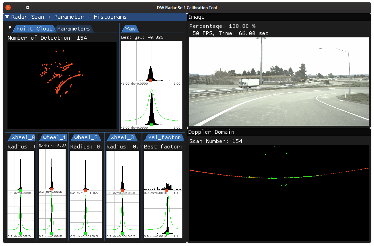
Radar calibration estimates the current sensor orientation (yaw angle) with respect to the vehicle's coordinate frame. This yaw angle is estimated by first using the Doppler signal of radar detections to estimate the radar's motion. Subsequently, the radar motion is matched with vehicle yawrate estimates to estimate the yaw angle. Calibration measurements require a sufficiently large speed of driving.
The Doppler motion observed by a radar can also be used to calibrate odometry speed factors, i.e., a factor which maps measured longitudinal speed to the actual driven speed. In addition the method can be used to calibration individual wheel radii by looking for the radius which maps wheel's rotational velocity to the longitudinal velocity measured by radar. If requested, this calibration will be performed during straight driving maneuvers.
Requirements
Initialization Requirements
- Nominal values on radar calibration
- Orientation(roll/pitch/yaw): less than 10 degree error
- Position(x/y/z): x and y are not used for now, z is less than 10 cm error
Input Requirements
- Sensors: radar calibration requires data from radar and CAN sensors.
- dwVehicleIOState: to perform radar calibration, dwCalibrationEngine has to be fed with
dwVehicleIOState, with information parsed from received CAN events. - Assumption: Vehicle performs normal driving maneuvers until calibration convergence.
Output Requirements
- Corrected yaw value: less than 0.1 degrees
- Time to correction: less than 2 minutes for radar sensor with 15HZ spinning frequency
Cross-validation KPI
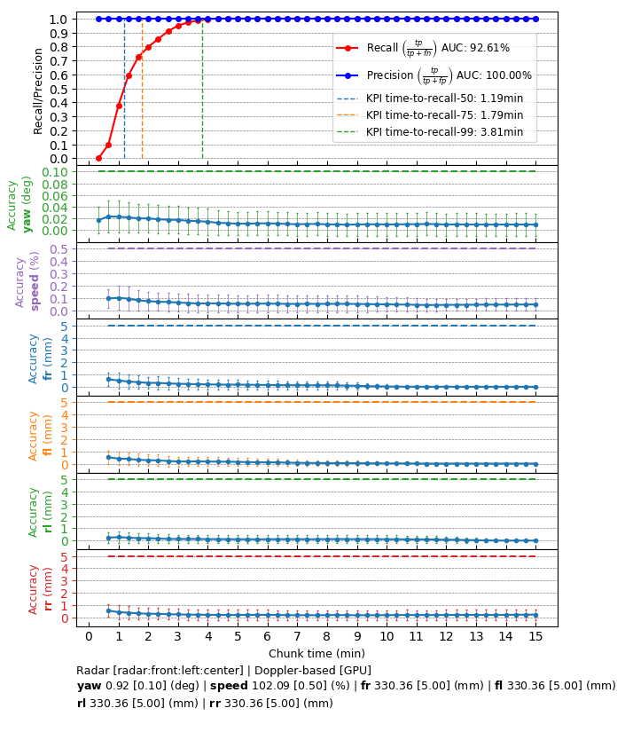
Several hours of data are used to produce a reference calibration value for cross-validation. Then, short periods of data are evaluated for whether they can recover the same values. For example, the graph below shows precision/recall curves of radar self-calibration. Precision indicates that an accepted calibration is within a fixed precision threshold from the reference calibration, and recall indicates the ratio of accepted calibrations in the given amount of time.
Workflow
The following code snippet shows the general structure of a program that performs Radar self-calibration
This workflow is demonstrated in the following sample: Radar Calibration Sample