Network Logical Architecture#
This Enterprise RA uses a spine-leaf network providing physical fabrics for the use-cases and requirements shown in Table 4:
Table 4: Fabric Roles and Usage Recommendations
Fabric Roles |
RDMA/RoCE Support |
AI Training, Fine tuning, ML or HPC |
Pure Inference |
Storage connectivity |
|---|---|---|---|---|
GPU Compute (East/West) |
Recommended |
Recommended |
Optional |
Not Recommended |
CPU Converged (North/South) |
Optional |
Recommended |
Recommended |
Recommended |
Storage |
Optional |
Recommended |
Recommended |
Recommended |
Customer |
Not applicable |
Recommended |
Recommended |
Optional |
Support Servers |
Optional |
Recommended |
Recommended |
Optional |
OOB Management |
Not applicable |
Recommended |
Recommended |
Not Applicable |
Deeper explanations of each of the fabric roles are below:
GPU Compute (East/West) Network
The GPU Compute (East/West) network is an RDMA based fabric in a leaf-spine architecture where the GPUs are connected using a rail-optimized network topology through their respective SuperNICs. This design allows the most efficient communication for multi-GPU applications within and across the compute nodes.
In the architectures below for smaller design points the Compute Fabric has been merged with the Converged Fabric. This is to lower cost and to simplify the network architecture.
For larger network design points due to the high number of endpoints required the Compute Fabric utilizes a super-spine, spine and leaf networking architecture. This is principally to support the required design points but also to allow extensibility in the architecture.
CPU Converged (North/South) Network
The CPU Converged (North/South) network connects the nodes using two 400 Gb/s ports to two separate switches to provide redundancy and high storage throughput. This network is used for node communications with compute, storage, in-band management, and end-user connections.
Storage connectivity
This network specifically provides converged connectivity for storage infrastructure. Principally storage is attached on this network and then can be provided to the trays/nodes via the CPU Compute network as required.
Customer Network Connectivity
Typically, this is upstream connectivity to connect the cluster into the rest of an Enterprise customers networking infrastructure. This is provisioned to provide ample bandwidth for typical user communications.
Support Server Networking
This is dedicated networking for the respective support servers. These servers generally provide management, provisioning, monitoring, and control services to the rest of the cluster. High performance networking is used here due to requirements such as cluster deployment and imaging.
Out-of-band Management Networking for the infrastructure
All infrastructure requires management. This network provides bulk management 1Gb RJ45 connectivity for all the nodes. This network uses low-cost bulk management switches. These switches have upstream connections to the Core networking infrastructure to allow flexibility and wider consolidation of services such as management and monitoring.
Note
VLAN isolation would be used to provide logical separation of the networks over the single physical fabric.
The exception to the above architecture is for the smaller cluster layouts where a collapsed Spine-Leaf design has been used.
Enterprise RA Scalable Unit (SU)#
The Enterprise RA is built on scalable units (SU) based on 1 rack of GB300 NVL72 which contains 18 compute nodes (trays). Each SU is a discrete entity of computation that is tied to the port availability size of the network devices. SUs can be replicated to adjust the scale of the deployment with more ease.
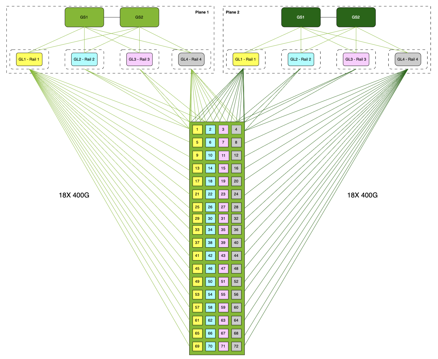
Figure 9 Example diagram of 18-Tray SU connected to 2 planes (4 rails each) of the compute fabric#
The single rack scalable unit provides the following connectivity building blocks:
Within the rack: As shown in Figure 9 all 72 GPUs are interconnected in a single NVLink domain, allowing them to function as a single multi-GPU unit of compute with a bandwidth of 900GB/s (1800 GB/s bi-directional)
For the Compute (East/West) fabric: 18 trays, each with 4 x single-port NVIDIA ConnectX-8 NICs and a total aggregate bandwidth of 3200 Gb/s
For the Converged (North/South) fabric: 18 trays, each with 1x B3240 DPU providing 2x 400Gb/s connections and a total aggregate bandwidth of 800 Gb/s
For the Out-of-band Management fabric, 18 trays, each with 3x 1Gb/s connections providing 54 x 1Gb/s for management
Spine-Leaf Networking#
The network fabrics are built using switches with NVIDIA Spectrum-X Ethernet technology in a full nonblocking fat tree topology to provide the highest level of performance for the application running over the Enterprise RA configuration. The networks are RDMA compliant based fabrics in a leaf-spine architecture where the GPUs are connected using a rail-optimized network topology through their respective SuperNICs. This design allows the most efficient communication for multi-GPU applications within and across the nodes.
The leaf and spine architecture allows for a scalable and reliable network that can fit varied sizes of clusters using the same architecture. The compute network is designed to maximize bandwidth and minimize network latency required to connect GPUs within a server and within a rail.
In addition to the supported compute fabrics the converged spine-leaf network also supports the following attributes:
Provides high bandwidth to high performance storage and connects to the data center network.
Each compute and management node are connected with two 400 Gb/s ports to two separate switches to provide redundancy and high storage throughput.
Out-of-Band (OOB) Management Network#
The OOB management network connects the following components:
Base management controller (BMC) ports of the server nodes
BMC ports of the Bluefield-3 DPU
OOB management ports of switches
This OOB network can also connect other devices that should have management connectivity physically isolated for security purposes. The SN2201 is used to connect to the BMC/OOB 1 Gb/s ports of these components. Scale out this network using a 25 Gb/s or 100 Gb/s spine layer to connect the SN2201 uplink switches.
Optimized Use Case#
This architecture is optimized for both inference and training use cases. Deployment of this single architecture will enable both types of workloads.
Architecture Details#
The components of the Enterprise GB300 NVL72 Enterprise RA using Spectrum-X 800 Gbps for the compute fabric are described in Table 5.
Table 5: GB300 NVL72 Server Ethernet Components with Spectrum-X Fabric
Component |
Technology |
|---|---|
Compute node servers (18) |
Each GB300 NVL Compute Tray is configured with: |
Compute (East/West) Spine-Leaf Fabric |
NVIDIA SN5600 128-port 400 Gb/s switches |
Converged (North/South) Spine-Leaf Fabric |
NVIDIA SN5600 128-port 400 Gb/s switches |
OOB management fabric |
NVIDIA SN2201 48-port 1 Gb plus 4-port 100 Gb/s |
Compute (Node East/West) Fabric Table#
Table 6 below shows the number of cables and switches required for the dual-plane Compute (Node East/West) Fabric for different SU sizes.
Table 6: Compute Node (Node East/West) and Switch Component Count
Compute Counts |
Switch Counts |
Transceiver Counts |
Cable Counts |
|||||||
|---|---|---|---|---|---|---|---|---|---|---|
Nodes |
GPUs |
SUs |
Leaf |
Spine |
Uplinks per leaf to spine @ 400G |
Node to Leaf (Compute) |
Node to Leaf (Switch) |
Switch-to-switch |
Compute-to-Leaf |
Switch-to-switch |
36 |
144 |
2 |
8 |
4 |
18 |
144 |
144 |
288 |
288 |
288 |
72 |
288 |
4 |
16 |
8 |
9 |
288 |
288 |
576 |
576 |
576 |
144 |
576 |
8 |
32 |
12 |
6 |
576 |
576 |
1152 |
1152 |
1152 |
Converged (Node North/South) Fabric Table#
Table 7 below shows the number of cables and switches required for the Converged (Node North/South) Fabric for different SU sizes.
Table 7: Converged (Node North/South) and Switch Component Count
Compute Counts |
Switch Counts |
Converged Network Allocated Ports |
Transceiver Counts |
Cable Counts |
|||||||||||||
|---|---|---|---|---|---|---|---|---|---|---|---|---|---|---|---|---|---|
Nodes |
GPUs |
SUs |
Leaf |
Spine |
CPU (Node N-S) |
Storage |
Mgmt Uplinks |
Customer |
Support |
ISL Ports (both ends) |
Endpoint to Leaf (Node) |
Endpoint to Leaf (Other) |
Endpoint to Leaf (Switch) |
Switch-to-switch |
Node-to-Leaf |
Other-to-Leaf |
Switch-to-switch |
36 |
144 |
2 |
2 |
N/A |
36 |
8 |
4 |
12 |
12 |
30 |
72 |
102 |
58 |
40 |
72 |
40 |
32 |
72 |
288 |
4 |
4 |
2 |
72 |
12 |
4 |
20 |
12 |
256 |
144 |
156 |
100 |
274 |
144 |
52 |
260 |
144 |
576 |
8 |
7 |
4 |
144 |
20 |
8 |
36 |
12 |
448 |
288 |
264 |
184 |
484 |
288 |
78 |
456 |
2 Racks, 36 Trays with 144 Blackwell Ultra GPUs#
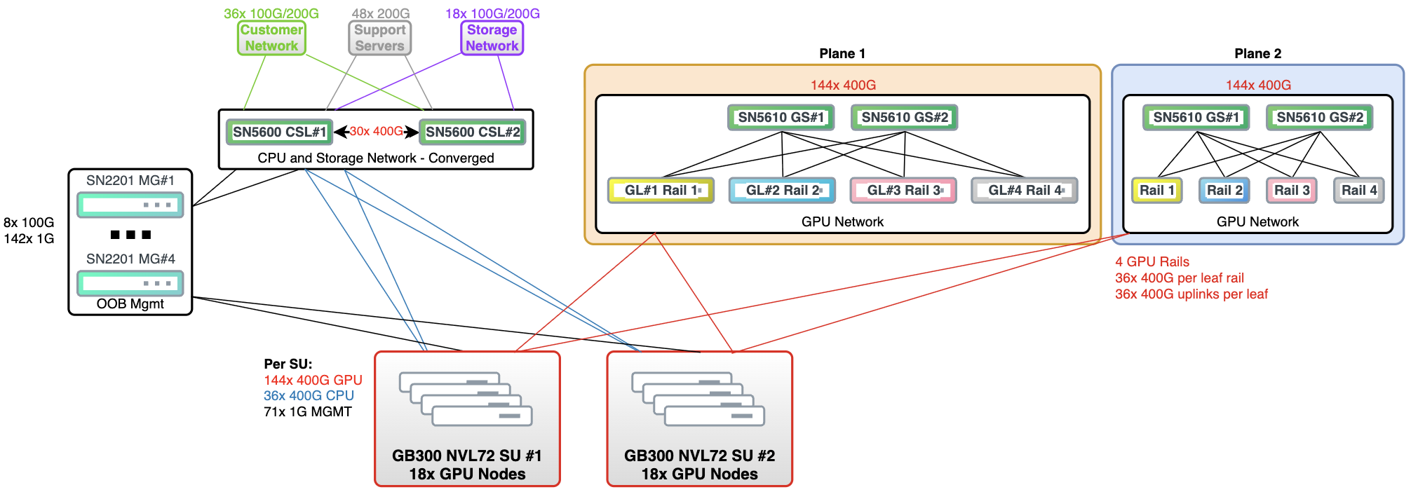
Figure 10 Two Rack GB300 NVL72 with SpectrumX Enterprise RA (144 GPUs)#
Architecture Overview
Two GB300 NVL72 scalable units (SUs) composed of 36 server nodes total (18 nodes per SU)
144 NVIDIA Blackwell GPUs connected through the Spectrum-X compute fabric
Each rack requires 2x SN5600 switches for CPU and storage connectivity and up to 12x SN5600 switches for the dual-plane GPU network
Infrastructure supports scaling from one to two SUs; leaf switches are intentionally underpopulated to align with GB300 NVL72 software design criteria
Network Design
Cost-optimized collapsed spine-leaf architecture for all required fabrics
Spectrum fabric implemented as a rail-optimized, non-blocking 64-port switch design
Port breakout used to consolidate connections without reducing resiliency
Each leaf switch is capable of serving three racks but is configured for two to maintain balance and performance
Connectivity (Under Optimal Conditions)
144x 400G uplinks per SU for GPU Compute traffic
36x 400G uplinks per SU for CPU fabric
Up to 12 support server nodes, quad-connected at 200G
36x 100G/200G connections to the customer network (minimum 25Gb bandwidth per GPU)
18x 100G/200G storage connections (minimum 12.5Gb bandwidth per GPU)
Compute Fabric Design
Dual-plane Spectrum fabric ensures high availability, resiliency, and balanced load distribution
Each plane uses 4 leaf switches, each assigned to the same GPU position across all trays (for example, GPU 1 [Yellow], GPU 2 [Blue], GPU 3 [Pink], GPU 4 [Grey])
Plane 2 mirrors Plane 1 to provide redundancy and throughput stability
ConnectX-8 800Gb ports are split into 2x 400Gb links; each GPU has two 400Gb paths (one to each plane)
Dual-ported optics are recommended to simplify breakout at the ConnectX-8 OSFP port
Management
100Gb/s management fabric with high availability using two 100Gb/s connections per switch to the core network
All nodes connected to 1Gb management switches, which are uplinked into the core management network
VLAN isolation is used to segregate the various north-south and east-west fabrics within the collapsed physical infrastructure
Additional Considerations
Rack layouts are assumed to provide power redundancy within each cabinet; if not available, an alternative rack layout should be considered
Under-populated port strategy and breakout usage preserve headroom for future scalability while maintaining operational resilience
4 Racks, 72 Trays with 288 Blackwell Ultra GPUs#
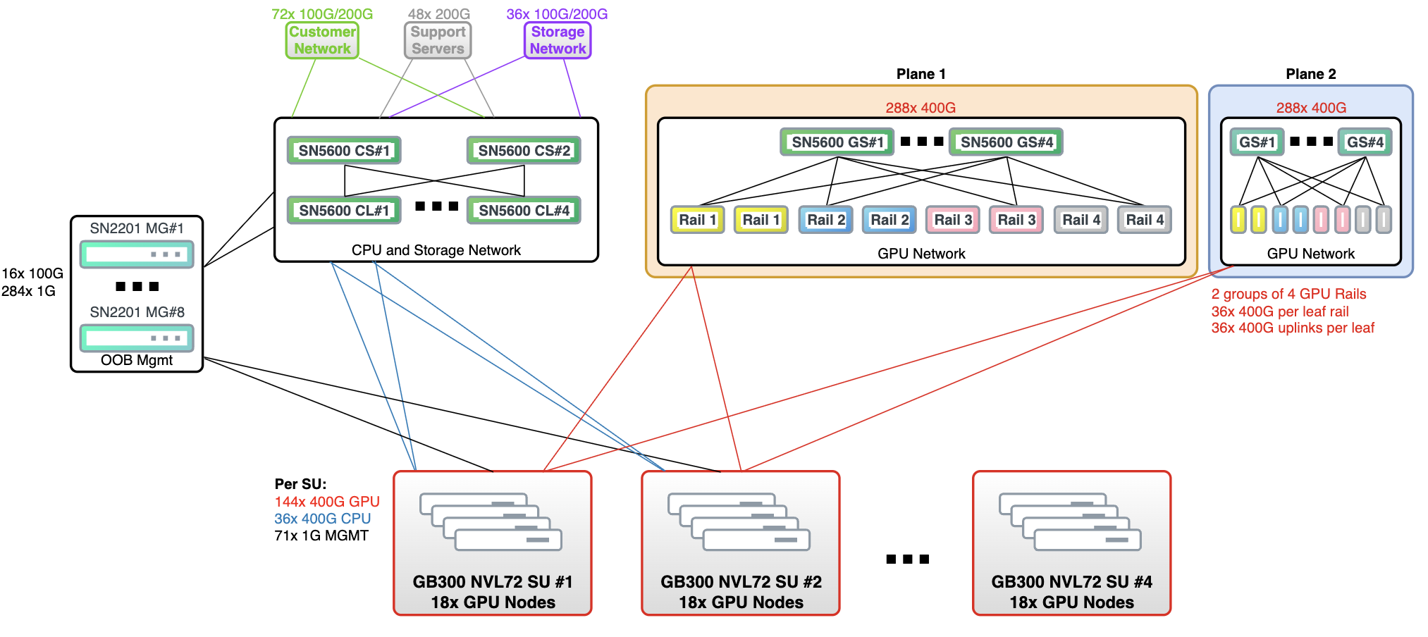
Figure 11 Four Rack GB300 NVL72 with Spectrum-X Enterprise RA (288 GPUs)#
Architecture Overview
Four GB300 NVL72 scalable units (SUs) with 72 trays/nodes and 288 Blackwell Ultra GPUs interconnected via the Spectrum-X compute fabric
Networking sized to scale between three and four SUs while keeping a consistent per-SU node count of 18 trays
Design references switch, transceiver, and cable requirements as summarized in the associated bill-of-materials tables (Table 6 and Table 7)
Network Design
Cost-efficient collapsed spine-leaf architecture for all fabrics except the GPU Compute (E-W) network
GPU Compute (E-W) fabric implemented as a separate, isolated leaf-spine network to deliver high-bandwidth, low-latency node-to-node communication
Port breakout used wherever possible to consolidate ports without compromising resiliency
Leaf switches can support up to three racks but are intentionally underpopulated to serve only two racks to satisfy GB300 NVL72 software requirements
Connectivity (Under Optimal Conditions)
144x 400G uplinks per SU for GPU Compute traffic
36x 400G uplinks per SU for CPU traffic
Up to 12 support server nodes, all quad-connected at 200Gb
72x 100G/200G connections toward the customer network (minimum 25Gb bandwidth per GPU)
36x 100G/200G storage connections (minimum 12.5Gb bandwidth per GPU)
Compute Fabric Design
Spectrum compute fabric for the Node E-W network is rail-optimized and non-blocking using 64-port switches in a full spine-leaf topology
Dual-plane Spectrum fabric provides high availability, resiliency, and load-balancing for GPU traffic
Each plane has 4 leaf switches; each leaf is wired to the same GPU position across all trays (for example, GPU 1 [Yellow], GPU 2 [Blue], GPU 3 [Pink], GPU 4 [Grey])
Plane 2 mirrors Plane 1, and each ConnectX-8 800Gb port is broken out into 2x 400Gb links so each GPU has a dedicated 400Gb connection to each plane
Dual-ported optics at the ConnectX-8 OSFP port are recommended to simplify breakout, as detailed in NVIDIA’s optical module documentation
Management
100Gb/s management fabric with high availability using two 100Gb/s connections per management switch to the core network
All nodes connect to 1Gb management switches, which are then uplinked into the core network
Per-SU management uses two SN2201 switches; in a four-rack design this yields eight SN2201 switches, each uplinked to the core via 2x 100G links
Additional Considerations
VLAN isolation is applied across the converged Node North-South network fabrics that share the underlying physical infrastructure
Rack layout is assumed to provide power supply redundancy within each rack; if this cannot be met, an alternative rack layout should be considered
8 Racks, 144 Trays with 576 Blackwell Ultra GPUs#
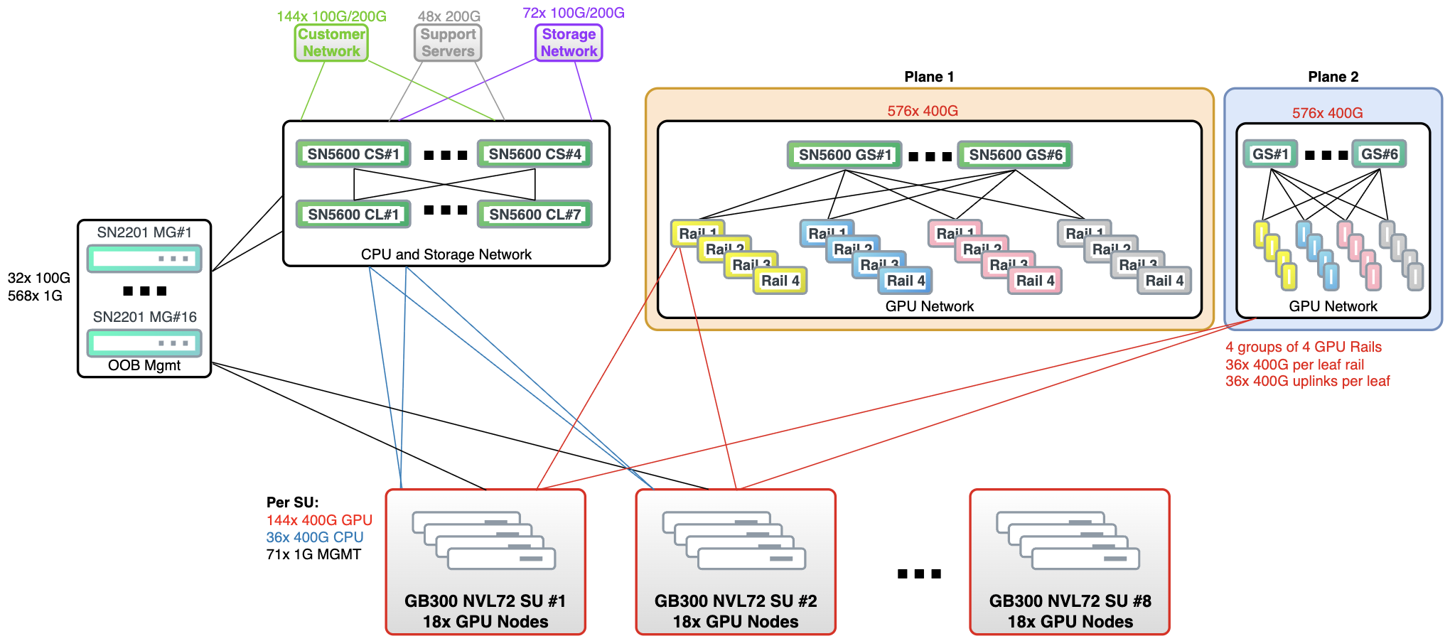
Figure 12 Eight Rack GB300 NVL72 with Spectrum-X Enterprise RA (576 GPUs)#
Architecture Overview
Eight GB300 NVL72 scalable units (SUs) with 144 trays/nodes and 576 Blackwell GPUs interconnected via Spectrum-X compute fabric.
Networking sized to scale between seven and eight SUs while keeping 18 trays per SU.
Switch, transceiver, and cable requirements are defined in the associated bill-of-materials tables (Table 6 and Table 7).
Network Design
Cost-efficient spine-leaf architecture for all fabrics except the GPU Compute (E-W) fabric.
GPU Compute (E-W) network implemented as a separate, isolated leaf-spine fabric to deliver high-bandwidth, low-latency node-to-node communication.
For very large deployments (around 1024 nodes and above), a super-spine layer is introduced to maintain non-blocking point-to-point connectivity.
Port breakout is used wherever possible to consolidate ports while preserving resiliency.
Each leaf switch can support up to three racks but is intentionally underpopulated to serve only two racks to meet GB300 NVL72 software requirements.
Connectivity (Under Optimal Conditions)
144x 400G uplinks per SU for GPU Compute traffic.
36x 400G uplinks per SU for CPU traffic.
Up to 12 support server nodes, all quad-connected at 200Gb.
144x 100G/200G connections toward the customer network (minimum 25Gb bandwidth per GPU).
72x 100G/200G storage connections (minimum 12.5Gb bandwidth per GPU).
Compute Fabric Design
Spectrum fabric for the Node E-W network is rail-optimized and non-blocking using 64-port switches in a full super-spine–spine-leaf topology.
Dual-plane Spectrum fabric provides high availability, resiliency, and load-balancing for GPU traffic.
Each plane uses 4 leaf switches; each leaf is wired to the same GPU position across all trays (for example, GPU 1 [Yellow], GPU 2 [Blue], GPU 3 [Pink], GPU 4 [Grey]).
Plane 2 mirrors Plane 1, and each ConnectX-8 800Gb port is broken out into 2x 400Gb connections, so each GPU has a dedicated 400Gb link to each plane.
NVIDIA recommends using a dual-ported optic at the ConnectX-8 OSFP port to simplify breakout, as described in the referenced optic documentation.
Management
100Gb/s management fabric with high availability using two 100Gb/s connections per management switch to the core network.
All nodes are connected to 1Gb management switches, which are then uplinked into the core network.
Per-SU management uses two SN2201 switches; in an eight-rack design this yields 16 SN2201 switches, each uplinked to the core via 2x 100G links.
Additional Considerations
VLAN isolation is used across the converged North-South network fabrics that share the underlying physical infrastructure.
Rack layout is assumed to provide power supply redundancy within each rack; if this is not available, an alternative rack layout should be considered.