

Installation#
This section provides a step-by-step process to successfully install Kubernetes via BCM on a standard cluster based off the Enterprise RA Software BOM.
Log into BCM headnode as root.

Figure 1 Running cm-kubernetes-setup on the BCM head node, connecting to CMDaemon#
Use cmsh > device > list to confirm the nodes you want deployed (can be various).
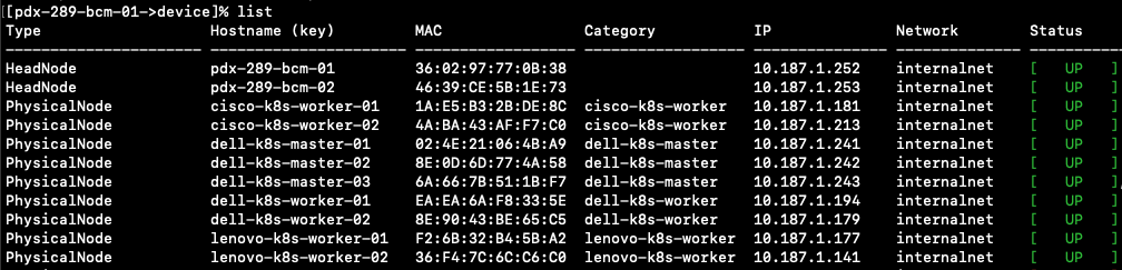
Figure 2 Output of the cmsh device list showing the head nodes and master/worker nodes#
Run the
cm-kubernetes-setupcommand.root@pdx-289-bcm-01:# cm-kubernetes-setupWizard screen.
a. Select Deploy, and click OK.
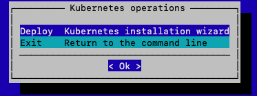
Figure 3 Kubernetes operations wizard menu with the Deploy option#
Choose a target Kubernetes Version.
a. Use the space key to check selected version.
b. Click OK.
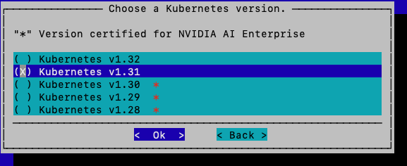
Figure 4 Kubernetes version selection screen#
Note
According to the Enterprise RA Software BOM, we select Kubernetes v1.31. The version may differ for your specific deployment. See Appendix A.
Type in docker registry mirror server address if needed (optional).
a. This part can be skipped by clicking OK.

Figure 5 Docker registry mirror server address entry screen#
Give a cluster name, domain name, external FQDN and desired IP addresses.
a. Type in all information required, then click OK.
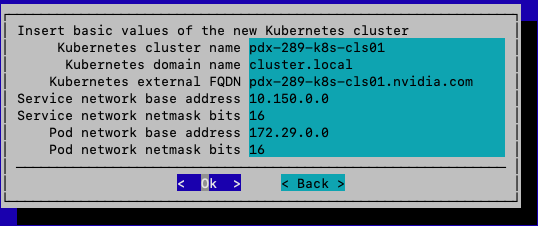
Figure 6 Cluster name, domain name, external FQDN, and IP address configuration screen#
Expose Kubernetes API server to external network if needed.
a. Select yes, and click OK.
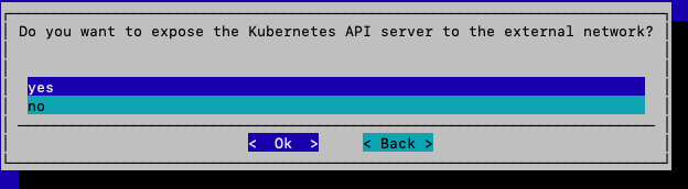
Figure 7 Expose Kubernetes API server to external network selection screen#
Select preferred internal network used by Kubernetes nodes.
a. Choose internalnet, and click OK.
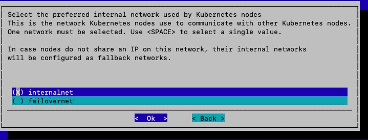
Figure 8 Internal network selection screen with internalnet chosen#
Selecting master nodes.
a. Use space key to toggle master nodes that are already deployed.
b. Click OK.
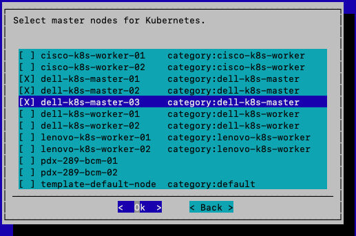
Figure 9 Master node selection screen#
Choosing Kubernetes workers categories.
a. Choose the category that was previously configured (Prerequisites).
b. Toggle with space key, then click OK.
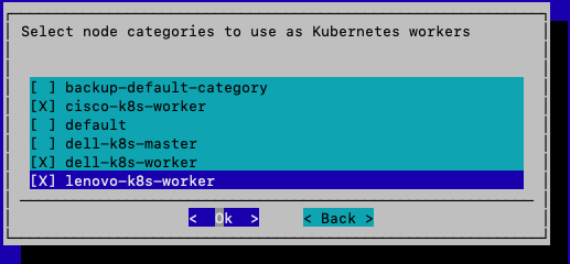
Figure 10 Kubernetes worker categories selection screen#
Choosing specific nodes if there are any.
a. Any specific node included in the worker category can be chosen. In this case, none are available.
b. Click OK.
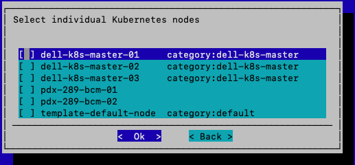
Figure 11 Specific node selection screen#
Choosing Etcd nodes.
a. Toggle all three master nodes as Etcd nodes.
b. Click OK.
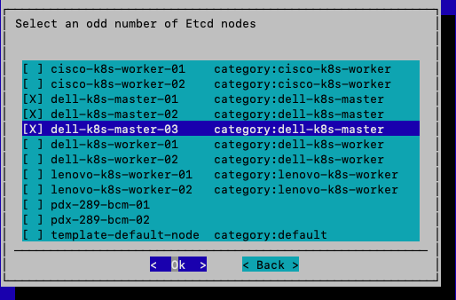
Figure 12 Etcd node selection screen with three master nodes toggled#
Note
etcd is the distributed key-value database that stores all Kubernetes cluster state (pods, services, secrets, configs).
For Small/medium cluster (≤ 200 worker nodes):
Just let etcd run on the control plane nodes (usually 3).
Each control plane node runs both kube-apiserver and etcd.
For Larger cluster (≥ 200+ worker nodes):
Create 3–5 dedicated etcd nodes.
Deploy 3 or 5 separate nodes only running etcd.
Configuring API Server ports.
a. There is only one API server in this case.
b. Use default ports assigned, click OK.
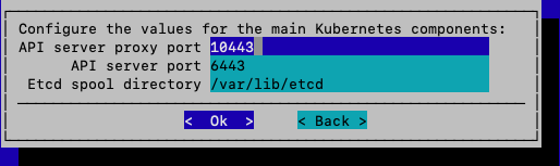
Figure 13 API server port configuration screen showing default ports#
Note
If there are multiple Kubernetes clusters, please assign a unique port number for each API server.
Choosing CNI (Container Network Interface) plugins.
a. Toggle recommended Calico as CNI, click OK.
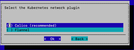
Figure 14 CNI plugin selection screen with Calico selected#
Note
Kubernetes itself doesn’t handle pod networking directly — instead it relies on CNI plugins to set up networking for pods and services.
A CNI plugin is responsible for:
Assigning IP addresses to pods
Setting up routes so pods can talk to each other across nodes
Enforcing network policies (firewalls, isolation, etc.)
Installing Kyverno policy engine.
a. Select yes, and click OK.
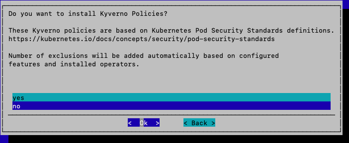
Figure 15 Kyverno policy engine installation screen with yes selected#
Note
Kyverno is a Kubernetes-native policy engine. It enables policy-as-code using YAML, avoiding the need for new languages.
Installing Kyverno policies.
a. This will be configured later, choose no, and click OK.
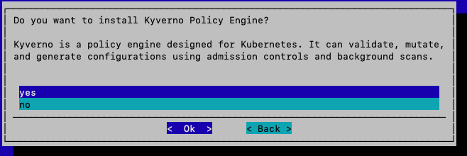
Figure 16 Kyverno policies installation screen with no selected#
Note
The base installation can be performed without policy initialization, with policy Custom Resource Definitions (CRD) applied subsequently through standard Kubernetes workflows.
Choosing the operators to install.
As per the Enterprise RA Software BOM, we install following operators:
NVIDIA GPU Operator
Kubernetes Dashboard
Kubernetes Metric Server
Kubernetes State Metrics
MetalLB
Network Operator
NIM Operator
Prometheus Adapter
Prometheus Operator Stack
a. Toggle selected Operators by Space key.
b. Click OK.
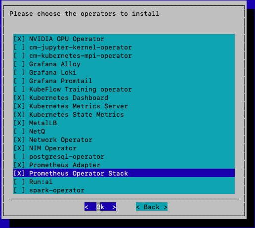
Figure 17 Operator selection screen with all required operators toggled#
Choosing NVIDIA GPU Operator version.
According to the Enterprise RA Software BOM, we chose v24.9.2.
a. Toggle v24.9.2, and click OK.
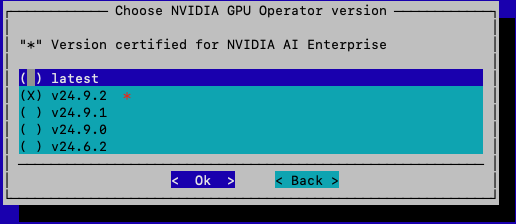
Figure 18 GPU Operator version selection screen with v24.9.2 selected#
Choosing Network Operator version.
According to the Enterprise RA Software BOM, version v25.1.0 is selected.
a. Toggle v25.1.0, and click OK.
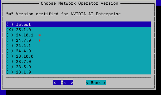
Figure 19 Network Operator version selection screen with v25.1.0 selected#
Customizing YAML file for GPU Operator.
If a custom YAML file is available, this is where the value can be passed to the Helm chart. In this case, standard configuration parameters are used.
a. Leave it empty, and click OK.
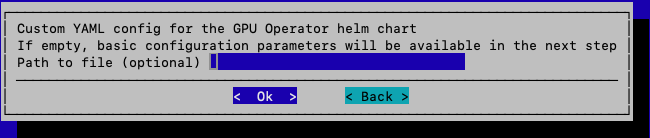
Figure 20 Custom YAML file entry screen for GPU Operator (left empty)#
Configuring NVIDIA GPU Operator.
In this case, direct access to the GPU is not required. Only discovering is needed.
a. Toggle nfd.enabled.
b. Click OK.
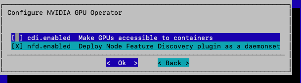
Figure 21 GPU Operator configuration screen with nfd.enabled toggled#
Note
In the special case that direct access to GPU is needed (e.g., upgrading GPU firmware), then
cdineeds to be toggled.Customizing YAML file for Network Operator.
If a custom YAML file is available, this is where the value can be passed to the Helm chart. In this case, standard configuration parameters are used.
a. Leave it empty, and click OK.
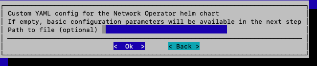
Figure 22 Custom YAML file entry screen for Network Operator (left empty)#
Configuring Network Operator.
Both options need to be enabled: network discovery is required, and SR-IOV is necessary to perform RDMA and related functions.
a. Toggle both, and click OK.
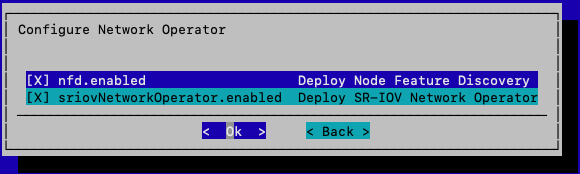
Figure 23 Network Operator configuration screen with both options enabled#
Creating a MetalLB IP address Pool.
a. Click Add, and click OK.
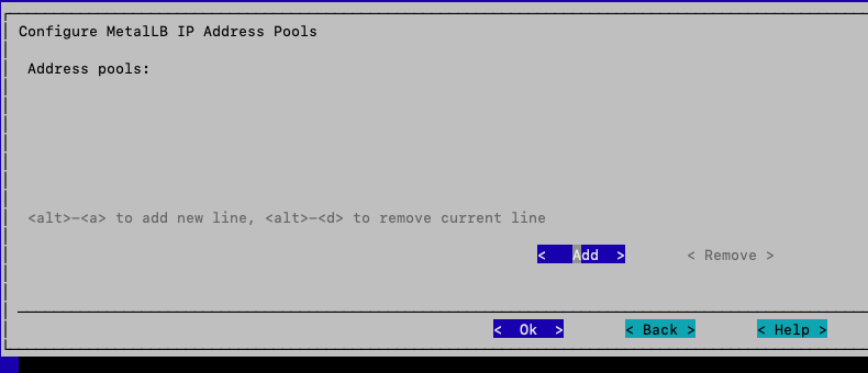
Figure 24 MetalLB IP address pool creation screen with Add selected#
Note
MetalLB is a load-balancer implementation for bare-metal Kubernetes clusters.
In cloud environments (AWS, GCP, Azure), Kubernetes Services of type LoadBalancer automatically fetch a cloud provider’s load balancer. On bare-metal or self-hosted clusters, there’s no built-in load balancer. That’s where MetalLB comes in — it provides a way to assign external IPs to services and handle traffic routing.
Key Features:
Implements Service type LoadBalancer — exposes a Service to the outside world with an external IP.
Two operating modes:
ARP / Layer 2 mode — Simple: one node advertises the external IP using ARP/NDP. Easy to set up but doesn’t support advanced routing.
BGP mode (Layer 3) — MetalLB peers with the network routers using BGP. Scales better, provides true load balancing across nodes, integrates into enterprise networks.
Supports address pools — it is possible to configure IP ranges (like
192.168.1.240-192.168.1.250) that MetalLB assigns to Services.Works with standard Kubernetes resources — no need for special CRDs for basic use; it extends existing Service semantics.
Configuring MetalLB IP address pool.
a. Type in a name for the IP address pool.
b. Type in an IP range that was reserved for MetalLB.
c. Click OK.
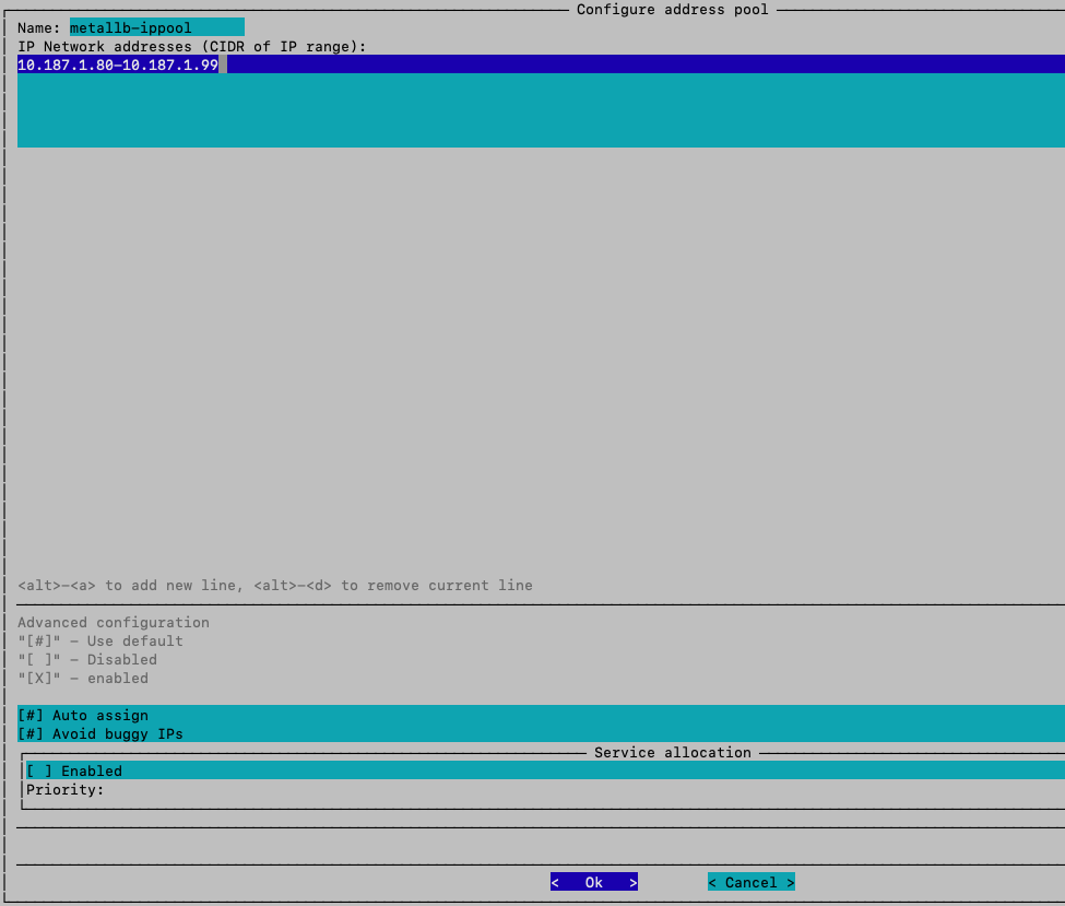
Figure 25 MetalLB IP address pool configuration screen showing name and IP range fields#
Confirming the IP address pool created.
a. The name of IP address pool should appear here and click OK.
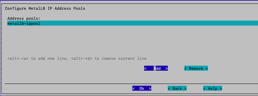
Figure 26 IP address pool confirmation screen showing the newly created pool#
Creating MetalLB L2 advertisements.
a. Click Add, and click OK.
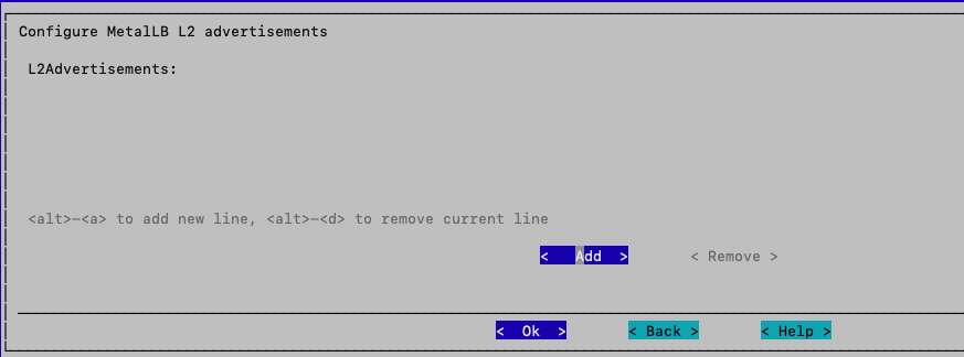
Figure 27 MetalLB L2 advertisement creation screen with Add selected#
Note
An L2Advertisement is not typically required in this scenario. If a dedicated service network is being used, then L2Advertisement becomes necessary. In this case, since both the Kubernetes control plane and the services are running on the same network, explicit advertisement is not required. However, it is being configured as a best practice.
Configuring MetalLB L2 advertisements.
a. Type in a name for L2 advertisements.
b. Toggle the IP address pool that was previously created, and click OK.
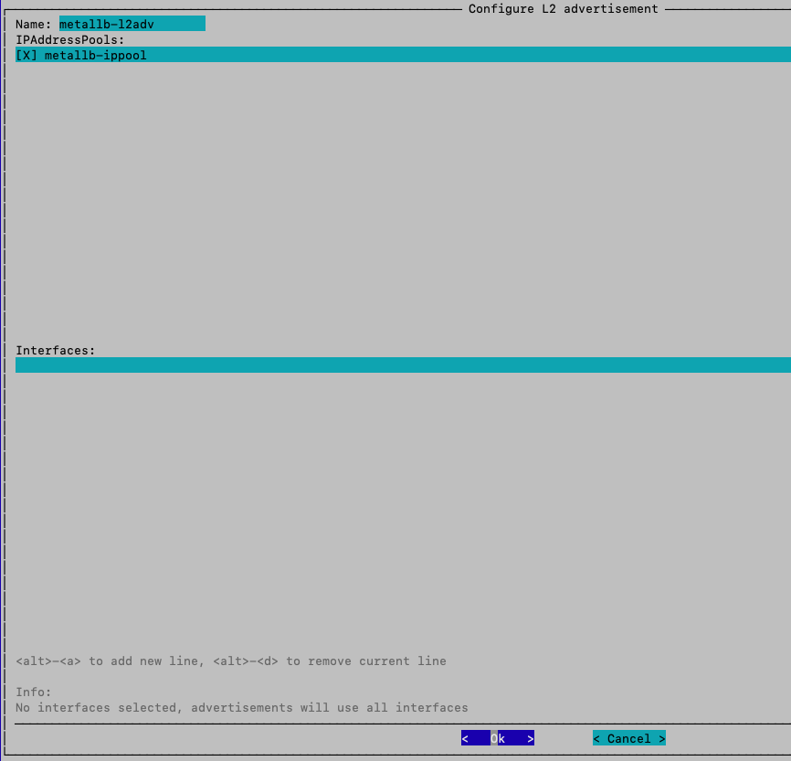
Figure 28 MetalLB L2 advertisement configuration screen with name and IP address pool selected#
Confirming the L2 advertisements.
a. The name of L2 advertisements should appear, and click OK.
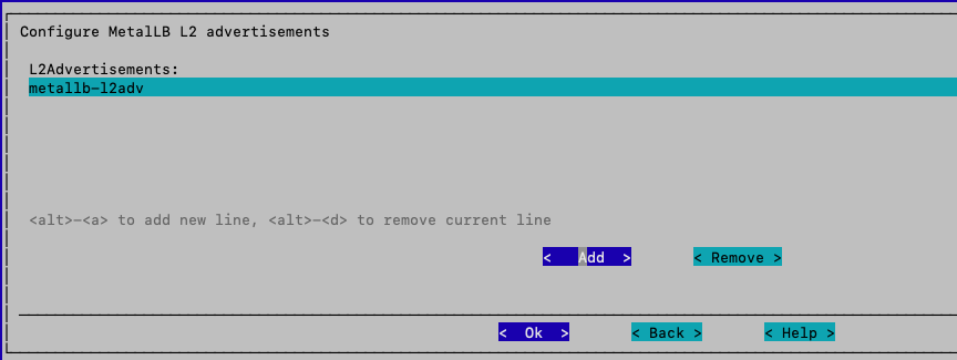
Figure 29 L2 advertisement confirmation screen showing the newly created advertisement#
Installing Ingress Controller.
Instead of directly exposing NGINX via Service, use Ingress resources with the NGINX Ingress Controller for routing multiple apps behind one IP/hostname.
a. Toggle it, and click OK.
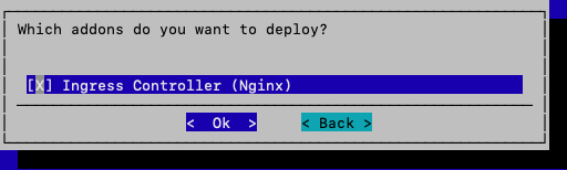
Figure 30 Ingress Controller installation screen with NGINX Ingress Controller toggled#
Note
NGINX Service = exposes NGINX pods internally/externally.
NGINX Ingress Controller = smart entrypoint that routes multiple domains/paths to different services.
In production environment, it is best to almost always use Ingress instead of exposing each Service separately.
Exposing Kubernetes Ingress to default HTTPS port
a. Choose yes, and click OK.
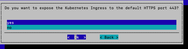
Figure 31 Expose Kubernetes Ingress to default HTTPS port selection screen#
Configuring Ingress port for Kubernetes Cluster.
a. Keep default values, and click OK.
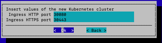
Figure 32 Ingress port configuration screen showing default port values#
Installing BCM NVIDIA Packages.
Not all packages are needed. However, container-toolkit runtime is required for the GPU (worker) nodes.
a. Choose yes, and click OK.
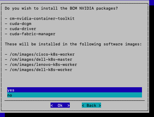
Figure 33 BCM NVIDIA Packages installation screen with yes selected#
Note
On newer versions of BCM (BCM 11.x), it is possible to pick and choose packages individually.
Installing Permission Manager.
This is necessary for creating users, managing users, groups, and ServiceAccounts. It is also useful for shared clusters among multiple teams.
a. Choose yes, and click OK.
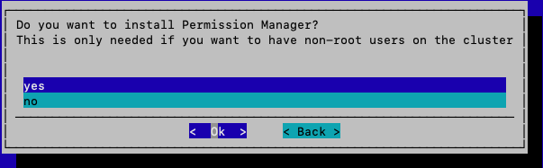
Figure 34 Permission Manager installation screen with yes selected#
Configuring Kubernetes StorageClass.
In this case, there aren’t any other StorageClass on the local path.
a. Toggle local path, and click OK.
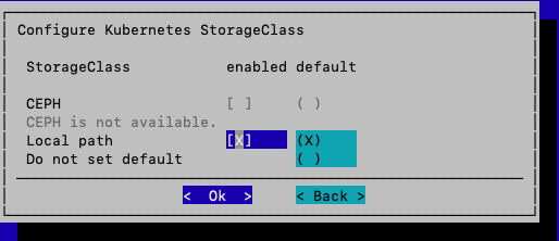
Figure 35 Kubernetes StorageClass configuration screen with local path selected#
Configuring local path storage pool for Kubernetes.
In this case, use default value.
a. Click OK.

Figure 36 Local path storage pool configuration screen with default value#
Summary.
a. Toggle Save config & deploy.
b. Click OK.
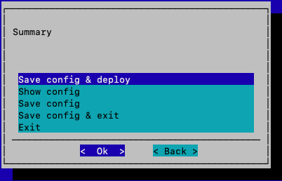
Figure 37 Summary screen with Save config & deploy toggled#
Saving the config file.
A
.conffile will be saved into the root folder.a. Name the config file.
b. Click OK.
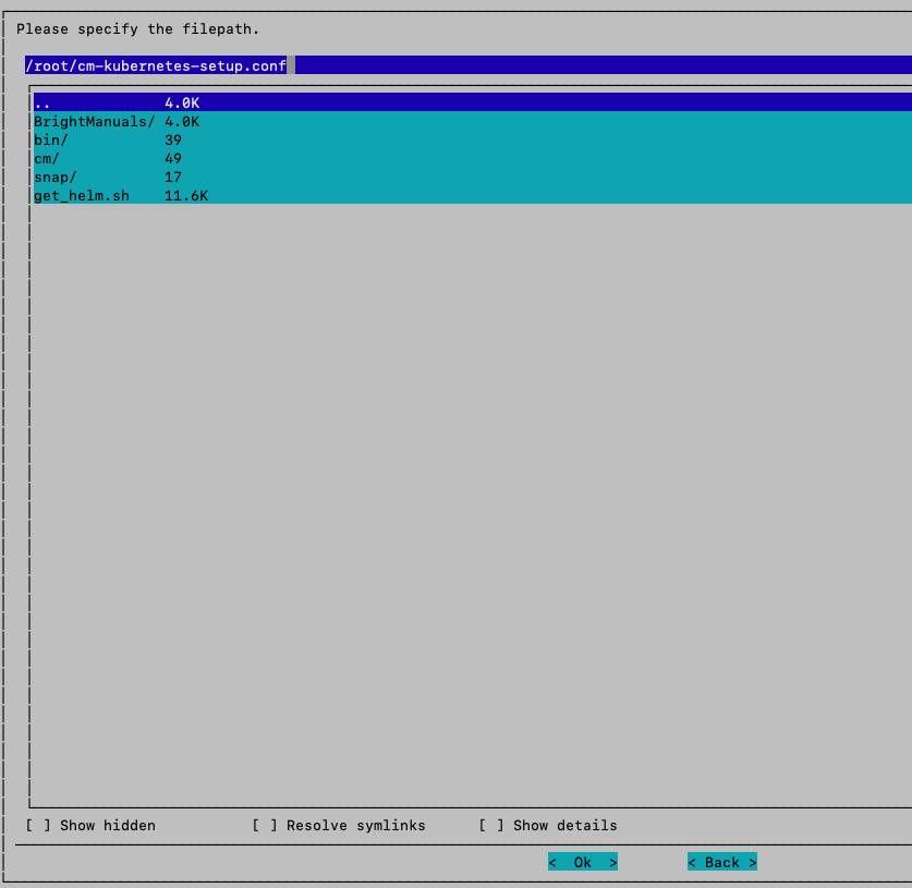
Figure 38 Config file naming screen#
Rebooting.
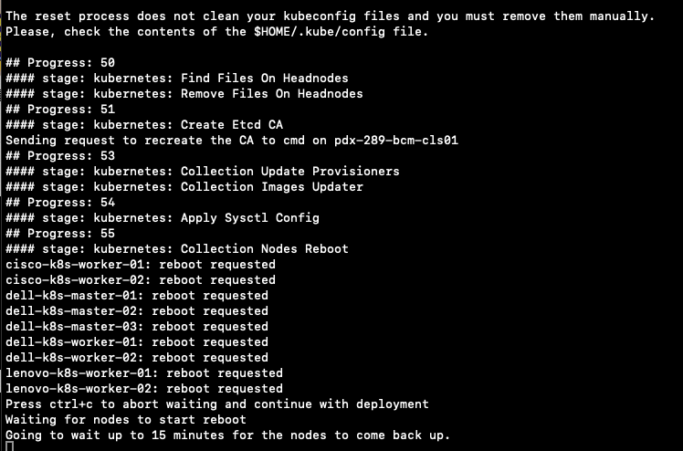
Figure 39 Deployment progress screen showing nodes being rebooted#
All master nodes and worker nodes will be deployed and rebooted automatically.
Note
If there is an error during deployment, a command line will pop up and ask what to do. Try Retry r first, sometimes it’s just a connection issue to pull the packages, if it doesn’t resolve it, enter d for Debugging to see where the issue is.

Figure 40 The deployment error prompt showing the Undo/Abort/Skip/Retry/Info/Debug/Remote debug options#
Deploying MetalLB Load Balancer service.
The
cm-kubernetes-setupwizard sets up the Ingress Controller to operate as a NodePort service. After deployment, deploy a MetalLB LoadBalancer service to make the Ingress Controller accessible externally. This assigns an external IP address, enabling traffic from outside the Kubernetes cluster to reach the Controller.a. Log in BCM head node.
b. Type in
cmsh.c. Inside cmsh, type in
kubernetes, thenappgroups.d. Inside appgroups, type in
use system.e. Inside system, type in
applications.f. Inside applications, type in
use ingress_controller.g. Inside ingress_controller, type in
set config.h. Looking for section of port type:
NodePort, change it toLoadBalancer.i. Save the changes, commit and quit.

Figure 41 cmsh sequence for deploying MetalLB LoadBalancer service#
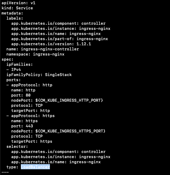
Figure 42 The ingress-nginx-controller service config with the port type set to LoadBalancer#
To verify changes, the ingress controller nginx service external-IP will change from “none” to the first IP address that was previously set in the MetalLB address pool. The pod IP address will change from internal IP to external IP.
j. Type
kubectl get svc -n ingress-nginxto check ingress controller nginx service.
Figure 43 Output of kubectl get svc -n ingress-nginx showing the external IP assigned#
k. Or type
kubectl get ingress -Ato check pod IP address.
Figure 44 Output of kubectl get ingress -A showing the ingress resources and addresses#