

Getting Started#
What You’ll Need#
Essential Hardware Components#
HSB Development Kit - Lattice CPNX100-ETH-SENSOR-BRIDGE
Camera - HSB supported sensors include Leopard Imaging VB1940 Eagle Camera, Leopard Imaging IMX274
Photodetector - Silicon photodiode with broad spectrum response (400-1000nm) and high-frequency response (>1MHz)
LED - High-brightness white LED (12,000-14,000 mcd, 20mA, 3.0-3.2V) for visual timing reference
Hardware Component Schematics#
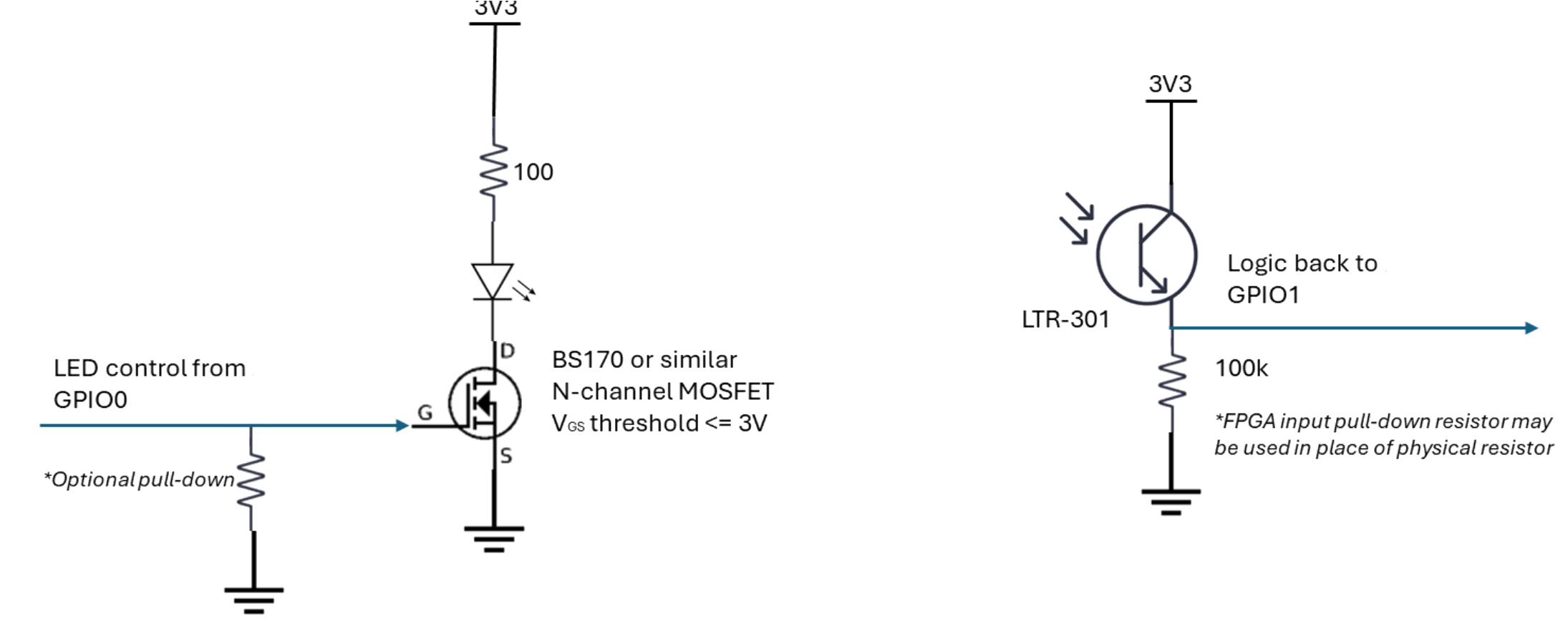
LED and Photodetector Circuit Configuration
HSB GPIO Connections
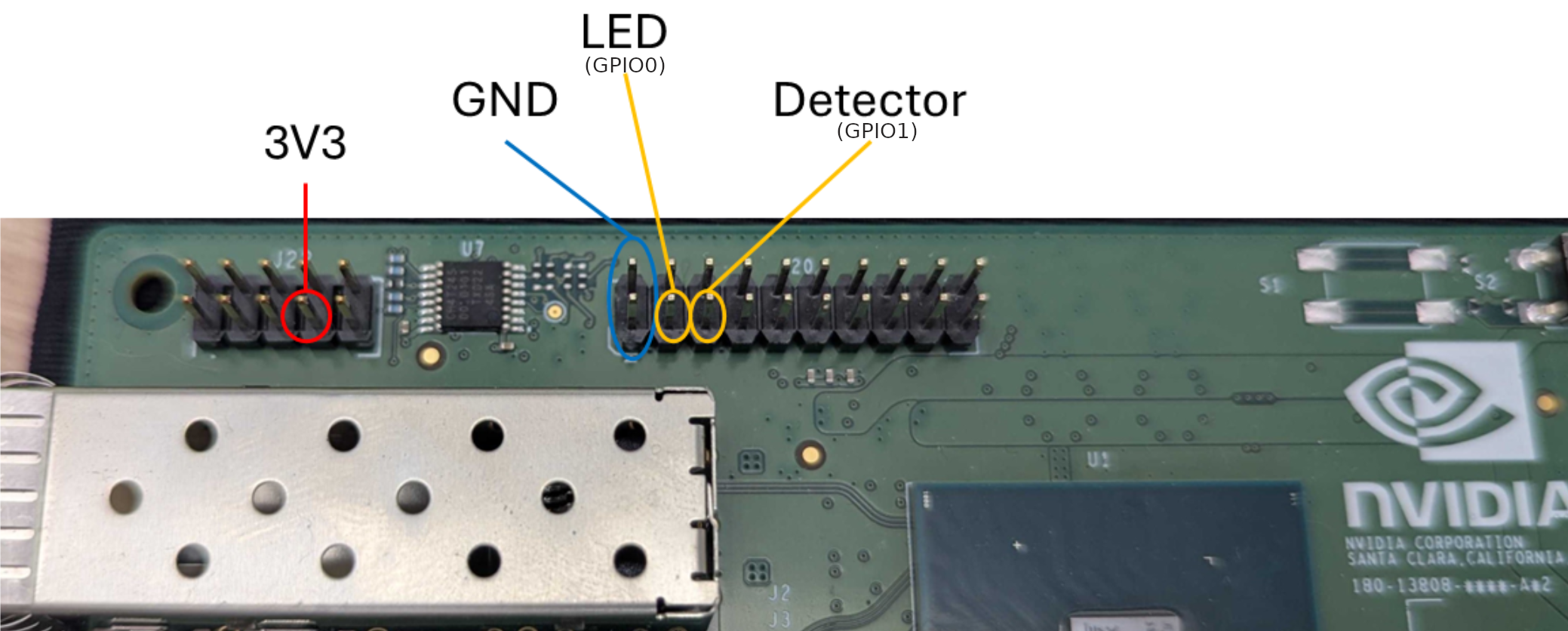
The schematics provide the essential wiring diagrams for setting up the HSB Native Latency Measurement Tool. Please review these diagrams carefully before assembling your hardware setup to ensure proper connections and avoid potential damage to components.
Each schematic shows the specific pin assignments, voltage levels, and connection requirements for the measurement system components.
Bill of Materials (BOM)
Refer to the Bill of Materials (BOM) - LED/Photodetector Circuit for the complete list of components and their specifications.
Camera-to-Display Setup Diagram#
The diagram below shows the complete system configuration for HSB Native Latency measurement. Use this as your reference guide when connecting all components together to ensure proper signal flow and timing synchronization throughout the measurement pipeline.
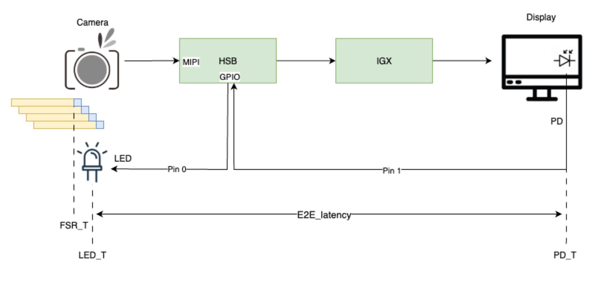
Complete system overview showing camera, HSB, host system, and measurement components
Key Timing Events#
The diagram illustrates three critical timestamps that enable precise latency measurement:
FSR_T (Frame Start Received) - Timestamp when the camera frame start signal is received at the HSB FPGA, triggering the LED activation sequence
LED_T (LED Triggered) - Timestamp when the LED_ON event occurs at GPIO pin 0, marking the visual reference point
PD_T (Photodetector Triggered) - Timestamp when the PD_TRIGGERED event is detected, indicating the LED signal has been captured from the display
The camera-to-display latency is calculated as: Latency = PD_T - LED_T
Rolling Shutter vs Global Shutter Considerations#
Shutter Type Differences#
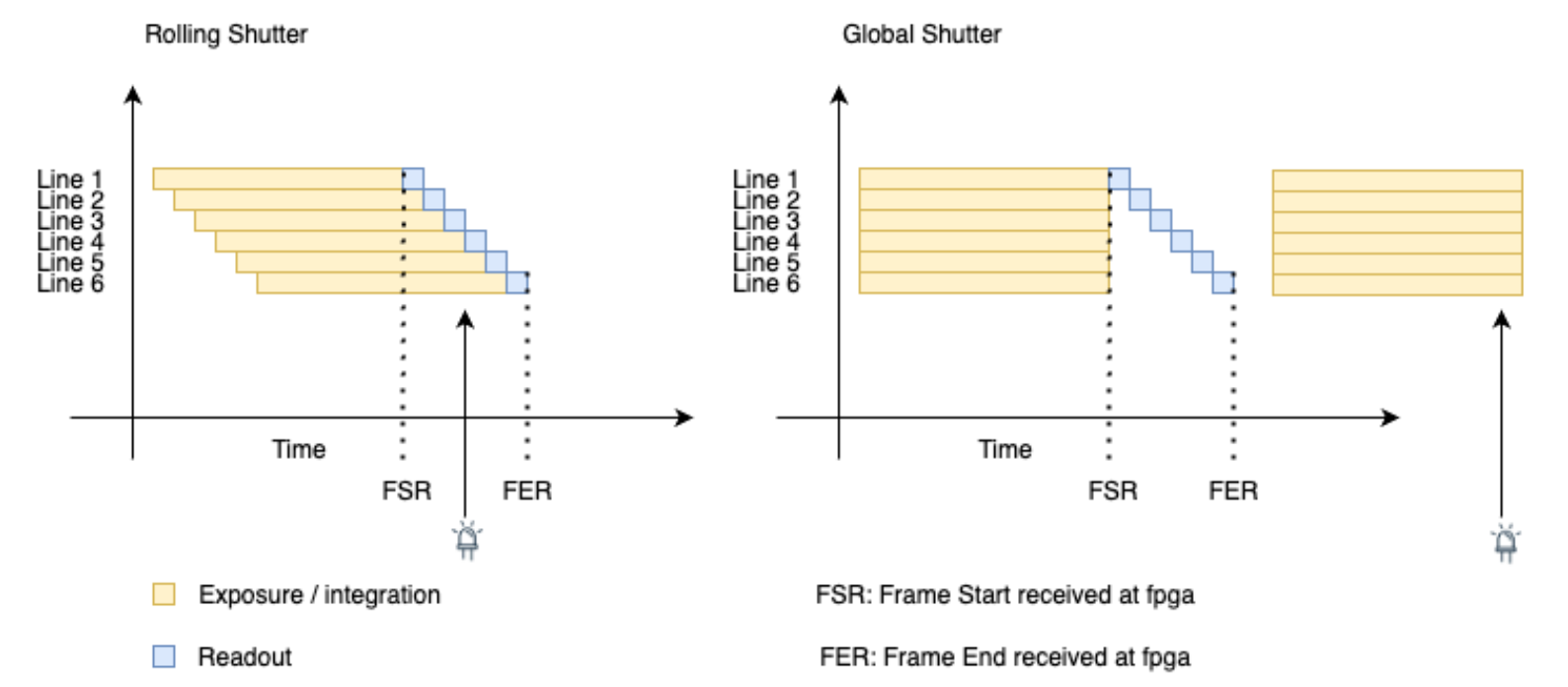
Understanding your camera’s shutter type is crucial for accurate latency measurement, as each type requires different timing strategies and has distinct latency characteristics.
Rolling Shutter Behavior#
Capture Process:
Pixels are captured row-by-row sequentially
Each row has a different capture timestamp
Frame readout occurs over time (typically 16-33ms)
Latency Implications:
Variable Latency: Different rows have different capture times
Jitter Source: Row-to-row timing variations contribute to measurement uncertainty
Measurement Challenge: Need to account for exposure timing across the frame
Software Event Setup:
FSR Event Timing: FSR event triggers LED activation during frame readout
Readout Time Window: LED can be captured in the current frame being read
Timing Strategy: LED activated during the frame readout period
Current Frame Capture: LED light appears in the same frame as the trigger event
Global Shutter Behavior#
Capture Process:
All pixels captured simultaneously at a single moment
Uniform exposure timing across entire frame
Readout occurs after capture is complete
Latency Implications:
Consistent Latency: All pixels captured at the same time point
Reduced Jitter: Uniform timing across the entire frame
Simpler Measurement: Single, well-defined capture time point
Software Event Setup:
FSR Event Timing: FSR event occurs after frame capture is complete
No Current Frame Window: Frame already captured when FSR is received
Next Frame Strategy: LED must be delayed for the next frame
Delayed Capture: LED light appears in the subsequent frame
Setup Configuration Differences#
The key difference between shutter types is the LED trigger delay configuration:
Rolling Shutter Configuration#
In Rolling shutter, the LED triggers on the current frame - the LED can be captured within the same frame that generated the FSR event.
# Rolling shutter - immediate LED trigger
# No delay, LED triggers during frame readout
led_trigger_delay = 0
Global Shutter Configuration#
In Global shutter, the LED triggers for the next frame - we must wait for the subsequent frame since the current frame capture is already complete when FSR is received
# Global shutter - delayed LED trigger based on sensor readout time
# Delay based on specific sensor mode readout timing
led_trigger_delay = sensor_readout_time
Important: The LED trigger delay for global shutter cameras must be configured based on the specific sensor mode’s readout time to ensure proper next-frame synchronization.
Timing Sequence Diagrams#
Rolling Shutter Sequence#
The following sequence diagram illustrates the timing flow for rolling shutter cameras, showing how events are synchronized within the current frame:
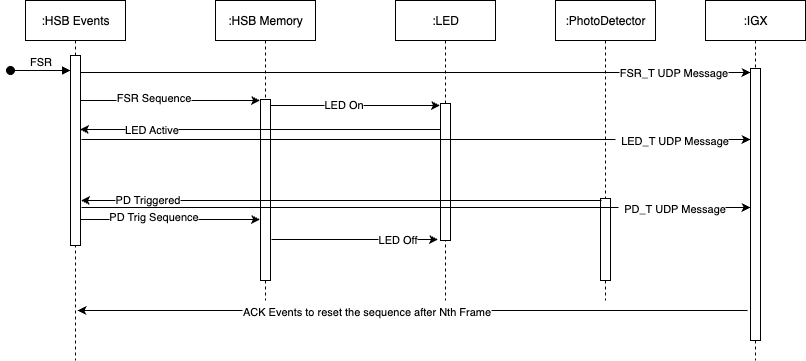
Event Sequence:
Frame Start - Camera begins row-by-row capture
FSR_T - HSB FPGA receives frame start signal
LED_T - LED immediately triggers (delay = 0) during frame readout
Frame Processing - Current frame continues through pipeline
Display Output - Frame appears on display with LED visible
PD_T - Photodetector captures LED from display
Key Timing Characteristics:
LED activation occurs during the current frame readout period
Zero delay between FSR and LED trigger
LED appears in the same frame that generated the FSR event
Latency calculation: PD_T - LED_T
System Requirements#
Supported Platforms#
NVIDIA Jetson AGX Orin
NVIDIA Jetson IGX Orin with NVIDIA RTX A6000 dGPU (used for testing and performance results)
Software Requirements#
NVIDIA Jetson AGX Orin: JetPack 6.2 or later with Ubuntu 22.04 - Verify with
lsb_release -aNVIDIA IGX Orin: IGX Software (BaseOS) 1.1.2 or later - IGX Orin does not use JetPack; refer to the IGX Software documentation for setup
Holoscan Sensor Bridge Software - Clone from GitHub:
git clone https://github.com/nvidia-holoscan/holoscan-sensor-bridge
Camera Compatibility#
The HSB Native Latency Measurement Tool works with all sensors supported by the Holoscan Sensor Bridge. Example applications are included for the following sensors:
Leopard Imaging VB1940 Eagle - Global shutter camera. See the VB1940 section in the HSB User Guide for setup and configuration details.
Leopard Imaging IMX274 - Rolling shutter camera. See the IMX274 section in the HSB User Guide for setup and configuration details.