Flashing and Booting the Target Device
Use the flash.sh helper script to flash the board with the bootloader and kernel, and optionally, flash the root file system to internal or an external storage device.
Use the script l4t_initrd_flash.sh to flash internal or external media connected to a Jetson device. This script uses the recovery initial ramdisk to do the flashing, and can flash external and internal media with the same procedure. Since this script uses kernel for flashing, it is generally faster than flash.sh. See the section Flashing with initrd for more details.
Before You Begin
The following directories must be present:
• bootloader: Bootloader plus flashing tools, such as TegraFlash, CFG, BCT, etc.
• kernel: A kernel Image /vmlinux.uimg, DTB files, and kernel modules
• rootfs: The root file system that you download
This directory starts empty. You populate it with the sample file system.
• nv_tegra: User space binaries and sample applications
Additionally, before running these commands, you must have the USB cable connected to the recovery port.
Basic Flash Script Usage
Locate the most up-to-date usage information by running flash.sh –h (using the flash.sh script included in the release). The basic usage is as follows.
$ sudo ./flash.sh [options] <board> <rootdev>
Where:
• options is one or more command line switches. All switches are optional. Switches are described in Flash Script Usage.
• <board> specifies the configuration to be applied to the device to be flashed. Values are listed in the table of device names in the topic Quick Start. flash.sh gets the configuration from a configuration file named <board>.conf.
• <rootdev> specifies the type of device that is to be flashed. Use the value mmcblk0p1 to flash a local storage device (eMMC or SD card, depending on platform), as distinguished from NFS server, for example.
Basic Flashing Procedures
This section describes some common procedures for flashing one or more target devices.
To flash the target device
1. Put the target device into reset/recovery mode.
1. Power on the carrier board and hold the RECOVERY button.
2. Press the RESET button.
2. Run the flash.sh script that is in the top-level directory of this release. The script must be supplied with the target board (e.g. jetson-xavier) for the root file system:
$ sudo ./flash.sh <board> <rootdev>
Where:
• <board> specifies the configuration of the target device, as described in the table of device names in the topic Quick Start
• <rootdev> specifies the device on which the root file system is located, as described in Basic Flash Script Usage
For a root file system, execute the script like this:
$ sudo ./flash.sh <board> mmcblk0p1
To flash using a convenient script
NVIDIA provides a convenient flashing script which automatically detects the Jetson device’s type of carrier board:
$ sudo ./nvsdkmanager_flash.sh [--storage <storage> ]
Where --storage is supported on Jetson Xavier NX series and Jetson AGX Xavier series only. It can be nvme0n1p1 for flashing to an external NVMe SSD, or sda1 for flashing to external USB storage drive.
On Jetson Xavier NX series, flashing with the --storage option flashes only QSPI and external NVMe or USB storage; it does not flash the internal eMMC/SD storage.
To flash the target device to mount a rootfs specified by UUID
• For an internal storage device (e.g. eMMC or an SD card), enter this command:
$ sudo ./flash.sh <board> internal
This command stores the UUID used for the root filesystem partition in the file bootloader/l4t-rootfs-uuid.txt. You may specify your own UUID by writing the UUID to this file before executing the command above.
• For an external stage device (e.g. an NVMe or USB device), enter this command:
$ sudo ./flash.sh <board> external
This command stores the UUID used for the root filesystem partition in the file bootloader/l4t-rootfs-uuid.txt_ext. You may specify your own UUID by writing the UUID to this file before executing the command above.
To flash the target device to mount a rootfs specified by partition device name
• For a partition on a USB storage device connected to the Jetson device, enter this command:
$ sudo ./flash.sh <board> sda<x>
• For a partition on an NVMe storage device connected to the Jetson device, enter this command:
$ sudo ./flash.sh <board> nvme0n1p<x>
Where:
• <x> is a number specifying the APP partition’s position on the storage device, e.g. sda1 for a USB device, or nvme0n1p1 for an NVMe storage device.
• <board> specifies the configuration of the target device, as described in the table of device names in the topic Quick Start
To clone a Jetson device and flash
1. Copy system.img from the filesystem partition you want to flash from. Enter this command:
$ sudo ./flash.sh -r -k APP -G <clone> <board> mmcblk0p1
Where:
• <clone> determines the names of the copies.
• <board> specifies the configuration of the target device.
This step creates two copies of <clone> in the <top> directory: a sparsed image (smaller than the original) named <clone>, and an exact copy named <clone>.raw.
For example, if <clone> is original.img, flash.sh creates a sparsed image named original.img and an exact copy named original.img.raw.
2. Copy <clone>.img to the <L4T>/bootloader/system.img directory. Enter this command:
$ sudo cp <clone>.img bootloader/system.img
3. Flash the image to the target board.
• If the target board has already been flashed, reflash the clone image to the APP partition. Enter this command:
$ sudo ./flash.sh -r -k APP <board> mmcblk0p1
• If the target board has never been flashed, flash all of the board’s partitions. Enter this command:
$ sudo ./flash.sh -r <board> mmcblk0p1
To back up and restore a Jetson device
NVIDIA provides tools for creating a backup image of a Jetson device and restoring the Jetson from a backup image.
Backing up a Jetson device differs from cloning one (see To clone a Jetson device and flash) because a backup image includes every partition in the device’s internal eMMC and QSPI memory, while a clone contains only the APP file system partition.
The tools for backing up and restoring a Jetson device are in this directory in the BSD:
/Linux_for_Tegra/tools/backup-restore/
Instructions for backing up and restoring a device are in the file README_backup_restore.txt in the same directory.
You must install the Secureboot package before you can use these tools.
To RCM boot to NFS
Applies to: Jetson Xavier NX series, Jetson AGX Xavier series, and Jetson TX2 series only
Note | To create a bootable NFS root filesystem, you must first: • Perform the process described in the section Step 1: Set Up the Root File System in the topic Setting Up Your File System • Perform the process described in the section Configuring NFS Root on the Linux Host in the topic BSP Customization. |
1. Put the device into reset/recovery mode.
• Power on the carrier board and hold the RECOVERY button.
• Then press the RESET button.
2. Execute the command:
$ sudo./flash.sh -N <ip_addr>:<root_path> --rcm-boot <board> eth0
Where:
• <ip_addr> is the IP address of the host system
• <root_path> is the path to the NFS rootfs
• <board> is the configuration of the target device as specified in the table of device names of the topic Quick Start
Flash Script Usage
This section complements Basic Flash Script Usage by providing detailed information about flash.sh command line options and other aspects of flash.sh usage.
Command line option | Description |
|---|---|
-b <bctfile> | Deprecated. Pathname of a boot control table configuration file. |
-c <cfgfile> | Pathname of a flash partition table configuration file. |
-d <dtbfile> | Pathname of a device tree file. |
-e <emmc size> | Deprecated. Target device's eMMC memory size. Applies only to target devices that use eMMC. |
-f <flashapp> | Name of the flash application to be used. Flash applications are stored in the bootloader directory. The default flash application is bootloader/tegraflash.py. |
-h | Prints descriptions of the command line syntax and command line options. |
-k <partition_id> | Partition name or number specified in flash.xml or flash.cfg. |
-m <mts_preboot> | Name of the MTS preboot file to be used, such as mts_preboot. |
-n <nfs_args> | Static NFS network assignments: <Client_IP>:<Server_IP>:<Gateway_IP>:<Netmask>. |
-o <odmdata> | ODM data. |
-p <bp_size> | Total eMMC hardware boot partition size. |
-r | Skips building system.img; reuse the existing one. |
-s <PKC_ key_ file> | Pathname of a file containing the PKC key used for signing and building bl_update_payload. (Obsolete) |
-t <tegraboot> | Pathname of a tegraboot binary such as nvtboot.bin. |
-u <PKC_key_file> | Pathname of a file containing the PKC key used for an ODM fused board. |
-v <SBK_key_file> | Pathname of a file containing the Secure Boot Key (SBK) used for an ODM fused board. |
-w <wb0boot> | Pathname of a warm boot binary such as nvtbootwb0.bin. |
-x <tegraid> | Processor chip ID. The default value is: • NVIDIA® Jetson Nano™ devices and NVIDIA® Jetson™ TX1: 0x21 • NVIDIA® Jetson Xavier™ NX and NVIDIA® Jetson AGX Xavier™ series: 0x19 • Jetson TX2 series: 0x18 |
-z <sn> | Serial number of the target board. |
-B <boardid> | Board ID. |
-C <args> | Kernel command line arguments. If this option is specified, it overrides the default values defined for flash.sh. If two or more arguments are specified, they must be enclosed in quotation marks and separated by spaces. Kernel command line arguments are documented in the file kernel-4.9/Documentation/kernel-parameters.txt. In the case of NFS booting, use this option to set NFS booting related arguments if the -I option is omitted. |
-F <flasher> | Pathname of a flash server such as cboot.bin. |
-G <file_name> | Reads the boot partition and saves the image to the specified file. |
-I <initrd> | Pathname of the initrd file. The default value is null. |
-K <kernel> | Pathname of a kernel image file such as zImage or Image. |
-L <bootloader> | Pathname of a Bootloader such as cboot.bin or u-boot-dtb.bin. |
-M <mts boot> | Pathname of an MTS boot file such as mts_si. |
-N <nfsroot> | NFS root address, such as <my_IP_address>:/my/exported/nfs/rootfs. |
-P <ppt_end_plus1> | Deprecated. End of the PPT plus 1; primary GPT start address + size of PPT + 1. |
-R <rootfs_dir> | Pathname of the sample rootfs directory. |
-S <size> | Size of the rootfs in bytes. Valid only for an internal rootdev. KB/MB/GB suffixes represent units of 1000, 10002, and 10003. KiB/MiB/GiB suffixes represents of 1024, 10242, and 10243. For example, 2GiB represents 2×1024×1024×1024 bytes. |
--bup | Generates Bootloader update payload (BUP). |
--clean-up | Cleans up the BUP buffer when ‑‑multi-spec is enabled. |
--multi-spec | Enables support for building a multi-spec BUP. |
--no-flash | Performs all steps except physically flashing the board. The script creates a system.img file. |
--no-systemimg | Prevents creation or re-creation of system.img. |
--usb-instance <id> | USB instance to connect to; <id> is an integer ID (e.g. 0, 1), a bus/dev (e.g. 003/091), or a USB port path (e.g. 3-14). The last is the recommended form. |
--user_key <user_key_file> | Pathname of a file containing a user key which may be used to encrypt and decrypt kernel, kernel-dtb, and initrd binary images. If ‑‑user_key is specified, then the ‑v option must also be specified. |
Flashing to a USB Drive
Applies to: Jetson Xavier NX series, Jetson Nano devices, Jetson AGX Xavier series, and Jetson TX1 only
Jetson Xavier NX series, Jetson Nano devices, Jetson AGX Xavier series, and Jetson TX1 can be booted from a USB device with mass storage class and bulk only protocol, such as a flash drive. Hot plugging is not supported; the flash drive must be attached before the device is booted.You can manually set up a flash drive for booting as explained in the section To set up a flash drive manually for booting.
All Jetson devices can boot from internal storage using a boot partition and can mount an external USB drive as the root file system.
For Jetson Xavier NX series, Jetson AGX Xavier series, and Jetson TX2 series, NVIDIA provides a way to simplify flashing to a USB drive that is connected to a Jetson. For details, see To set up a USB drive for booting using flash with initrd.
Note | Jetson AGX Xavier series devices use boot firmware that is stored only on internal eMMC memory. Consequently this type of device cannot boot from USB or NVMe SSD until its internal eMMC has been flashed. |
To set up a flash drive manually for booting
Applies to: Jetson Xavier NX series, Jetson Nano devices, Jetson AGX Xavier series, and Jetson TX1 only
1. For this method only, confirm that the device can boot successfully from eMMC. If it cannot, correct the problem by flashing to eMMC first.
2. Connect the flash drive to the host computer.
3. Check the flash drive’s device name (e.g. /dev/sdb):
$ sudo lsblk -p -d | grep sd
4. Create a new GPT:
$ sudo parted /dev/<sdx> mklabel gpt
Where <sdx> is the device name that your host computer assigned to the flash drive.
For example, if the host computer assigns the flash drive device name sdb, the command is:
$ sudo parted /dev/sdb mklabel gpt
5. Add the APP partition:
$ sudo parted /dev/<sdx> mkpart APP 0GB <size>
Where <size> is the size of the partition. It must be at least 16 GB. It may be larger if the flash drive has enough space.
For example, if <sdx> is sdb and the partition is to contain 16 GB, enter:
$ sudo parted /dev/sdb mkpart APP 0GB 16GB
The device name of the APP partition will be /dev/<sdx>1.
6. Format APP as an ext4 partition and mount it.
$ sudo mkfs.ext4 /dev/<sdx>1
$ sudo mount /dev/<sdx>1 /mnt
You may format APP as ext2 or ext3, but ext4 is strongly recommended because it is faster, more compact, and more reliable.
7. Connect the Jetson device to a host computer and put it into recovery mode, then enter the following commands to generate the rootfs without flashing the device:
$ cd Linux_for_Tegra/
$ sudo BOOTDEV=sda1 ./flash.sh --no-flash <board> sda1
$ sudo mkdir tmp_system
$ sudo mount bootloader/system.img.raw ./tmp_system
$ sudo rsync -axHAWX --numeric-ids --info=progress2 --exclude=/proc ./tmp_system/ /mnt
Where sda1 is the device name that the Jetson device will assign to APP.
8. Unmount the flash drive and disconnect it from the host computer:
$ sudo umount /mnt
$ sudo umount ./tmp_system
9. Plug the flash drive into the target device and power it on or reboot it.
10. If your device still boots from its internal storage, you may need to change the boot order. See Flashing to an External Storage Device for instructions.
To set up a flash drive manually for using as root file system
1. Prepare the flash drive similarly to To set up a flash drive manually for booting.
2. Flash the Jetson device to mount the external flash drive:
$ sudo ./flash.sh <board> sda1
To prepare files to boot from a flash drive with Secureboot
When the Secureboot package is installed, the kernel file /boot/Image must be signed, and the signature file must be saved as /boot/Image.sig.
If you use flash.sh to flash a device with Secureboot installed, the script automatically creates and stores the signature file. If you create a signature file manually, you must also save it manually. For more information, see the section Signing of Kernel and Kernel-DTB Binary Files in the topic Jetson Xavier NX Series and Jetson AGX Xavier Series Boot Flow.
To set up a USB drive as a boot device or root file system using flash with initrd
Applies to: Jetson Xavier NX series, Jetson AGX Xavier series, and Jetson TX2 series only
By flashing with initrd you can flash to an external USB device attached to Jetson Xavier NX series, Jetson AGX Xavier series, or Jetson TX2 series. For more information, see Flashing to an External Storage Device.
Note | Although Jetson TX2 series does not support using a USB drive as a boot device on a device, it does allow you to use such a storage device as a root file system. |
Flashing to an NVMe Drive
Jetson devices can be booted from an NVMe storage device. Hot-plugging is not supported; the NVMe drive must be attached before the device is booted.
You can manually set up an NVMe drive for booting by following the steps in the section To set up an NVMe drive manually for booting.
All Jetson devices can boot from internal storage using a boot partition and mount an external NVMe drive as the root file system.
For Jetson Xavier NX series, Jetson AGX Xavier series, and Jetson TX2 series, NVIDIA provides a way to simplify flashing to an NVMe drive that is connected to a Jetson device. For details, see To set up an NVMe drive for booting using flash with initrd.
Note | Jetson AGX Xavier series devices use boot firmware that is stored only on internal eMMC memory. Consequently this type of device cannot boot from USB or NVMe SSD until its internal eMMC has been flashed. |
To set up an NVMe drive manually for booting
1. Confirm that the device can boot successfully from eMMC. If it cannot, correct the problem by flashing to eMMC first.
2. Connect the NVMe drive to the host computer.
3. Check the NVMe drive’s device name (e.g. /dev/nvme0n1):
$ lsblk -d -p | grep nvme | cut -d\ -f 1
Note that there must be two spaces after the ‑d\.
4. Create a new GPT:
$ sudo parted /dev/<nvmeXn1> mklabel gpt
Where <nvmeXn1> is the device name that your host computer assigns to the NVMe drive.
For example, if the host computer assigns the NVMe drive device name nvme0n1, the command is:
$ sudo parted /dev/nvme0n1 mklabel gpt
5. Add the APP partition:
$ sudo parted /dev/<nvmeXn1> mkpart APP 0GB <size>
Where <size> is the size of the partition. It must be at least 16 GB. It may be larger if the NVMe drive has enough space.
For example, if <nvmeXn1> is nvme0n1 and the partition is to contain 16 GB, enter:
$ sudo parted /dev/nvme0n1 mkpart APP 0GB 16GB
The device name of the APP partition is then /dev/<nvmeXn1>p1.
6. Format APP as an ext4 partition and mount it.
$ sudo mkfs.ext4 /dev/<nvmeXn1>p1
$ sudo mount /dev/<nvmeXn1>p1 /mnt
You may format APP as ext2 or ext3, but ext4 is strongly recommended because it is faster, more compact, and more reliable.
7. Connect the Jetson device to a host computer and put it into recovery mode, then enter the following commands to generate the rootfs without flashing the device:
$ cd Linux_for_Tegra/
$ sudo BOOTDEV=nvme0n1p1 ./flash.sh --no-flash <board> nvme0n1p1
$ sudo mkdir tmp_system
$ sudo mount bootloader/system.img.raw ./tmp_system
$ sudo rsync -axHAWX --numeric-ids --info=progress2 --exclude=/proc ./tmp_system/ /mnt
Where nvme0n1p1 is the device name that the Jetson device will assign to APP.
8. Unmount the NVMe drive and disconnect it from the host computer:
$ sudo umount /mnt
$ sudo umount ./tmp_system
9. Plug the NVMe drive into the target device and power on.
10. If the Jetson device uses U‑Boot, set it to boot from the NVMe drive in the U-Boot environment:
• To test directly, enter run bootcmd_nvme0 at the U Boot prompt.
• To set NVMe to boot first with a plain boot command, change the U‑Boot variable boot_targets to "nvme0 mmc1 mmc0 usb0 pxe dhcp", then enter the U‑Boot command run boot.
• To make the change permanent, run saveenv in U-Boot after changing boot_targets but before booting
If the Jetson device use CBoot, see Changing Boot Order with CBoot.
To set up an NVMe drive manually for using as root filesystem
1. Prepare the NVMe device similarly to To set up a NVMe drive manually for booting.
2. Flash your Jetson to mount the external NVMe drive
$ sudo ./flash.sh <board> nvme0n1p1
To prepare files to boot from an NVMe drive with Secureboot
See the section To prepare files to boot from a flash drive with Secureboot.
To set up an NVMe drive as a boot device or root file system using flash with initrd
Applies to: Jetson Xavier NX series, Jetson AGX Xavier series, and Jetson TX2 series only
By flashing with initrd you can flash to an external NVMe SSD attached to Jetson Xavier NX series, Jetson AGX Xavier series, or Jetson TX2 series. For more information, see Flashing to an External Storage Device.
Flashing to an SD Card
Applies to: Jetson Xavier NX series and Jetson Nano development modules only
This section describes procedures for flashing and utilizing an SD card for a Jetson Xavier NX series module (P3668-0000 or P3668-0003) or a Jetson Nano development module (P3448-0000 or P3448-0003). P3668-0000 and P3448-0000 are used only as components of Jetson developer kits.
Prerequisites
• Download Etcher for Linux. Etcher is the tool you will use to copy an image to an SD card. It is available at:
Download Etcher for Linux x64 (64-bit) (AppImage). Make the downloaded file executable.
Note | NVIDIA recommends using Etcher to copy an image to an SD card because it is an easy and foolproof method. If you prefer, you can also perform this operation with the Linux dd command. If you use this method, you need not download Etcher. |
To generate an image to be flashed to an SD card
Applies to: Jetson Xavier NX series and Jetson Nano devices only
1. If you have not already done so, expand the archive linux_for_tegra.tbz2.
2. Go to the directory Linux_for_Tegra/tools.
3. Enter this command:
$ ./jetson-disk-image-creator.sh -o <blob_name> -b <board> -r <revision>
Where:
• <blob_name> is a filename; the script saves the raw image with this name.
• <board> specifies the type of Jetson device the SD card is to be flashed for. The value of <board> is specified in the table Jetson Modules and Configurations in the topic Quick Start.
• <revision> is the revision number of the Jetson module to be used:
• 100 for original Jetson Nano revision A01
• 200 for original Jetson Nano revision A02
• 300 for original Jetson Nano revision B00 or B01
• Nothing for Jetson Nano 2GB or Jetson Xavier NX series (do not use the ‑‑r option)
This command generates a raw image with partitions per the SPI‑SD profile for a Jetson Xavier NX development module, or per the Min-SPI profile for a Jetson Nano development module.
For example, to create a raw image file named sd-blob.img for use on a Jetson Nano development module revision A01:
$ ./jetson-disk-image-creator.sh -o sd-blob.img -b jetson-nano-devkit -r 100
The jetson-disk-image-creator.sh script supports use of a modified rootfs. Thus, you can create an SD card image with a specified rootfs directory:
$ ROOTFS_DIR=<MODIFIED_ROOTFS_PATH> ./jetson-disk-image-creator.sh -o <blob_name> -b <board> -r <revision>
To flash the image to an SD card with Etcher
1. Insert the SD card into an SD card slot on your host system. If your system does not have an SD card slot, you may use an external SD card reader.
2. Launch Etcher and select the SD blob image file created by the jetson-disk-image-creator.sh script.
3. Select the SD card to be flashed.
4. Click Flash to write the SD blob image to the SD card.
To flash the image to an SD card with dd
• Enter the command:
$ sudo dd if=<sd_blob_name> of=/dev/mmcblk<n> bs=1M oflag=direct
Where:
• <sd_blocb_name> is the name (with pathname, if necessary) of the blob image file created by the jetson-disk-image-creator.sh script.
• <n> is the SD card block number detected by your Linux host, i.e. 0 or 1.
For example, to copy an image blob file named sd-blob.img from the working directory to SD card block number 1:
$ sudo dd if=sd-blob.img of=/dev/mmcblk1 bs=1M oflag=direct
To resize the root partition to fill available SD card space
The root partition is always created at the end of the boot device. This allows you to change its size without having to move other partitions.
You change the size of the boot partition with the resize2fs tool, which is run by oem-config the first time a newly copied image blob file is booted from an SD card.
When a freshly initialized SD card is first booted it runs oem-config, one of whose functions is to set the APP partition’s size. It does the following things:
1. Moves the backup GPT header to the end of the disk
2. Deletes and re-creates the root partition
3. Informs the kernel and OS of the change in the partition table and root partition size
4. Resizes the filesystem on the root partition to fit the expected partition table and root partition size
Flashing to an External Storage Device
Applies to: Jetson Xavier NX series, Jetson AGX Xavier series, and Jetson TX2 series only
The initrd flashing tool supports flashing to an external storage device. For an overview of this tool, see the section Flashing with initrd.
To flash an external device, you must create an external partition layout. For information about this, see the section External Storage Device Partition in Bootloader.
The devices that L4T supports as external storage devices are those which appear in the Linux filesystem as SCSI devices (device name /dev/sd*) and NVMe devices (/dev/nvme*n*) in the Linux “dev” filesystem. NVIDIA provides the necessary tools and instructions as part of the Linux BSP package; they may be found in the directory Linux_for_Tegra/tools/kernel_flash. For more detailed instructions, see workflows 3, 4, and 5 in the file README_initrd_flash.txt in that directory.
Changing Boot Order with CBoot
For devices that use CBoot to boot, you can change boot order in the CBoot environment after you have flashed the device:
1. Interrupt CBoot while it is loading the boot configurations from extlinux.conf by pressing any key.
2. Enter these commands to change the boot order and verify the change:
$ setvar boot-order <dev1> <dev2> <dev3> ...
$ printvar boot-order
You may specify any number of <dev> parameters. The valid values for these parameters are:
• emmc
• nvme
• nvme:C<n> (where <n> is the device number)
• nvme:pcie@<addr>, net (where <addr> is the device’s PCIe address)
• sd
• usb
3. To reboot, enter boot.
Changing Boot Order with U-Boot
For devices that use U‑Boot to boot, you can change boot order after you have flashed the device. Change the U‑Boot variable boot_targets to list the boot devices in priority order, then enter the U‑Boot command run boot.
You may specify any number of <dev> parameters. The valid values for these parameters are:
• dhcp
• mmc0
• mmc1
• nvme0
• pxe
• usb0
Flashing a Specific Partition
You can flash a specific partition instead of flashing the whole device by using the command line option ‑k.
To flash a specific partition
• Enter the command:
$ sudo ./flash.sh -k <partition_name> [--image <image_name>] <board> <rootdev>
Where:
• <partition_name> is the name of the partition to be flashed. Possible values depend on the target device. For details, see the section Default Partition Overview in the topic Bootloader.
• <image_name> is the name of the image file. If omitted, flash.sh chooses the image file that was used to flash whole device.
• <board> is the configuration of the target device as specified in the section To flash Jetson developer kit operating software in the topic Quick Start.
• <rootdev> specifies the device on which the root file system is located, as described in Basic Flash Script Usage.
Examples
To flash the kernel on dtb on Jetson Nano 2GB using the default file <L4T>/kernel/dtb/tegra210-p3448-0003-p3542-0000.dtb:
$ sudo ./flash.sh -k DTB jetson-nano-2gb-devkit mmcblk0p1
To flash the kernel on Jetson AGX Xavier using the default file <L4T>/kernel/Image:
$ sudo ./flash.sh -k kernel jetson-xavier mmcblk0p1
To flash mb1 bct on Jetson AGX Xavier using a predefined list of configuration files:
$ sudo ./flash.sh -k MB1_BCT jetson-xavier mmcblk0p1
To flash CPU bootloader on Jetson TX2 by using a user-specified image file <user_path>/cboot.bin:
$ sudo ./flash.sh -k cpu-bootloader –-image <user_path>/cboot.bin jetson-tx2 mmcblk0p1
Notes on the “-k kernel” option
Since U‑Boot is required for Jetson Nano devices and Jetson TX1, and is the default bootloader for Jetson TX2, the image flashed to the kernel partition is actually a U‑Boot image. U‑Boot loads the Linux kernel from /boot/Image in the root file system.
For this reason, you cannot update Linux kernel image using the ‑k kernel option. You may update /boot/Image by either of these means:
• Modify /boot/extlinux/extlinux.conf to add a new boot entry.
Follow the instructions and example provided in /boot/extlinux/extlinux.conf. By this means you can always use cp or scp to replace /boot/Image with a custom-built kernel and launch it with U‑Boot.
• On T210 (Jetson Nano devices and Jetson TX1) devices only, connect the Jetson device’s recovery USB port to your host. Enter this command at the U‑Boot command prompt:
$ ums 0 mmc 1
This connects eMMC (or a Jetson Nano with SD card) to the host as a set of USB mass storage devices (each partition as a device). You then can copy your custom kernel to /boot/Image directly.
Flashing for NFS as Root
You can flash the device to use a network file system (NFS) as the root filesystem.
Note | To create a bootable NFS root filesystem, you must first: • Perform the process described in the section Step 1: Set Up the Root File System in the topic Setting Up Your File System • Perform the process described in the section Configuring NFS Root on the Linux Host in the topic BSP Customization. |
To flash for a network file system as root filesystem
1. Put the device into Recovery Mode. Power the carrier board on; press and hold the RECOVERY button, then press the RESET button.
2. Enter this command:
$ sudo ./flash.sh -N <ip_addr>:<root_path> <board> eth0
Where:
• <ip_addr> is the IP address of the host system.
• <root_path> is the path to the NFS root filesystem.
• <board> is the configuration of the target device as specified in the table of device names in the topic Quick Start.
This command flashes Bootloader and a filesystem image with a /boot directory only to use the network file system at <ip_addr>:/<root_path> as the root filesystem at boot time.
Flashing with initrd
Applies to: Jetson Xavier NX series, Jetson AGX Xavier series, and Jetson TX2 series only
You can flash with initrd (initial RAM disk) to both internal media and external media connected to a Jetson device. This procedure uses initrd and USB device mode. It requires that the Secureboot package be installed; see Installing the Secureboot Package in the topic Secureboot.
Tools and instructions for flashing with initrd may be found in the directory /Linux_for_Tegra/tools/kernel_flash/. For more detailed information, see README_initrd_flash.txt in the same directory.
README_initrd_flash.txt contains examples several workflows that flash with initrd:
• Flashing internal storage devices
• Flashing external storage devices such as NVMe SSD and USB drives
• Enabling A/B rootfs on external storage devices
• Enabling disk encryptions on external storage devices
• Flashing individual partitions
• Flashing fused Jetson devices.
• Flashing a Massflash blob to normal and fused Jetson devices
• Generating separate images for external and internal storage devices, then flashing the combined images
Note | Jetson AGX Xavier series devices use boot firmware that is stored only on internal eMMC memory. Consequently this type of device cannot boot from USB or NVMe SSD until its internal eMMC has been flashed. |
Requirements
• Initrd flash requires a high-quality USB‑C / micro-USB cable. A low-quality cable may make the flashing process fail.
• The host must have the following dependencies:
$ sudo apt install libxml2-utils abootimg sshpass device-tree-compiler
To flash with initrd
1. Put the Jetson device in Recovery Mode.
2. Enter these commands on the host:
$ cd Linux_for_Tegra
$ sudo ./tools/kernel_flash/l4t_initrd_flash.sh <board-name> <rootdev>
Where:
• <board-name> is the value of the environment variable BOARD for the target device. (See the table Jetson Modules and Configurations in the topic Quick Start.)
• <rootdev> specifies the device on which the root file system is located, as described in Basic Flash Script Usage.
Flashing to Multiple Jetson Devices
NVIDIA provides a tool and instructions for flashing Jetson devices efficiently in a factory environment. This tool is part of the Linux BSP package and is available in the Linux_for_Tegra folder. Instructions for using the tool are included in README_Massflash.txt, located in the same folder.
Flashing for Network Boot
Applies to: Jetson Nano devices only
Jetson Nano devices support network boot through the PXELINUX implementation of PXE protocol.
To flash a Jetson Nano device for PXE boot
1. Download, extract and get the build ready for the appropriate platform. For instructions, see the open source page How do I install and run a TFTP server?
2. Copy the kernel and DTB to the server directory:
$ sudo cp Linux_for_tegra/kernel/Image /tftpboot/
$ sudo cp Linux_for_Tegra/kernel/dtb/tegra210-p3448-0002-p3449-0000-b00.dtb /tftboot/
3. Create the configuration directory
$ sudo mkdir /tftpboot/pxelinux.cfg
4. Create a new version of default (a boot configuration file) in pxelinux.cfg/ that contains these entries:
PROMPT 0
TIMEOUT 30
DEFAULT primary
MENU TITLE PXELinux boot options
LABEL primary
MENU LABEL primary kernel on TFTP
LINUX Image
FDT tegra210-p3448-0002-p3449-0000-b00.dtb
APPEND ${cbootargs} booted-via-pxe=true
default is the last (lowest priority) of several configuration files that PXE searches for configuration parameters. See Configuration filename in the wiki page PXELINUX for more information.
Note | You can use the dummy flag booted-via-pxe=true to confirm that the flags specified in cbootargs are actually used. After you boot, check for this flag in the boot configuration by inspecting the node /proc/device-tree/chosen/bootargs. |
5. Restart the xinetd service (the TFTP server) again.
6. Set the value of serverip in U‑Boot, then test the configuration:
• To test directly, enter run bootcmd_pxe at the U‑Boot prompt.
• To test with a plain boot command, change boot_targets to pxe dhcp mmc1, then enter run boot.
Try PXE boot first, then DHCP, then SD-card. For example (at the U-Boot prompt):
pci enum; pci
setenv serverip <your-tftp-server-ip>
setenv autoload no
dhcp
run bootcmd_pxe
Increasing Internal Memory Partition for Root File System
The suggested rootfs partition size for Jetson AGX Xavier series is 15 gigabytes (GB). It is specified by default in the <board>.conf file used by the flash.sh script.
Use the -S <size-in-bytes> argument to flash.sh to change the partition size.
To flash for a larger partition
• Execute the following command:
$ sudo ./flash.sh -S <size> <board> <rootdev>
Where:
• <size> is the desired size for the partition, such as 8589934592 (or 8 GiB) for 8 GB, if you want to decrease the size of the partition.
• <board> is the configuration of the target device as specified in the section To flash Jetson developer kit operating software in the topic Quick Start
• <rootdev> specifies the device on which the root file system is located, as described in Basic Flash Script Usage.
Determining the Success of a Driver Update
After updating drivers on a target board, verify that the update completed successfully. You can determine the success or failure of a driver update by using the following commands.
To determine the success of a driver update
• Execute the following command on a booted target device:
$ sha1sum –c /etc/nv_tegra_release
If the driver update succeeded, the output displays the word OK after the file name. A typical success message looks like this:
/usr/lib/xorg/modules/drivers/nvidia_drv.so: OK
The driver update fails if the file is missing. A typical error message looks like this:
sha1sum: /usr/lib/xorg/modules/drivers/nvidia_drv.so: No such file or directory
/usr/lib/xorg/modules/drivers/nvidia_drv.so: FAILED open or read
The driver update also fails if the new file is different from the existing file, producing an error such as:
/usr/lib/xorg/modules/drivers/nvidia_drv.so: FAILED
Reconfiguring a Jetson Device with oem-config
A target device that is flashed by SDK Manager runs the oem-config tool automatically the first time it boots after it is flashed. You can use this tool to change some parts of the device’s configuration.
The oem-config tool is useful for custom configuring production devices. In a typical use case, you flash a default configuration and clone it to many production devices. The purchaser of each device can use oem-config to set their own username and password, language, time zone, and so on.
On a headed target device (one equipped with a display), oem-config runs as a GUI application. On a headless target device (one without a display), it runs as a character interface application.
After the target device runs oem-config on first boot, it disables the tool so that it will not run on subsequent boots. If you install your own package and flash the target device manually (outside SDK Manager), you must re-enable oem-config manually if you want it to run on the first subsequent boot. Again, the target device disables oem-config after running it once.
To re-enable oem-config manually on a flash drive
1. Select a source device of the same type as the target device(s), on which all necessary packages have been installed.
2. Install these packages on the source device to enable oem-config for the next reboot: ubiquity, oem-config, and oem-config-gtk. Enter this command:
$ sudo apt-get install --no-install-recommends ubiquity oem-config oem-config-gtk
3. Remove the package nvidia-l4f-oem-config:
$ sudo dpkg --purge nvidia-l4t-oem-config
4. Clone the source device's APP partition to backup.img and backup.img.raw. For details, see To clone a Jetson device and flash.
5. Mount backup.img.raw (an ext4 image file) on the host at a mount point of your choice.
6. Apply any Jetson-specific binaries to the image file. The nv-oem-config setup files are included in the apply_binaries script. To run this script, enter:
$ cd Linux_for_Tegra
$ sudo ./apply_binaries.sh -r <root>
Where <root> represents the backup.img.raw mount point.
7. Set nv-oem-config.target as the default.target:
$ cd $root/etc/systemd/system
$ sudo rm default.target
$ sudo ln -s /lib/systemd/system/nv-oem-config.target default.target
8. Unmount the device mounted in step 5:
$ umount $root
9. Make a sparse version of the updated image file backup.img.raw and name it system.img:
$ cd Linux_for_Tegra/bootloader/
$ sudo ./mksparse -v –fillpattern=0 /path/to/backup.img.raw system.img
To re-enable oem-config manually on an SD card
1. Select a source device of the same type as the target device(s) on which all necessary packages have been installed.
2. Enter this command to install the following packages on the source device to enable oem-config for the next reboot: ubiquity, oem-config, and oem-config-gtk:
$ sudo apt-get install --no-install-recommends ubiquity oem-config oem-config-gtk
3. Remove the package nvidia-l4f-oem-config:
$ sudo dpkg --purge nvidia-l4t-oem-config
4. Power off the source device and remove the SD card from it, then insert it into in the host system.
5. Mount partition #1 of the SD card (an ext4 filesystem) on the host, using a mount point of your choice.
6. Apply any Jetson-specific binaries to partition #1 of the SD card. The appropriate files are listed in nv-oem-config, and are applied by the apply_binaries script. Enter these commands to run the script:
$ cd Linux_for_Tegra
$ sudo ./apply_binaries.sh -r <root>
Where <root> represents the partition #1 of the SD card mount point.
7. Set nv-oem-config.target as the default.target:
$ cd $root/etc/systemd/system
$ sudo rm default.target
$ sudo ln -s /lib/systemd/system/nv-oem-config.target default.target
8. Run jetson-disk-image-creator.sh to create a new SD card image with a modified rootfs:
$ cd Linux_for_Tegra/tools
$ sudo ROOTFS_DIR=<root> ./jetson-disk-image-creator.sh -o sd-blob.img -b jetson-nano-devkit -r 100
Where <root> represents partition #1 of the SD card on its mount point. For details, see To generate an image to be flashed to an SD card.
9. Enter this command to unmount the device mounted in step 4:
$ umount $root
About Communication Through the Debugging Port
The serial application on the host computer customarily communicates with oem-config through the host computer’s tty device and the target device USB port that is used for flashing. (See Assumptions in the topic Quick Start.)
Some Jetson developer kits also have a UART port on a 40‑pin header. You can edit the oem-config configuration file to make oem-config use this port instead. You must make this change before you flash images on the target device.
Jetson Nano devices support use of the micro USB connector as a debugging port. This is the easiest way to control a headless Jetson Nano device, since a USB to TTL adapter is not required.
To configure oem-config to use a 40‑pin header UART port
1. Locate the appropriate configuration file on the host computer:
• For Jetson Nano devices and Jetson TX1: <top>/etc/nv-oem-config.conf.t210
• For Jetson Xavier series: <top>/etc/nv-oem-config.conf.t194
• For Jetson TX2 series: <top>/etc/nv-oem-config.conf.t186
2. Open the configuration file and file the line that defines the property:
nv-oem-config-uart-port=ttyGS0
3. Change the value of this property from ttyS0 to ttyTHS1.
4. Save and close the configuration file.
5. Proceed to flash the target device as described elsewhere in this topic.
Headless Mode Flow in oem-config
Before the target system boots for the first time, you must start a serial application on the host computer. You may use putty, screen, or any other serial application that communicates through the host computer’s tty device and supports the UTF‑8 character set.
Note | NVIDIA does not recommend using minicom for this application because it has some issues dealing with UTF‑8. |
When the target device boots for the first time after flashing and finds no display device, it runs oem-config in headless mode. Use the following procedure to reconfigure the target device.
To reconfigure the target device with oem-config
1. oem-config displays a welcome screen. To advance to the next screen, press Tab, then Enter.
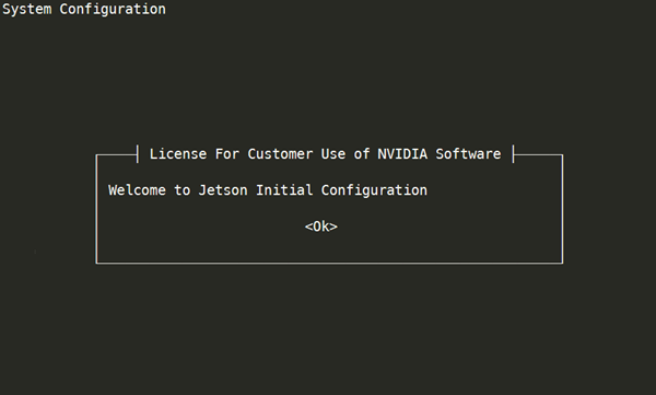
2. oem-config displays the license that governs its use. Read the license, then accept it by pressing Tab, then Enter.

3. oem-config displays a screen that lists languages. Use the up and down-arrow keys to select the language you want to use for the installation process. Then press the left and right-arrow keys to select “OK,” and press Enter.

Note | To go back from any screen to the preceding one, select “Cancel” and press Enter. You can go back more than one screen by doing this more than once. |
4. oem-config displays a screen that lists locations in which the language you selected is used. Select your location; then select “OK” and press Enter.

5. oem-config displays a screen that lists keyboard layouts. Select your keyboard’s layout, then select “OK” and press Enter.

6. oem-config displays a screen that lists time zones that exist in the location you select. Select your time zone, then select “OK” and press Enter.

If your time zone is not listed, select “Cancel” as many times as necessary to go back to the screen that lists locations, and choose a different location.
7. oem-config asks whether you want to set the system clock to Universal Coordinated Time (UTC, or Greenwich Mean Time). Linux expects the system clock to be set to UTC; therefore, NVIDIA recommends that you select “Yes” and press Enter. If you are using another operating system that expects the system clock to set to local time, however, select “No.”

8. oem-config asks you to specify your name. Enter your full name (e.g. John Smith), then select “OK” and press Enter.

9. oem-config asks you to specify a username for your user account. oem-config creates a user account for this name. then select “OK” and press Enter.
NVIDIA suggests using your first name, using lower case letters only. Use this account instead of the root account for non-administrative activities.

10. oem-config asks you to specify a password for your user account. Enter a password, then select “OK” and press Enter.
NVIDIA recommends that you specify a strong password, i.e. one that is more than eight characters long and contains at least one each of upper and lower case letters, numerals, and punctuation characters. If you enter a weak password, oem-config will ask you to confirm that you want to use it.

11. oem-config asks you to enter your password again to confirm that you entered it correctly. If you enter the same password both times, it sets the password and goes on to the next step. If not, it prompts you to specify a password again.

12. oem‑config prompts you to create and enable a 4 GB swap file. It first displays a message which summarizes the pluses and minuses of doing so:

Read the message and decide whether to create a swap file. Then press Enter to advance to the next screen:

To create and enable a swap file, select “Yes” and press Enter. To skip this step, select “No” and press Enter.
Note | As the “Create Swap File” screen explains, NVIDIA recommends that you create and enable a swap file if you plan to use your Jetson device for artificial intelligence (AI) and deep learning applications. Note that having a swap file may shorten life of you SD card due to increased writes to the medium. If you do not create a swap file in oem-config, you can later create one manually as described in the section To create and enable a swap file manually. |
13. oem-config prompts you to specify the desired size of the APP partition in megabytes. To request the maximum possible size, leave the field empty or enter 0 (zero).

Note | This is only the case of “Flashing to an SD card.” For the other case, which uses flash.sh, you can of course enlarge the APP partition statically with flash option ‑S. |
14. oem-config displays a list of interfaces which it can use as the primary network interface during installation.
If you are using Ethernet as the primary network interface, make sure the Ethernet cable is connected. Then select the eth0: Ethernet option, select “OK,” and press Enter.

Note | Due to a known wireless network configuration bug in in this wizard, you must either enter the SSID manually instead for selecting it from the list, or wait until after initial setup is complete, then use the nmcli command to configure wireless networking. For more details see the ubuntu.com documentation page Configure WiFi Connections. |
15. oem-config prompts you to enter your host computer’s host name. If you don’t know the host’s name, ask your network administrator. If you are setting up a dedicated network, you may choose any name. Enter the hostname, then select “OK,” and press Enter.

16. oem-config prompts you to select an nvpmodel mode:

If you don’t know which mode to select, keep the default setting (highlighted on the screen).
You can change the nvpmodel mode at runtime through the nvpmodel GUI. For more information go to the topic Clock Frequency and Power Management, and read the “nvpmodel GUI” subsection in the appropriate “Power Management” section for your Jetson platform.
17. oem-config reconfigures the system with the selections you have made, then proceeds to the system’s log-in prompt.
To create and enable a swap file manually
This procedure is an alternative to step 12 of the section To reconfigure the target device with oem-config. You may perform it at any time after you run oem-config.
1. To create the swap file, enter these commands:
sudo fallocate -l 4G /swapfile
sudo chmod 600 /swapfile
sudo mkswap /swapfile
sudo swapon /swapfile
2. To automount the swap file on boot, open /etc/fstab in a text editor, add this line, and save:
/swapfile swap swap defaults 0 0
Note | The fields in this line may be separated by any combination and number of tabs and spaces. NVIDIA recommends spacing the fields to align with the fields in the file’s other lines. |
Skipping oem-config
If you don't want to run oem-config to set up your system, you can run the host script l4t_create_default_user.sh before you flash to make the first-time boot process skip it. The boot process runs oem‑config if no default user is defined; l4_create_default_user.sh creates a default user, and thus prevents oem‑config from running.
The script’s usage is:
$ l4t_create_default_user.sh [‑u <user>] [‑p <pswd>] [‑n <host>] [‑a] [‑h]
This table describes the command line options:
Command line option | Description |
|---|---|
-u <user> ‑‑username <user> | Creates a default user with the specified username. If omitted, the script creates a default user named nvidia. |
-p <pswd> ‑‑password <pswd> | Creates the default user with the specified password. If omitted, script generates a random password. |
‑n <host> ‑‑hostname <host> | Creates the default user with the specified hostname. If this option is omitted, the script uses the host name tegra-ubuntu. |
‑a ‑‑autologin | Configures Jetson Linux to log in to the default user automatically when booted. If omitted, the user must log in manually. |
‑‑accept-license | Accepts the EULA for NVIDIA software. If omitted, the script prompts you to accept the EULA. |
‑h ‑‑help | Prints a description of the script’s usage. |
Examples
• Creates a user named nvidia with the password NDZjMWM4 and the hostname tegra-ubuntu.
$ l4t_create_default_user.sh -u nvidia -p NDZjMWM4
• Creates a user named ubuntu with a randomly generated password and the host name tegra-ubuntu, and configures Jetson Linux to log in to it automatically at boot.
$ l4t_create_default_user.sh -u ubuntu -a
• Creates a user named nvidia with a randomly generated password and the hostname tegra.
$ l4t_create_default_user.sh -n tegra
Modifying Jetson RAM Disk
Use the following procedure to modify the default configuration of a Jetson device’s RAM disk.
To modify RAM disk
1. Unpack your initrd:
$ sudo su
$ cp /boot/initrd /tmp
$ mkdir /tmp/temp
$ cd /tmp/temp
$ gunzip -c /tmp/initrd | cpio -i
2. Modify your initrd content in the tmp/temp/ folder:
3. Package your initrd:
$ sudo su
$ cd /tmp/temp
$ find . | cpio -H newc -o | gzip -9 -n > ../initrd
4. Replace the initrd with your customized initrd:
$ cp /tmp/initrd /boot/initrd