Hardware Setup
When developing systems and application software with an NVIDIA® Jetson™ device and Linux, you run and test your code on an actual reference platform, such as the NVIDIA® Jetson Nano™ Developer Kit. Your code targets this hardware directly, rather than a software simulator or emulator.
Accordingly, you must acquire and set up your carrier board before using L4T. Consult your board documentation for guidance on setting up and configuring your board. See the sections below for additional notes.
Jetson Developer Kit Setup
This section provides additional notes that apply to the Jetson Developer Kit for specific Jetson modules.
Jetson Xavier NX Series
NVIDIA® Jetson Xavier™ NX is a small, economical module with a moderate amount of memory. It uses the same processor as the more powerful NVIDIA Jetson AGX Xavier™ series.
Three types of Jetson Xavier NX modules are available:
• Part number P3668-0000 is distributed with Jetson Xavier NX Developer Kit. It has 8 GB of memory and an on-module SD card socket which enables you to program it by inserting an SD card flashed with operating software on another computer.
• Part number P3668-0001 is sold for production use, and is also compatible with Jetson Xavier NX Developer Kit. It has 8 GB of on-board eMMC memory but lacks an SD card socket.
• Part number P3668-0003 is is also sold for production use, and is identical with P3668-0001 except that it has 16 GB of memory.
For more information about Jetson Xavier NX series modules, see the Jetson Xavier NX Module Data Sheet.
Carrier Board Preparation
Although the carrier board supports a variety of peripheral devices, start developing your application with a board that has the following:
• A 16 GB or larger UHS-1 microSD card for flashing the operating system and other software.
• A USB cable to plug into USB Micro‑B connector.
For flashing instructions, see “Developer Kit Setup” in Jetson Xavier NX Developer Kit User Guide.
Carrier Board Layout
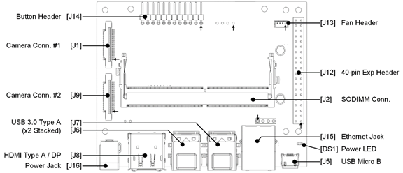
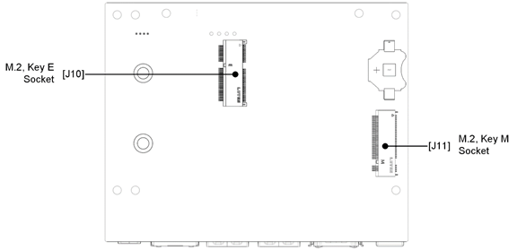
The Jetson Xavier NX board layout and connections are shown in the following diagrams.
Jetson NX reference carrier board: top view

Jetson NX reference carrier board: bottom view

Jetson Nano Devices
Three types of Jetson Nano modules are available:
• P3448-0000 (a version of original Jetson Nano for development work), included in Jetson Nano Developer Kit
• P3448-0002 (a version of original Jetson Nano for production uses); may also be used on the carrier board in Jetson Nano Developer Kit, revision B01 or newer
• P3448-0003 (Jetson Nano 2GB, for development and educational uses only), included in the Jetson Nano 2GB Developer Kit
The three modules are collectively described as “Jetson Nano devices.” When the modules must be distinguished, P3448-0000 and P3448-0002 (“P3448 SKU 0000” and “SKU 0002”) are both called “Jetson Nano.” P3448-003 (“SKU 0003”) is called “Jetson Nano 2GB.” The Jetson Nano Developer Kit and Jetson Nano 2GB Developer Kit” are collectively described as “Jetson Nano developer kits.”
All of the Jetson Nano modules are functionally identical. For more information about these modules, see the Jetson Nano Module Data Sheet.
Carrier Board Preparation
Although the carrier board supports a variety of peripheral devices, start developing your application with a board that has the following:
• A USB cable to plug into the board recovery port.
Carrier Board Layout
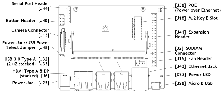
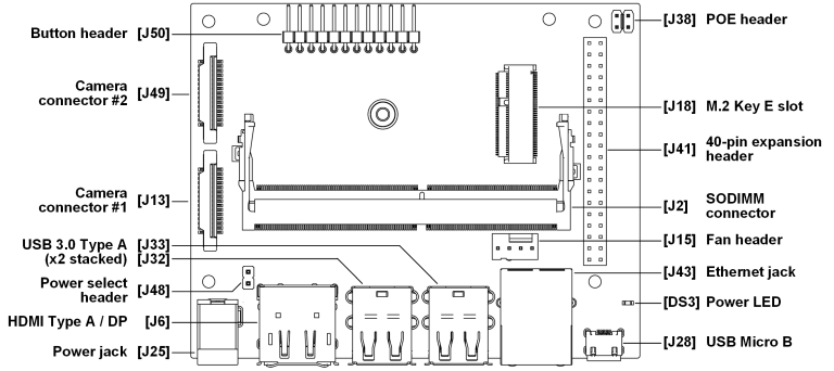
The following diagrams show Jetson Nano carrier board layout and connections for board revisions A02 and B01.
Jetson Nano reference carrier board revision A02: top view

Jetson Nano reference carrier board revision B01: top view

Jetson Nano 2GB reference carrier board: top view

Jetson AGX Xavier Series Devices
Two types of NVIDIA® Jetson AGX Xavier™ series modules are available:
• The original Jetson AGX Xavier module, with 16 GB of memory, used in the original Jetson AGX Developer Kit and available as a production module.
• The revised Jetson AGX Xavier module with 32 GB of memory, used in the revised Jetson AGX Xavier Developer Kit and available as a production module.
For more information about Jetson AGX Xavier modules, see the Jetson AGX Xavier Series Module Data Sheet.
Carrier Board Preparation
Although the carrier board supports a variety of peripheral devices, start developing your application with a board that has the following:
• A USB‑C cable to plug into the board’s USB‑C flash port.
Carrier Board Layout
The Jetson AGX Xavier series carrier board layout and connections are shown in the following diagram.
Jetson AGX Xavier carrier board: top view

Jetson AGX Xavier carrier board: bottom view

Jetson AGX Xavier Industrial Information
This section contains additional information about several aspects of Jetson AGX Xavier Industrial.
Error Correcting Code (ECC) DRAM
Jetson AGX Xavier Industrial uses error correction code (ECC) DRAM. It supports these features:
• Staged DRAM scrubbing in MB1, MB2, and CBoot; reduces boot time compared to full DRAM scrubbing in MB1
• Single-bit error correction in the Safety Cluster Engine (SCE) firmware
• Double-bit error detection and reboot in the SCE firmware
For more information about the SCE, see Xavier Series SoC Technical Reference Manual.
ECC reserves 12.5% of memory for parity bits, reducing memory bandwidth by 12.5% when ECC is enabled.
Error correction is enabled by default. Use the following procedure to disable it.
To disable Jetson AGX Xavier Industrial ECC DRAM
1. Open the configuration file at <top>/Linux_for_Tegra/jetson-agxi.conf.
2. Comment out the following lines (prefix each with a semicolon):
EMMC_BCT="tegra194-mb1-bct-memcfg-4x-derated-ecc-p2888.cfg";
MISC_CONFIG="tegra194-mb1-bct-misc-flash-jaxi.cfg";
MISC_COLD_BOOT_CONFIG="tegra194-mb1-bct-misc-l4t-jaxi.cfg";
3. Save the configuration file.
4. Reboot the Jetson device. It will boot with ECC disabled.
Jetson TX2 Series Devices
Three types of Jetson TX2 series modules are available:
• The original Jetson TX2 module
• Jetson TX2i, an industrial version of the original Jetson TX2, designed for 24/7 operation, a longer operating life, and a broader range of operating conditions
• Jetson TX2 4GB, a low-priced module with reduced memory and storage
For more information about Jetson TX2 modules, see the Jetson TX2 Series Module Data Sheet.
Carrier Board Preparation
The Jetxon TX2 Developer Kit is sold only with an original Jetson TX2 processor, but the carrier board is compatible with all Jetson TX2 series devices.
Although the carrier board supports a variety of peripheral devices, start developing your application with a board that has the following:
• A USB cable to plug into the board recovery port
Carrier Board Layout
There are several revisions of the Jetson TX2 reference carrier board. Two of the three most common ones, B04 and C02, are shown below. The third, B02 is very similar to B04.
Note: | Jetson TX2 series devices and NVIDIA® Jetson™ TX1 devices use the same carrier board; only the Jetson module differs. Thus, these diagrams apply to both Jetson TX2 and Jetson TX1. |
Jetson TX2/TX1 reference carrier board revision B04: top view

Jetson TX2/TX1 reference carrier board revision C02: top view

Jetson TX2i Information
This section contains additional information about several aspects of Jetson TX2i.
Power Profiles
Jetson TX2i works with two power profiles, UCM1 and UCM2. The UCM1 profile is the default.
The following table describes the power profiles.
Power Profile | Temp | Mission Profile | Operating Lifetime | Unit | VMAX Volts | FMAX MHz |
|---|---|---|---|---|---|---|
Notes | ||||||
UCM1 | 90° C | 24/7 | 10 years | GPU | 0.945 | 1236.75 |
CPU (D15/A57) | 0.945 | 1958/1920 | ||||
EMC/SOC | 0.945 | 1600 | ||||
With voltage and frequency settings specified, system operational life at maximum temperature 90 °C is 10 years. | ||||||
105 °C | 8 hours/day | 10 years | GPU | 0.945 | 1236.75 | |
CPU (D15/A57) | 0.945 | 1958/1920 | ||||
EMC/SOC | 0.945 | 1600 | ||||
To ensure an operational life of 10 years, a Jetson TX2i system must operate above 100 °C for no more than 8 hours/day, and 80 °C or less for the remaining time. The absolute maximum operating temperature is 105 °C. | ||||||
80 °C | 16 hours/day | 10 years | GPU | 0.945 | 1236.75 | |
CPU (D15/A57) | 0.945 | 1958/1920 | ||||
EMC/SOC | 0.945 | 1600 | ||||
UCM2 | 105 °C | 24/7 | 4.4 years | GPU | 0.8 | 918 |
CPU (D15/A57) | 0.8 | 1497/1420 | ||||
EMC/SOC | 0.83 | 1600 | ||||
With the voltage and frequency settings specified, the system’s operational life is 4.4 years. | ||||||
To use the UCM2 power profile:
1. On your Linux host computer, navigate to the Jetson TX2i configuration file, jetson-tx2i.conf. This file is a soft link to p2771-3489-ucm1.conf.
2. Change the soft link to p2771-3489-ucm2.conf.
3. Flash the module.
Compatibility Issues
Compatibility issues noted with the Jetson TX2i module include:
• Jetson TX2i is compatible only with P2597 carrier board revision B04 or newer.
• A Jetson TX2i system cannot be shut down from software. Any shutdown attempt reboots the device. The Linux shutdown command also reboots the device.
• The power button [S4] does not work correctly on reference carrier board revision B04. It works correctly on revision C02.
Flashing Support
Carrier Board Compatibility
Jetson TX2i does not have a dedicated reference carrier board. It is compatible with the Jetson TX2 carrier board (P2822), which is included in the Jetson TX2 Developer Kit (P2771). Consult Jetson Developer Kit Carrier Board Specification for notes about using Jetson TX2i with various revisions of the P2597 carrier board.
Operating Profiles
Jetson TX2i may be used in any of these profiles:
Mission profile and operating temperature | Operating lifetime | Unit | VMAX V | FMAX MHz |
24 hours/day at 90 °C | 10 years | GPU | 0.945 | 1236.75 |
CPU (D15/A57) | 0.945 | 1958/1920 | ||
EMC/SOC | 0.945 | 1600 | ||
8 hours/day at 105° C and 16 hours/day at 80 °C | 10 years | GPU | 0.945 | 1236.75 |
CPU (D15/A57) | 0.945 | 1958/1920 | ||
EMC/SOC | 0.945 | 1600 | ||
24 hours/day at 105 °C | 4.4 years | GPU | 0.8 | 918 |
CPU (D15/A57) | 0.8 | 1497/1420 | ||
EMC/SOC | 0.83 | 1600 |
Feature Support for Error Correction Code (ECC) DRAM
Jetson TX2i supports DRAM ECC, which is enabled by default.
Note: | ECC does not function on the original Jetson TX2. |
The Error Correction Code (ECC) features include:
• Full DRAM scrubbing in MB1 to generate parity bits required for ECC
• SBE Correction in the SCE firmware
• DBE detection and reboot in the SCE firmware
• Memory available to the kernel extended from two regions to the actual available regions
• Position independent U‑Boot support
Memory bandwidth is reduced when ECC is enabled. ECC reserves 12.5% of memory for parity bits, causing a 12.5% reduction in memory bandwidth.
Jetson TX1
This section describes hardware setup for NVIDIA Jetson TX1 devices.
For more information about Jetson TX1 modules, see the Jetson TX1 Series Module Data Sheet.
Carrier Board Preparation
Although the carrier board supports a variety of peripheral devices, start developing your application with a board that has:
• A USB cable to plug in to the board recovery port.
Carrier Board Layout
The Jetson TX1 module uses the same reference carrier boards as the Jetson TX2, shown in the Jetson TX2 sectionPlatform Carrier Board Layout.
Enabling Bluetooth Audio
Hardware support for Bluetooth® audio varies by platform. The following table summarizes the support provided in each case:
Platform | SoC | Bluetooth Support | ||||
|---|---|---|---|---|---|---|
On SoC | ||||||
Through M.2 key E connector; customer must add Bluetooth hardware on production systems * | ||||||
Through M.2 Key E connector; customer must supply Bluetooth hardware | ||||||
No Bluetooth support | ||||||
Jetson Xavier NX series | T194 | X | ||||
Jetson Nano devices | T210 | X | ||||
Jetson AGX Xavier series | T194 | X | ||||
Jetson TX2 4GB | T186 | X | ||||
Jetson TX2i | T186 | X | ||||
Jetson TX2 (original, 8GB) | T186 | X | ||||
Jetson TX1 | T210 | X | ||||
* Carrier boards have built-in Bluetooth support for development. | ||||||
To ensure the Bluetooth software stack is conformant for the configuration, Bluetooth audio is disabled by default. If additional Bluetooth audio profiles are enabled, product conformance may be impacted.
To enable Bluetooth audio
1. Navigate to this file:
/lib/systemd/system/bluetooth.service.d/nv-bluetooth-service.conf
2. Use a text editor to change this line…
ExecStart=/usr/lib/bluetooth/bluetoothd -d --noplugin=audio,a2dp,avrcp
…to this:
ExecStart=/usr/lib/bluetooth/bluetoothd -d
(That is, delete the ‑‑noplugin option and all of its values.)
3. Enter these commands to update the apt-get package list and install the pulse audio package:
$ sudo apt-get update
$ sudo apt-get install pulseaudio-module-bluetooth
4. Enter this command to reboot the Jetson device:
$ sudo reboot
5. When the reboot is complete, pair and connect any Bluetooth headset.
Voltage and Current Monitor
Jetson modules include an on-board power monitor, the INA3221, to monitor the voltage and current of certain rails. L4T uses the power monitor to implement a system Electrical Design Point (EDP) management strategy which maximizes CPU and GPU performance within system EDP constraints for the platform.
The Jetson module feeds INA3221 outputs into SOC_THERM input. When one or more alert outputs are asserted, the SOC_THERM hardware reduces module power consumption to avoid violating current limits.
The power monitor accepts configuration data from powermon.dtsi (the source file). The following sections describe the device tree properties that you may need to change to configure the power monitor, and for each supported platform, the location of the file and a code snippet showing how the properties are used.
Power Monitor Device Tree Properties
These are the power monitor device tree properties that you may need to change to configure the power monitor.
• ti,continuous-config: INA3221 continues conversion mode configuration register setting, determines channels enabled, bus voltage conversion time, and number of samples collected and averaged together.
• ti,trigger-config: INA3221 single shot conversion mode configuration register setting.Determines channels enabled, bus voltage conversion time, and number of samples collected and averaged together.
• ti,rail-name: Name of the power rail connected to the INA3221 input channel.
• ti,shunt-resistor-mohm: Power rail sense resistor value, in milliohms.
• ti,current-warning-limit-ma: Channel average current limit in milliamperes. The INA3221 warning signal is asserted when the channel’s average current exceeds this limit, triggering CPU/GPU hardware throttling via Jetson SOCTHEM_OC.
• ti,current-critical-limit-ma: Channel instantaneous current limit in milliamperes. The INA3221 critical signal is asserted when the channel’s instantaneous current exceeds this limit, triggering CPU/GPU hardware throttling via Jetson SOCTHEM_OC.
Jetson Xavier NX Series
The INA3221 monitors the voltage and current of the following power rails:
• VDD_IN
• VDD_CPU_GPU_CV
• VDD_SOC
The alert outputs of the INA3221 include:
• CRIT
• WARN
Configuring the Voltage and Current Monitor
The Xavier NX module’s input power rail VDD_IN is connected to channel 0 and configured to trigger CPU/GPU hardware throttling when average current goes above 3000 mA or instantaneous current goes above 3600 mA.
The device tree source file is located at:
hardware/nvidia/platform/t19x/jakku/kernel-dts/common/tegra194-powermon-p3668.dtsi
The following code snippet is from this file:
i2c@c250000 {
ina3221x_40: ina3221x@40 {
compatible = "ti,ina3221x";
reg = <0x40>;
ti,trigger-config = <0x7003>;
ti,continuous-config = <0x7c07>;
ti,enable-forced-continuous;
#address-cells = <1>;
#size-cells = <0>;
#io-channel-cells = <1>;
channel@0 {
reg = <0x0>;
ti,rail-name = "VDD_IN";
ti,shunt-resistor-mohm = <5>;
ti,current-warning-limit-ma = <3000>;
ti,current-critical-limit-ma = <3600>;
};
channel@1 {
reg = <0x1>;
ti,rail-name = "VDD_CPU_GPU_CV";
ti,shunt-resistor-mohm = <5>;
};
channel@2 {
reg = <0x2>;
ti,rail-name = "VDD_SOC";
ti,shunt-resistor-mohm = <5>;
};
};
};
Jetson Nano Devices
The INA3221 monitors the voltage and current of the following power rails:
• POM_5V_IN
• POM_5V_CPU
• POM_5V_GPU
The alert outputs of the INA3221 include:
• CRIT
• WARN
Configuring the Voltage and Current Monitor
The powermon.dtsi file for the Jetson Nano module is located at:
hardware/nvidia/platform/t210/porg/kernel-dts/porg-platforms/tegra210-porg-powermon-p3448-0000-a00.dtsi
The following code snippet is from this file:
i2c@546c0000 {
ina3221x: ina3221x@40 {
compatible = "ti,ina3221x";
reg = <0x40>;
status="okay";
ti,trigger-config = <0x7003>;
ti,continuous-config = <0x7607>;
ti,enable-forced-continuous;
#io-channel-cells = <1>;
#address-cells = <1>;
#size-cells = <0>;
channel@0 {
reg = <0x0>;
ti,rail-name = "POM_5V_GPU";
ti,shunt-resistor-mohm = <5>;
};
channel@1 {
reg = <0x1>;
ti,rail-name = "POM_5V_IN";
ti,shunt-resistor-mohm = <5>;
};
channel@2 {
reg = <0x2>;
ti,rail-name = "POM_5V_CPU";
ti,shunt-resistor-mohm = <5>;
};
};
};
Jetson AGX Xavier Series
The INA3221 monitors the voltage and current of the following power rails:
• GPU
• CPU
• SOC
• CV
• VDDRQ
• SYS5V
The alert outputs of the INA3221 include:
• CRIT and WARN (tied together routed to the VMON (SOC_GPIO07) pin
Configuring the Voltage and Current Monitor
The powermon.dtsi file for the Jetson AGX Xavier series modules is located at:
hardware/nvidia/platform/t19x/galen/kernel-dts/common/tegra194-powermon-p2888.dtsi
The following code snippet is from this file:
i2c@c240000 {
ina3221x_40: ina3221x@40 {
compatible = "ti,ina3221x";
reg = <0x40>;
ti,trigger-config = <0x7003>;
ti,continuous-config = <0x7c07>;
ti,enable-forced-continuous;
#address-cells = <1>;
#size-cells = <0>;
#io-channel-cells = <1>;
channel@0 {
reg = <0x0>;
ti,rail-name = "GPU";
ti,shunt-resistor-mohm = <5>;
shunt-volt-offset-uv = <&p2888_shuntv_offset>;
};
channel@1 {
reg = <0x1>;
ti,rail-name = "CPU";
ti,shunt-resistor-mohm = <5>;
shunt-volt-offset-uv = <&p2888_shuntv_offset>;
};
channel@2 {
reg = <0x2>;
ti,rail-name = "SOC";
ti,shunt-resistor-mohm = <5>;
shunt-volt-offset-uv = <&p2888_shuntv_offset>;
};
};
ina3221x_41: ina3221x@41 {
compatible = "ti,ina3221x";
reg = <0x41>;
ti,trigger-config = <0x7003>;
ti,continuous-config = <0x7c07>;
ti,enable-forced-continuous;
#address-cells = <1>;
#size-cells = <0>;
#io-channel-cells = <1>;
channel@0 {
reg = <0x0>;
ti,rail-name = "CV";
ti,shunt-resistor-mohm = <5>;
shunt-volt-offset-uv = <&p2888_shuntv_offset>;
};
channel@1 {
reg = <0x1>;
ti,rail-name = "VDDRQ";
ti,shunt-resistor-mohm = <5>;
shunt-volt-offset-uv = <&p2888_shuntv_offset>;
};
channel@2 {
reg = <0x2>;
ti,rail-name = "SYS5V";
ti,shunt-resistor-mohm = <5>;
shunt-volt-offset-uv = <&p2888_shuntv_offset>;
};
};
};
Jetson TX2 Series (Except Jetson TX2 NX)
The INA3221 monitors the voltage and current of the following power rails:
• VDD_IN
• VDD_CPU
• VDD_GPU
• VDD_SOC
• VDDIO_DDR
• VDD_WIFI (original Jetson TX2 only)
The alert outputs of the INA3221 include:
• CRIT and WARN (tied together and routed to SoC input on SOC_THERM)
The outputs are fed into a SOC_THERM input on the Jetson module. When one or more alert outputs are asserted, the SOC_THERM hardware reacts to reduce module power consumption and avoid violating current limits.
Configuring the Voltage and Current Monitor
By default, the Jetson TX2 developer kit’s critical current limit of VDD_IN is set to the maximum possible value of 8190 mA. Therefore, it is not necessary to modify the critical current for lower input voltage unless you want to configure the critical current limit for a specific input voltage.
Jetson TX2
The powermon.dtsi file for the Jetson TX2 module is located at:
hardware/nvidia/platform/t18x/common/kernel-dts/t18x-common-platforms/tegra186-quill-p3310-1000-a00-powermon.dtsi
The following code snippet is from this file:
i2c@3160000 {
ina3221x_40: ina3221x@40 {
compatible = "ti,ina3221x";
reg = <0x40>;
ti,trigger-config = <0x7003>;
ti,continuous-config = <0x7c07>;
ti,enable-forced-continuous;
#address-cells = <1>;
#size-cells = <0>;
#io-channel-cells = <1>;
channel@0 {
reg = <0x0>;
ti,rail-name = "VDD_SYS_GPU";
ti,shunt-resistor-mohm = <5>;
};
channel@1 {
reg = <0x1>;
ti,rail-name = "VDD_SYS_SOC";
ti,shunt-resistor-mohm = <5>;
};
channel@2 {
reg = <0x2>;
ti,rail-name = "VDD_4V0_WIFI";
ti,shunt-resistor-mohm = <10>;
};
};
ina3221x_41: ina3221x@41 {
compatible = "ti,ina3221x";
reg = <0x41>;
ti,trigger-config = <0x7003>;
ti,continuous-config = <0x7c07>;
ti,enable-forced-continuous;
#address-cells = <1>;
#size-cells = <0>;
#io-channel-cells = <1>;
channel@0 {
reg = <0x0>;
ti,rail-name = "VDD_IN";
ti,shunt-resistor-mohm = <1>;
};
channel@1 {
reg = <0x1>;
ti,rail-name = "VDD_SYS_CPU";
ti,shunt-resistor-mohm = <5>;
};
channel@2 {
reg = <0x2>;
ti,rail-name = "VDD_SYS_SRAM";
ti,shunt-resistor-mohm = <5>;
};
};
};
Jetson TX2i
The powermon.dtsi file for the Jetson TX2i module is located at:
hardware/nvidia/platform/t18x/common/kernel-dts/t18x-common-platforms/tegra186-quill-p3489-1000-a00-powermon.dtsi
The following code snippet is from this file:
i2c@3160000 {
ina3221x_40: ina3221x@40 {
compatible = "ti,ina3221x";
reg = <0x40>;
ti,trigger-config = <0x7003>;
ti,continuous-config = <0x7c07>;
ti,enable-forced-continuous;
#address-cells = <1>;
#size-cells = <0>;
channel@0 {
reg = <0x0>;
ti,rail-name = "VDD_SYS_GPU";
ti,shunt-resistor-mohm = <5>;
};
channel@1 {
reg = <0x1>;
ti,rail-name = "VDD_SYS_SOC";
ti,shunt-resistor-mohm = <5>;
};
};
ina3221x_41: ina3221x@41 {
compatible = "ti,ina3221x";
reg = <0x41>;
ti,trigger-config = <0x7003>;
ti,continuous-config = <0x7c07>;
ti,enable-forced-continuous;
#address-cells = <1>;
#size-cells = <0>;
channel@0 {
reg = <0x0>;
ti,rail-name = "VDD_IN";
ti,shunt-resistor-mohm = <1>;
};
channel@1 {
reg = <0x1>;
ti,rail-name = "VDD_SYS_CPU";
ti,shunt-resistor-mohm = <5>;
};
channel@2 {
reg = <0x2>;
ti,rail-name = "VDD_SYS_SRAM";
ti,shunt-resistor-mohm = <5>;
};
};
};
Jetson TX2 NX
The INA3221 monitors the voltage and current of the following power rails:
• VDD_IN
• VDD_CPU_GPU
• VDD_SOC
The alert outputs of the INA3221 include:
• CRIT
• WARN
Configuring the Voltage and Current Monitor
The TX2 NX module input power rail VDD_IN is connected to channel 0 and configured to trigger CPU/GPU hardware throttling when average current goes above 3000 mA or instantaneous current goes above 3600 mA.
The device tree source file is located at:
/hardware/nvidia/platform/t18x/lanai/kernel-dts/common/tegra186-p3636-0001-a00-powermon.dts
The following code snippet is from this file:
ina3221x_40: ina3221x@40 {
compatible = "ti,ina3221x";
reg = <0x40>;
ti,trigger-config = <0x7003>;
ti,continuous-config = <0x7c07>;
ti,enable-forced-continuous;
#address-cells = <1>;
#size-cells = <0>;
#io-channel-cells = <1>;
channel@0 {
reg = <0x0>;
ti,rail-name = "VDD_IN";
ti,shunt-resistor-mohm = <5>;
ti,current-warning-limit-ma = <3000>;
ti,current-critical-limit-ma = <3600>;
};
channel@1 {
reg = <0x1>;
ti,rail-name = "VDD_CPU_GPU";
ti,shunt-resistor-mohm = <5>;
};
channel@2 {
reg = <0x2>;
ti,rail-name = "VDD_SOC";
ti,shunt-resistor-mohm = <5>;
};
};
Jetson TX1
The INA3221 monitors the voltage and current of the following power rails:
• VDD_IN
• VDD_CPU
• VDD_GPU
The alert outputs of the INA3221 are:
• CRIT
• WARN
Configuring the Voltage and Current Monitor
The base powermon.dtsi file for the Jetson TX1 module is located at:
hardware/nvidia/platform/t210/jetson/kernel-dts/jetson-platforms/tegra210-jetson-cv-powermon-p2597.dtsi
This file contains settings for INA channels 1 and 2.
The following code snippet is from this file:
/ {
i2c@7000c400 {
ina3221x@42 {
compatible = "ti,ina3221x";
reg = <0x42>;
ti,trigger-config = <0x7003>;
ti,continuous-config = <0x7607>;
ti,enable-forced-continuous;
#io-channel-cells = <1>;
#address-cells = <1>;
#size-cells = <0>;
status = "okay";
channel@0 {
reg = <0x0>;
ti,rail-name = "VDD_MUX";
ti,shunt-resistor-mohm = <20>;
};
channel@1 {
reg = <0x1>;
ti,rail-name ="VDD_5V_IO_SYS";
ti,shunt-resistor-mohm = <5>;
};
channel@2 {
reg = <0x2>;
ti,rail-name = "VDD_3V3_SYS";
ti,shunt-resistor-mohm = <10>;
};
};
ina3221x@43 {
compatible = "ti,ina3221x";
reg = <0x43>;
ti,trigger-config = <0x7003>;
ti,continuous-config = <0x7607>;
ti,enable-forced-continuous;
#io-channel-cells = <1>;
#address-cells = <1>;
#size-cells = <0>;
status = "okay";
channel@0 {
reg = <0x0>;
ti,rail-name = "VDD_3V3_IO";
ti,shunt-resistor-mohm = <10>;
};
channel@1 {
reg = <0x1>;
ti,rail-name = "VDD_1V8_IO";
ti,shunt-resistor-mohm = <10>;
};
channel@2 {
reg = <0x2>;
ti,rail-name = "VDD_M2_IN";
ti,shunt-resistor-mohm = <10>;
};
};
};
};
The plugin manager’s powermon.dtsi file for the Jetson TX1 module is located at:
hardware/nvidia/platform/t210/jetson/kernel-dts/jetson-platforms/tegra210-jetson-cv-powermon-p2180-1000-a00.dtsi
Note: | This file contains settings for INA channel 0. |
The following code snippet is from this file:
i2c@7000c400 {
ina3221x: ina3221x@40 {
compatible = "ti,ina3221x";
reg = <0x40>;
ti,trigger-config = <0x7003>;
ti,continuous-config = <0x7607>;
ti,enable-forced-continuous;
#io-channel-cells = <1>;
#address-cells = <1>;
#size-cells = <0>;
status = "disabled";
channel@0 {
reg = <0x0>;
ti,rail-name = "VDD_IN";
ti,shunt-resistor-mohm = <20>;
ti,power-critical-limit-mw = <40000>;
shunt-volt-offset-uv = <&p2180_shuntv_offset>;
};
channel@1 {
reg = <0x1>;
ti,rail-name = "VDD_GPU";
ti,shunt-resistor-mohm = <10>;
shunt-volt-offset-uv = <&p2180_shuntv_offset>;
};
channel@2 {
reg = <0x2>;
ti,rail-name = "VDD_CPU";
ti,shunt-resistor-mohm = <10>;
shunt-volt-offset-uv = <&p2180_shuntv_offset>;
};
};
};