Display Configuration and Bring-Up
NVIDIA® Jetson™ Board Support Package (BSP) supports a variety of modes on HDMI® and DP monitors, including the CEA modes and detailed timing modes from the display EDID.
For Jetson AGX Orin : Enabling HDMI on Custom Carrier Boards
This information is specific for modifying the device tree file for your custom carrier board and does not apply when you use the Developer Kit carrier board.
Download the example HDMI DTS file
Download the “tegra234-dcb-p3701-0000-a02-p3737-0000-a01_hdmi.dtsi” file from https://developer.nvidia.com/embedded/jetson-linux-r3411.
Modify kernel dts with HDMI connector support
The JetPack5.0-DP release Kernel sources includes a dtsi file that sets DCB with DP connector support by default. Users will need to update the provided dtsi file with the downloaded dtsi file to enable HDMI setting.
Path: <Kernel_Sources>/hardware/nvidia/platform/t23x/concord/kernel-dts/
Modify your board dts to replace the default DCB dtsi:
--- a/tegra234-p3701-0000-p3737-0000.dts
+++ b/tegra234-p3701-0000-p3737-0000.dts
@@ -17,7 +17,7 @@
#include "cvm/tegra234-p3701-0000.dtsi"
#include "cvb/tegra234-p3737-0000-a00.dtsi"
#include "tegra234-power-tree-p3701-0000-p3737-0000.dtsi"
-#include "tegra234-dcb-p3701-0000-a02-p3737-0000-a01.dtsi"
+#include "tegra234-dcb-p3701-0000-a02-p3737-0000-a01_hdmi.dtsi"
#include <tegra234-soc/mods-simple-bus.dtsi>
#include "cvb/tegra234-p3737-camera-modules.dtsi"
Recompile the Kernel by completing instructions in Kernel Customization .
Reflash your board with the updated Kernel and Kernel DTB
Known Limitation
The display driver firmware present in the JP5.0-DP release only supports HDMI HPD on Main GPIO controller, Port M, pin 0:
(TEGRA234_MAIN_GPIO(M, 0))
Support to customize by using HDMI HPD on a different GPIO controller/pin/port will be provided in the JetPack 5.0 GA release.
Setting HDMI or DP Screen Resolution
The screen resolution can be modified using the xrandr utility or RandR protocol.
To change the default HDMI/DP screen resolution
Export the
DISPLAYvariable:$ export DISPLAY=:0
Obtain the applicable resolutions list:
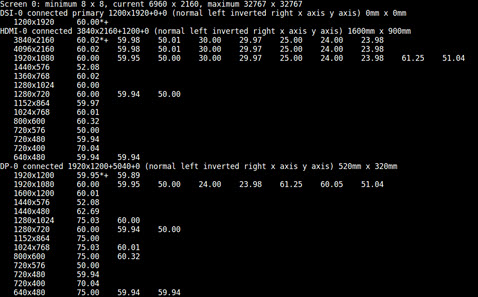
$ xrandr
The resulting output shows a list of the HDMI and DP settings, if connected.
Switch the resolution to the desired display resolution:
$ xrandr --output HDMI-0 --mode <res>
$ xrandr --output DP-0 --mode <res>
Where
<res>is the desired resolution, for example,640x480.The highest rate supported for the specified mode is automatically chosen.
Select the desired refresh rate:
$ xrandr --output HDMI-0 --mode <res> --rate <refresh_rate>
Where
<refresh_rate>is the desired refresh rate, for example,60.Use
xrandrto display all the supported refresh rates for a mode.
Mirroring or Extending Displays
When multiple displays are connected, you can choose the relative position of each monitor (HDMI or DP).
To choose the relative position of each monitor
Execute the following command to mirror the DP monitor on the HDMI monitor:
$ xrandr --output DP-0 --same-as HDMI-0
Execute the following command to extend the display environment by placing the DP monitor to the left of the HDMI monitor:
$ xrandr --output DP-0 --left-of HDMI-0
Execute this command to place the DP monitor to the right of the HDMI monitor:
$ xrandr --output DP-0 --right-of HDMI-0
Hard-coding Kernel Display Boot Mode for HDMI
The Linux kernel boot logs and text-mode login prompt fails to display
on some monitors due to a known fbconsole pixel clock calculation issue.
Affected monitors include:
Acer S277HK
Dell 24-inch 4K monitor
Viewsonic VP2780
ASUS MX27UQ
Samsung 8500 UHD TV
NEC MultiSync LCD2070VX
LG Flatron W2246
ASUS VW220TE
NVIDIA has packaged a utility to update the kernel DTB file and work around this issue.
To update the kernel DTB file
Navigate to the kernel directory at:
<top>/Linux_for_Tegra/kernel
Execute this command to update the DTB:
$ ./nv-enable-hard-coded-kernel-boot-display-mode.sh
$ dtb/tegra194-p2888-0001-p2822-0000.dtb
Flash the system.
Upon successful booting, the fbconsole displays in the specified mode. The default display mode is 720x480p@60Hz CEA.
The DTB files are available at:
kernel/dtb/tegra194-p2888-0001-p2822-0000.dtb
To specify a mode other than the default
Open the utility in your preferred editor.
In the properties array, update the values to the left of the ‘:’ (colon) for each of the mode parameters.
Save the utility script and exit the editor.
Re-execute the utility by using the instructions To update the kernel DTB file.
Guidelines
Any known working mode on the given Monitor/TV can be specified instead of the 720x480p mode.
If the
nvidia,fbcon-default-modenode already exists, the script may print an error message. It is safe to ignore this message.By default, the HDMI is mapped to SOR1 on both the platforms. If you updated it to SOR0, ensure that the node path is also updated and assigned to the fbcon_node variable in the script.
nvimp_util: A Tool for Calculating Memory Bandwidth for a Particular Display Configuration (IMP)
IMP stands for “Is Mode Possible?” It is an algorithm that you can run to determine:
Whether a proposed display configuration is possible, given certain bandwidth constraints
If the configuration is possible, the expected bandwidth values that must be programmed into the hardware to support that configuration
“Display configuration” loosely refers to the state of all active heads, windows, and cursors.
In general, several factors can impact IMP, such as the maximum downscaling factor for each active window, the surface dimensions of each window, the raster timings on a particular head, etc. IMP takes all of these factors into account.
nvimp_util is an offline utility that lets you input a display
configuration through the command line and run IMP on it. If IMP passes,
the utility outputs bandwidth values that you can specify in a device
tree to support the display configuration. This topic explains how to
use nvimp_util to run IMP and how to program device tree accordingly.
You must have sudo permissions to run this tool.
Command Line Options
Command line options for nvimp_util fall into two main categories:
per-head and per-window. The following tables describe these options.
| Required per-head options | ||
|---|---|---|
| Option name | Description | Value |
| --head <n> -h <n> |
Specifies physical display ID of a head. All other per-head options apply to this head. |
Integer
NVIDIA® Jetson AGX Xavier™ series: [0, 3] |
|
--pclkMHz <fp>
-p <fpK> |
Pixel clock value in megahertz for the head. |
Floating point
[0, MAX_FLOAT] |
|
--h_active <n>
-a <n> |
Horizontal active raster width in pixels. |
Integer
[0, MAX_INT] |
|
--h_active <n>
-a <n> |
Horizontal active raster width in pixels. |
Integer
[0, MAX_INT] |
|
--h_active <n>
-a <n> |
Horizontal active raster width in pixels. |
Integer
[0, MAX_INT] |
|
--v_active <n>
-b <n> |
Vertical active raster height in lines. |
Integer
[0, MAX_INT] |
|
--h_blank <n>
-A <n> |
Total horizontal line blanking in pixels. |
Integer
[0, MAX_INT] |
|
--v_blank <n>
-B <n> |
Total vertical blanking in lines. |
Integer
[0, MAX_INT] |
| Optional per-head options | ||
|---|---|---|
| Option name | Description | Value |
|
--cursor_active <b>
-C <b> |
Indicates whether the head’s hardware cursor is active. |
Integer
Zero (FALSE) or non-zero (TRUE) Default is FALSE |
|
--output_lut_enable <b>
-l <b> (lower case L) |
Indicates whether the head’s OLUT (Output Lookup Table) is enabled. |
Integer
Zero (FALSE) or non-zero (TRUE) Default is FALSE |
|
--output_lut_size <n>
-g <n> |
Specifies the number of entries in the OLUT.
Use only if ``output_lut_enable`` is TRUE. |
Integer
257 or 1025 No default |
Note
Per-window options may be omitted completely. The “required” options must all be specified if the --window option (optional, in the subsequent table) is present.
| Required per-window options | ||
|---|---|---|
| Option name | Description | Value |
|
--sizeInX <n>
-X <n> |
Input width of the window in pixels.
Required if e is specified. |
Integer
[1, MAX_INT] |
|
--sizeInY <n>
-y <n> |
NO if "window" is specified
The input height of the window in lines. |
Integer
[1, MAX_INT] |
|
--sizeOutX <n>
-X <n> |
NO if "window" is specified
Output width of the window in pixels. |
Integer
[1, h_active] |
|
--sizeOutY <n>
-Y <n> |
NO if "window" is specified
Output height of the window in lines. |
Integer
[1, v_active] |
| Optional per-window options | ||
|---|---|---|
| Option name | Description | Value |
|
--window <n>
-W <n> |
Specifies the physical ID of the hardware window.
Applies to the corresponding "head" argument since a window is always owned by a head. Required if any other per-window switches are specified. All other per-window switches apply to this window. |
Integer
[0, 5] No default |
|
--format <str>
-f <str> |
Input color format of the window's surface. |
String
Value must be one of:
|
|
--surface <str>
-g <str> |
Describes memory layout of the window's surface. |
String
Value must be one of:
|
|
--pointOutX <n>
-i <n> |
Output X-coordinate of the window's upper left corner in the active raster. |
Integer
[0, (h_active‒1)] Default is 0 |
|
--pointOutY <n>
-J <n> |
Output Y-coordinate of the window's upper left corner in the active raster. |
Integer
[0, (v_active‒1)] Default is 0 |
|
--pointInX <n>
-i <n> |
Input X-coordinate of the surface fetch offset; 0 to fetch the entire surface. |
Integer
[0, (sizeInX‒1)] Default is 0 |
|
--pointInY <n>
-j <n> |
Input Y-coordinate of the surface fetch offset; 0 to fetch the entire surface. |
Integer
[0, (sizeInY‒1)] Default is 0 |
|
--rotation <b>
-r <b> |
Specifies whether hardware SCAN_COLUMN rotation is enabled for this window. |
Integer
Zero (FALSE) or non-zero (TRUE) Default is FALSE |
|
--compression <b>
-z <b> |
Specifies whether to apply CDE compression to a window's surface. |
Integer
Zero (false) or non-zero (true); default is zero Applies to: Jetson TX2 series only |
| Other options | ||
|---|---|---|
| Option name | Description | Value |
|
--help
-H |
Lists available command-line arguments with a short description of each. | n/a |
|
--version
-V |
Displays the version number of nvimp_util. | — |
Multi-Head/Multi-Window Input Configurations
nvimp_util allows you to specify input configurations that contain
multiple active display heads and/or windows. All of the arguments that
immediately follow a --head or --window option apply to that head or window.
For example, suppose you want to specify an input configuration with the following head-to-window mapping:
HEAD0: WINDOW0, WINDOW1
HEAD1: WINDOW2, WINDOW3
HEAD2: WINDOW4, WINDOW5
The nvimp_util command line looks like this (where “…” represents other options):
# nvimp_util --head 0 --window 0 ... --window 1 ... \
             --head 1 --window 2 ... --window 3 ... \
             --head 2 --window 4 ... --window 5 ...
Output Values
nvimp_util outputs bandwidth values calculated by IMP. These values must
be programmed into hardware to support the proposed display configuration.
Output values can be divided into three categories: system, per-window, and per-cursor. System values apply to the display as a whole. Per-window values apply to a specific window. Per-cursor values apply to a specific cursor.
The following tables list the output values, with a brief description of each:
| System output values | |
|---|---|
| Value name | Description |
| nvidia,total_disp_bw_with_catchup |
Total required ISO bandwidth for display, including the catchup factor.
The catchup factor is added as a margin to cover events that can disrupt the instantaneous bandwidth allocated to display (e.g., DVFS). |
| nvidia,total_disp_bw_without_catchup | Total required ISO bandwidth for display, *not* including the catchup factor. |
| nvidia,disp_emc_floor | EMC floor required to satisfy various MC latency allowance constraints. |
| nvidia,disp_min_hubclk | Minimum required hubclk rate. The hubclk is the main interface clock used by isohub. Isohub is the hardware unit that fetches surfaces from DRAM, buffers them, and drains them to the nvdisplay pipeline. |
| nvidia,total_win_fetch_slots | Aggregate number of fetch slots allocated to all active windows. Think of a fetch slot as a time slot allocated for a window or cursor pipe to fetch from DRAM. Each window pipe is assigned its own number of fetch slots, as described below. |
| nvidia,total_cursor_fetch_slots | Aggregate number of fetch slots allocated to all active cursors. Each individual cursor pipe is assigned its own number of fetch slots, as described below. |
| Window output values | |
|---|---|
| Value name | Description |
| nvidia,win_fetch_meter_slots | Number of fetch slots allocated to each active window pipe. |
| nvidia,win_dvfs_watermark_values | Specifies DVFS watermark values for each active window pipe. If the current amount of buffering is above the watermark threshold, the display hardware allows the Memory Controller (MC) to schedule a DVFS event if necessary. |
| nvidia,win_pipe_meter_values | Amount of metering that must be applied on the window precomp side. This effectively controls the rate at which pixels flow from isohub to precomp. An unsigned fixed point (U8.8) value. |
| nvidia,win_mempool_buffer_entries | Number of mempool buffering entries allocated to the window. Each mempool entry is 128 bytes wide. |
| nvidia,win_thread_groups | Specifies the thread group assigned to the window. Each thread group can potentially contain a different number of threads. The number of threads controls which semi-planar/planar input formats are supported, as well as whether hardware rotation can be done in combination with certain input formats. |
| Cursor output values | |
|---|---|
| Value name | Description |
| nvidia,cursor_fetch_meter_slots | Number of fetch slots allocated to each active cursor pipe. |
| nvidia,cursor_dvfs_watermark_values | Specifies DVFS watermark values for each active cursor pipe. If the current amount of buffering is above the watermark threshold, the display hardware allows the Memory Controller (MC) to schedule a DVFS event if necessary. |
| nvidia,cursor_pipe_meter_values | Amount of metering that must be applied on the window precomp side. This effectively controls the rate at which pixels flow from isohub to precomp. An unsigned fixed point (U8.8) value. |
| nvidia,cursor_mempool_buffer_entries | Number of mempool buffering entries allocated to the cursor. Each mempool entry is 128 bytes wide. |
Device Tree Configuration
nvimp_util prints the output values described above to the console.
These values must then be programmed into a device tree. The Jetson
display driver reads the values from device tree on boot and programs
them into the hardware.
For example, suppose that you run this nvimp_util command:
# nvimp_util -h 0 -p 100 -a 480 -b 640 -A 128 -B 505 -l 1 -g 257 -C 1 \
             -W 1 -f FORMAT_4BPP_PACKED -s BLOCKLINEAR -x 640 -y 480 -X 640 -Y 480 -i 0 -j 0 -I 0 -J 0 -r 1 -z 1 \
             -h 2 -p 74.25 -a 1280 -b 720 -A 370 -B 30 -l 1 -g 257 -C 1 \
             -W 5 -f FORMAT_4BPP_PACKED -s BLOCKLINEAR -x 1280 -y 720 -X 1280 -Y 720 -i 0 -j 0 -I 0 -J 0 -r 0 -z 1 \
             -W 2 -f FORMAT_1BPP_PACKED -s BLOCKLINEAR -x 1280 -y 720 -X 1280 -Y 720 -i 0 -j 0 -I 0 -J 0 -r 1 -z 0
The program displays this output:
Input parameters:

Head: 0
pclkMHz: 100
h_active: 480
v_active: 640
h_blank: 128
v_blank: 505
output_lut_enable: 1
output_lut_size: 257
cursor_active: 1

Window: 1
color_format: FORMAT_4BPP_PACKED
surface_format: BLOCKLINEAR
sizeInX: 640
sizeInY: 480
sizeOutX: 640
sizeOutY: 480
pointInX: 0
pointInY: 0
pointOutX: 0
pointOutY: 0
rotation: 1
compression: 1

Head: 2
pclkMHz: 74.25
h_active: 1280
v_active: 720
h_blank: 370
v_blank: 30
output_lut_enable: 1
output_lut_size: 257
cursor_active: 1

Window: 5
color_format: FORMAT_4BPP_PACKED
surface_format: BLOCKLINEAR
sizeInX: 1280
sizeInY: 720
sizeOutX: 1280
sizeOutY: 720
pointInX: 0
pointInY: 0
pointOutX: 0
pointOutY: 0
rotation: 0
compression: 1

Window: 2
color_format: FORMAT_1BPP_PACKED
surface_format: BLOCKLINEAR
sizeInX: 1280
sizeInY: 720
sizeOutX: 1280
sizeOutY: 720
pointInX: 0
pointInY: 0
pointOutX: 0
pointOutY: 0
rotation: 1
compression: 0

\*******Input parameters parsing done******\

Number of Windows = 3

Window 1 is attached to Head 0

Window 5 is attached to Head 2

Window 2 is attached to Head 2


Number of Cursors = 2

Cursor 0 is attached to Head 0

Cursor 1 is attached to Head 2


Number of Heads = 2


Requested mode is possible!

Add following values in device tree:

/* Global settings */
nvidia,total_disp_bw_with_catchup = <0 1497231>;
nvidia,total_disp_bw_without_catchup = <0 1361119>;
nvidia,disp_emc_floor = <0 102000000>;
nvidia,disp_min_hubclk = <0 28073088>;
nvidia,total_win_fetch_slots = /bits/ 16 <15>;
nvidia,total_cursor_fetch_slots = /bits/ 16 <8>;

/* Window settings */
nvidia,imp_win_mapping = /bits/ 8 <1 5 2 >;
nvidia,win_fetch_meter_slots = /bits/ 16 <15 8 2 >;
nvidia,win_dvfs_watermark_values = <0 28274 0 16893 0 26794 >;
nvidia,win_pipe_meter_values = <256 256 256 >;
nvidia,win_mempool_buffer_entries = <0 2399 0 1269 0 280 >;
nvidia,win_thread_groups = /bits/ 8 <-1 -1 0 >;

/* Cursor settings */
nvidia,imp_head_mapping = /bits/ 8 <0 2 >;
nvidia,cursor_fetch_meter_slots = /bits/ 16 <15 5 >;
nvidia,cursor_dvfs_watermark_values = <0 9135 0 2762 >;
nvidia,cursor_pipe_meter_values = <256 256 >;
nvidia,cursor_mempool_buffer_entries = <0 798 0 241 >;
Note
Although the nvimp_util output shows values for the compression, that setting is not implemented on T194 platforms, and is ignored.
The values displayed above in the “Global settings,” “Window settings,” and “Cursor settings” sections must be copied to a device tree. Two groups of nodes are involved:
/host1x/disp_imp_tableThis node contains groups of IMP settings that have been calculated for certain configurations.
The num_settings property specifies the number of IMP setting groups contained within the node.
/host1x/disp_imp_table/disp_imp_settings_<n>This is a group of nodes;
<n>is a number that corresponds to the order in which each node appears under/host1x/disp_imp_table. That is,<n>is 0 for the first node, 1 for the second, etc.Each
disp_imp_settings_<n>node contains the IMP output settings that must be programmed for a specific input configuration. The device tree property names are the same as the corresponding parameter names thatnvimp_utilwrites to the console.The window and cursor device tree properties each specify an array of values (one value per window or per cursor). Use the
nvidia,imp_win_mappingand nvidia,imp_head_mapping properties to explicitly specify which window(s) or cursor(s) the node applies to.The following device tree properties operate on 64-bit numbers:
nvidia,total_disp_bw_with_catchupnvidia,total_disp_bw_without_catchupnvidia,disp_emc_floornvidia,disp_min_hubclknvidia,win_dvfs_watermark_valuesnvidia,win_mempool_buffer_entriesnvidia,cursor_dvfs_watermark_valuesnvidia,cursor_mempool_buffer_entries
There are two simple approaches that you can use to copy the values to a device tree:
Edit the SoC-level IMP device tree settings directly.
NVIDIA Jetson AGX Xavier series: The SoC-level IMP device tree source file may be found at:
$TOP/hardware/nvidia/soc/t19x/kernel-dts/tegra194-soc/tegra194-soc-disp-imp.dtsi
NVIDIA® Jetson™ TX2 series: The source file may be found at:
$TOP/hardware/nvidia/soc/t18x/kernel-dts/tegra186-soc/tegra186-soc-disp-imp.dtsi
To copy your values over, delete or comment out the existing
disp_imp_tablenode and add your own.Create your own DTSI fragment with the appropriate
disp_imp_tablenode.Jetson AGX Xavier series: Insert your fragment into
tegra194-soc-base.dtsi. Comment out the#includeat the top for the generictegra194-soc-disp-imp.dtsifile.Jetson TX2 series: Insert your fragment into
tegra186-soc-base.dtsi. Comment out the#includeat the top of the generictegra186-soc-disp-imp.dtsifile.
This is what the corresponding device tree entry would look like for the above example:
/ {
    host1x {
        disp_imp_table: disp_imp_table {
            status = "okay";
            num_settings = <1>;
            disp_imp_settings_0 {

                /* Global settings */
                nvidia,total_disp_bw_with_catchup = <0 1497231>;
                nvidia,total_disp_bw_without_catchup = <0 1361119>;
                nvidia,disp_emc_floor = <0 102000000>;
                nvidia,disp_min_hubclk = <0 28073088>;
                nvidia,total_win_fetch_slots = /bits/ 16 <15>;
                nvidia,total_cursor_fetch_slots = /bits/ 16 <8>;

                /* Window settings */
                nvidia,imp_win_mapping = /bits/ 8 <1 5 2 >;
                nvidia,win_fetch_meter_slots = /bits/ 16 <15 8 2 >;
                nvidia,win_dvfs_watermark_values = <0 28274 0 16893 0 26794 >;
                nvidia,win_pipe_meter_values = <256 256 256 >;
                nvidia,win_mempool_buffer_entries = <0 2399 0 1269 0 280 >;
                nvidia,win_thread_groups = /bits/ 8 <-1 -1 0 >;

                /* Cursor settings */
                nvidia,imp_head_mapping = /bits/ 8 <0 2 >;
                nvidia,cursor_fetch_meter_slots = /bits/ 16 <15 5 >;
                nvidia,cursor_dvfs_watermark_values = <0 9135 0 2762 >;
                nvidia,cursor_pipe_meter_values = <256 256 >;
                nvidia,cursor_mempool_buffer_entries = <0 798 0 241 >;
            };
        };
    };
};
After you update the DTS, rebuild it and flash the new DTB blob onto the device.
Seamless Display on DP (over USB-C)
Seamless Display (display initialization by the bootloader) is not enabled on DP for Jetson AGX Xavier series in the current release.
This is because for DP, the bootloader display polls for at most 1 msec by default when trying to detect if HPD has been asserted by the sink. Different Type-C downstream devices that you may connect to the Type-C ports on Galen (cables, adapters, hubs, etc.) may incur different amounts of latency before they trigger the handshake process needed to drive DP over Type-C. The delay is non-deterministic, so adding a loop to poll the HPD status could increase boot time. Seamless display has been disabled on DP to avoid inconsistent behavior.