Clocks
NVIDIA® Jetson™ Board Support Package (BSP) supports configuring Jetson clocks and peripheral clocks through the software. This topic describes how to check clock status, get maximum rates for clocks, and configure clock sources.
Note: | For information about available Jetson clock sources and capabilities, see the “Clock and Reset Controller” section of the Technical Reference Manual (TRM) for your Jetson processor. This section of the TRM also describes clock source multiplexers and provides descriptions of available clock sources for each component. |
In kernel 4.9 and following, the common clock framework (CCF) is supported. As a result:
• All device drivers use the public CCF APIs include/linux/clk.h, and include/linux/clk-provider.h, including functions such as clk_get, clk_enable, devm_clk_get, clk_prepare_enable, clk_prepare_disable, clk_disable, and others, instead of platform-specific APIs.
• All clock drivers, including the Jetson custom clk driver, implement clk_ops.
• Clock sources and clocks required by devices are defined in the Device Tree.
• Clocks are controlled by an R5 called the Boot and Power Management Processor. It runs RTOS software from bpmp.bin. The Linux kernel running on CCPLEX requests this software for clock programming.
The NVIDIA® Jetson™ Linux Driver Package (L4T) clock driver wrapper is available in the nvidia/drivers/clk/tegra/ directory.
To check clock status
Applies to: Jetson AGX Xavier series and Jetson TX2 series
• On the device, enter the following command to launch debugfs and check the clock:
sudo -s
# cat /sys/kernel/debug/bpmp/debug/clk/clk_tree
This is an example of debugfs output for NVIDIA® Jetson AGX Xavier™ series:

Overriding Default Clock Rates
The default clock rate of each component is set during boot and updated under control of the driver by requesting BPMP. The debugfs service provides a way to override the default clock rate and set a fixed clock rate. Use debugfs for debugging and experimental purposes only.
You can find the child nodes shown below under each clock node. You can use them to change the nodes’ parent and rates. For example:
root@jetson-0422818069479:/sys/kernel/debug/bpmp/debug/clk/can1# ls
all children dvfs
flags fmon hz _ off
max_rate min_rate mrq_rate_locked parent
possible_parents pto_counter rate state
vdd_aon
flags fmon hz _ off
max_rate min_rate mrq_rate_locked parent
possible_parents pto_counter rate state
vdd_aon
The Jetson AGX Xavier clocks are controlled by BPMP. For example, override the EMC rate with the following commands:
echo 1 > /sys/kernel/debug/bpmp/debug/clk/emc/mrq_rate_locked
echo 1 > /sys/kernel/debug/bpmp/debug/clk/emc/state
echo x > /sys/kernel/debug/bpmp/debug/clk/emc/rate
Configuring GPU Clocks
With GPU DVFS enabled using the devfreq framework, GPU frequency changes based on load. You can instead run the GPU at a fixed frequency if necessary.
To run the GPU at a fixed frequency
1. Enter the following command.
• For gp10b:
# cd /sys/devices/17000000.gp10b/devfreq/17000000.gp10b/
• For gv11b:
# cd /sys/devices/gpu.0/devfreq/17000000.gv11b/
2. List the available frequencies:
$ cat available_frequencies
The command displays a list of available frequencies like this:
114750000 216750000 318750000 420750000 522750000 624750000 675750000 828750000 905250000 1032750000 1198500000 1236750000 1338750000 1377000000
3. Fix the frequency.
• To fix the frequency at maximum supported frequency:
echo <max> min_freq
Where <max> in the maximum supported frequency. For example, to fix the frequency at the maximum supported frequency from the list in step 2:
echo 1377000000> min_freq
• To fix any other supported frequency:
echo <freq> > min_freq
echo <freq> > max_freq
Where <freq> in the desired supported frequency. For example, to fix the frequency at 828750000:
echo 828750000 > min_freq
echo 828750000 > max_freq
Configuring VIC Clocks
Video Image Compositor (VIC) provides a set of video processing services, including geometry transform processing for lens distortion correction and temporal noise reduction. The VIC voltage and frequency are dynamically scaled to conserve power, based on utilization as measured by the activity monitor (actmon).
For more information about VIC, the “Video Image Compositor” section in the Technical Reference Manual (TRM) for your Jetson processor.
VIC Dynamic Voltage and Frequency Scaling
VIC actmon is a hardware block which monitors VIC active cycles in a fixed time window. It works with the wmark_active devfreq governor to perform dynamic voltage and frequency scaling (DVFS) operations for VIC.
wmark_active tries to keep the current load (the ratio of VIC active cycle to total cycle, scaled to [0, 1000]) within a certain percentage range. It sets upper and lower bounds for the current load. When current load goes outside these bounds, VIC actmon raises an interrupt which causes wmark_active to raise the VIC frequency, reducing the current load, or lower the frequency, increasing it.
The control logic in wmark_active is:

if (freq_boost_en && curr_load >= load_max)
 ;
;
else
 ;
;
;else
;
Select the first available frequency step which is greater than or equal to avg_target_freqcurrent.
Where:
• curr_load is the current load.
• Fmax is the maximum possible VIC frequency.
• load_max is the frequency boost threshold. Its range is [0, 1000]. wmark_active boosts the VIC frequency to Fmax when load_level exceeds this threshold.
• load_target (the load target) is the value of curr_load that wmark_active tries to maintain.
• curr_freq is the current VIC frequency, in Hertz.
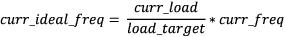
• curr_ideal_freq is the VIC frequency, in Hertz, that would yield a curr_load value of load_target under current instantaneous operating conditions.
• avg_target_freq is the moving average of the target frequency, in Hertz. It is used to avoid abrupt changes in curr_freq when it is recalculated. This property is described more fully in To customize VIC DVFS with control knobs.
Sysfs Paths for DVFS Control
This section describes the use of several knobs that control the operation of VIC DVFS.
Pathnames of Sysfs Nodes for DVFS Control
The sysfs nodes that control VIC knobs are located in a pair of directories whose locations are platform-dependent. The descriptions that follow use these placeholders to represent those directories:
• For NVIDIA Jetson Xavier™ NX, Jetson AGX Xavier series, and Jetson TX2 series:
• <knobpath> represents:
/sys/devices/13e10000.host1x/15340000.vic/
• <knobpath_devfreq> represents:
/sys/devices/13e10000.host1x/15340000.vic/devfreq/15340000.vic/
• For NVIDIA® Jetson Nano™ devices and Jetson™ TX1:
• <knobpath> represents:
/sys/devices/50000000.host1x/54340000.vic/
• <knobpath_devfreq> represents:
/sys/devices/50000000.host1x/54340000.vic/devfreq/54340000.vic/
In the following procedures, replace these placeholders with the appropriate pathnames for your Jetson platform.
VIC DVFS Control Terminology
Many of the control knobs concern the current load and the load target. The default load target is 700, i.e. wmark_active tries to keep the VIC active cycle at 70% of the current VIC frequency.
A lower load target makes VIC frequency scaling more aggressive, because the VIC frequency scales up to Fmax when the VIC active cycle exceeds (load target / 1000) × Fmax.
To enable or disable VIC DVFS
• To enable or disable VIC DVFS, enter the command:
$ echo <gov> > <knobpath_devfreq>/governor
Where <gov> is the name of the VIC devfreq governor to be used:
• To enable VIC DVFS, wmark_active
• To disable VIC DVFS, userspace
VIC DVFS is enabled by default.
For example:
• To disable VIC DVFS on a Jetson Xavier NX series platform, enter:
$ echo userspace > /sys/devices/13e10000.host1x/15340000.vic/devfreq/15340000.vic/governor
• To enable VIC DVFS on a Jetson Nano platform, enter:
$ echo wmark_active > /sys/devices/50000000.host1x/54340000.vic/devfreq/54340000.vic/governor
To customize VIC DVFS with control knobs
• The block_window control knob defines the shortest period between VIC frequency scaling operations, in microseconds. VIC actmon skips frequency scaling if the last VIC frequency scaling operation was performed less than block_window microseconds ago.
To set block_window, enter the command:
$ echo <period> > <knobpath>/block_window
Where <period> is the block_window value to set.
• The load_target control knob sets the VIC load target. To set load_target, enter the command:
$ echo <target> > <knobpath>/load_target
Where <target> is the load target to set.
• The freq_boost_en control knob enables or disables the frequency boost feature. If frequency boost is enabled, wmark_active boosts the VIC frequency to Fmax when the VIC load level exceeds the frequency boost threshold (set by the load_max control knob, below).
To enable or disable frequency boost, enter the command:
$ echo <b> > <knobpath>/freq_boost_en
Where <b> is 1 to enable frequency boost, or 0 to disable it.
• The load_max control knob sets the frequency boost threshold. wmark_active boosts the VIC frequency to Fmax when the VIC load level exceeds the frequency boost threshold. Its range is [0, 1000]. Its default value is 900.
Note that wmark_active boosts the VIC frequency only if freq_boost_en (above) is enabled.
To set the frequency boost threshold, enter the command:
$ echo <max> > <knobpath>/load_max
Where <max> is the frequency boost threshold to set.
• curr_ideal_freq is the VIC frequency, in Hertz, that would yield a curr_load value of load_target under current instantaneous operating conditions.
• avg_target_freq is the average target frequency, in Hertz. That is, it is a moving average of the target frequency, in Hertz.
The smooth knob adjusts the weights that avg_target_freqprevious and curr_ideal_freq are given in adjusting the value of avg_target_freq toward the target frequency.

If smooth is 0, the weight of avg_target_freqprevious is 0% and the weight of curr_ideal_freq is 100%, so avg_target_freqcurrent is set to curr_ideal_freq each time it is adjusted.
To set smooth, enter the command:
$ echo <value> > <knobpath>/smooth
Where <value> is the value to set.
To set the static VIC frequency
For debugging or power/performance evaluation, you may want to set the VIC frequency to a fixed value. You can set the static VIC frequency directly if you disable VIC DVFS.
1. Disable VIC runtime PM (power management) suspend. This forces the VIC hardware block into a power-on state so that you can configure the VIC frequency with commands:
$ echo on > <knobpath>/power/control
2. Read the runtime status.
$ cat <knobpath>/power/runtime_status
The command should display a runtime status of active.
3. Disable VIC DVFS:
$ echo userspace > <knobpath_devfreq>/governor
4. Check the available VIC frequency settings:
$ cat <knobpath_devfreq>/available_frequencies
The command lists the available frequencies like this:
115200000 268800000 409600000 550400000 691200000 844800000 985600000 1036800000
5. Choose one of the available frequencies, and set the VIC maximum frequency and the VIC frequency to that value:
$ echo <frequency> > <knobpath_devfreq>/max_freq
$ echo <frequency> > <knobpath_devfreq>/userspace/set_freq
6. Enable VIC runtime PM suspend:
$ echo auto > <knobpath>/power/control
Configuring Clocks
In general, each block or module has a dedicated clock source register. For detailed information about a given register, see CLK_RST_CONTROLLER_CLK_SOURCE_<module_name> in the Technical Reference Manual (TRM).
Clock source registers provide clock source selection and clock divider control for the module. The divider is typically 8 bits, 7 integer bits and 1 fractional bit (U7.1).
To change clock configurations in the kernel device driver module
1. Declare clocks in Device Tree. For example, for padctl-uphy, clocks can be declared as follows:
clocks = <&tegra_car TEGRA210_CLK_HSIC_TRK>,
<&tegra_car TEGRA210_CLK_USB2_TRK>,
<&tegra_car TEGRA210_CLK_PLL_E>;
clock-names = "hsic_trk", "usb2_trk", "pll_e";
2. Use the devm_clk_get function to obtain the desired clock source using clock-names.
3. Use the clk_get_parent function to obtain the parent clock for the desired clock.
4. Use the clk_set_parent function to select the specified clock source for the target clock.
5. Use the clk_set_rate function to set the frequency of the target clock.
The divider is calculated automatically according to the target rate. Successful clock frequency settings must meet the available divider of that module and the frequency of the clock source.
6. Use the clk_round_rate function to get the exact clock frequency that can be configured from the current clock source.
7. Use clk_prepare_enable (or clk_prepare and clk_enable) functions to ungate/enable the clock. The clk_prepare function can be used instead of clk_enable to ungate a clock if the operation may sleep.
To use PLLAON as clock source
Applies to: Jetson Xavier NX series and Jetson AGX Xavier series only
By default, the PLLAON clock is disabled on T194 L4T platforms to conserve power.
You may want to enable PLLAON to achieve a higher clock rate or more accuracy in certain use cases like CAN and PWM. You can do this by first adding PLLAON as a possible parent of a clock, then setting the parent of the clock to PLLAON.
You make these changes by modifying the BPMPFW DTB and kernel DTB files. The BPMPFW DTB holds the configuration for clocks; the kernel DTB contains the setting that enables and disables PLLAON.
Taking the CAN use case as an example, follow these steps to add PLLAON as a possible parent:
1. Convert the BPMPFW DTB (e.g. tegra194-a02-bpmp-p2888-a04.dtb) to a DTS using the dtc tool.
2. Edit the DTS file to add the PLLAON clock ID to the list of possible parents.
In the DTS file under clocks, add the clock ID for PLLAON (symbol CLK_PLLAON, decimal 94, hex 0x5e), to the allowed-parents list:
clocks {
clock@can1 {
clk-id = <9>; /* confirming TEGRA194_CLK_CAN1*/
allowed-parents <nn,nn,nn,...,94>; /*TEGRA194_CLK_PLLAON*/
};
...
};
This allows PLLAON to be set as parent of CAN1.
3. Convert the DTS file back to DTB.
4. Convert the kernel DTB (e.g, tegra194-p2888-0001-p2822-0000.dtb) to a DTS file using the dtc tool, or obtain the kernel’s source DTS file.
5. Edit the kernel DTS file to make CAN use PLLAON as parent and remove PLLAON (entry 0x4 0x5e) from the list of clocks to be disabled:
clocks-init{
compatible = "nvidia,clocks-config";
disable {
/* Edit clocks property to remove clock provider + clock id pair for PLLAON. */
clocks = <nn nn, nn nn,...>;
};
};
6. To change the mttcan node to select PLLAON as parent, add "pllaon" to the list in clock-names, and add an entry for 0x4 0x5e to the list in clocks:
mttcan@c310000 {
pll_source = "pllaon";
clocks = <..., 0x4 0x5e>; /*New entry*/
clock-names = <name>, <name>, <name>, ..., "pllaon";
};
7. Convert the DTS file to DTB, or build the kernel DTB if you edited the source files.
8. Flash the board with the modified DTB files.
Clocks that Can Have PLLAON as Parent
The following clocks can be configured to have PLLAON as a parent:
• TEGRA194_CLK_CAN1
• TEGRA194_CLK_CAN2
• TEGRA194_CLK_DMIC5
• TEGRA194_CLK_I2C2
• TEGRA194_CLK_I2C8
• TEGRA194_CLK_PWM4
• TEGRA194_CLK_SPI2
• TEGRA194_CLK_UARTG