NVLink Switch Planning and Design#
Confirm Accurate Hardware Models and Quantities#
Kubernetes Admin|User nodes server (3x)
NVLink Switches (non-scaleout) (x9 per rack)
Transceivers (optical) and cables (DAC / AOC)
Fiber and Copper cables
Network and Connectivity Requirements#
Kubernetes Admin|User nodes to BTOR switch connectivity#
Transceiver type, compatibility and HW order status
Electrical signaling/encoding (NRZ vs PAM4)
Speed/Bandwidth
IP Addressing
Logical Connectivity (Access and Bonded).
NVLink Switch to OOB Switch connectivity#
Copper connections
Speed/Bandwidth
IP Addressing
Logical Connectivity (Access)
Routable IP Address Allocation#
Kubernetes Admin|User nodes server will have IP addresses allocated from Inband and OOB (ComE0) subnets.
NVSwitches will have IP addresses allocated from OOB (ComE0) subnets.
Kubernetes Admin|User nodes and NVLink Switch Connectivity - To provision and manage NVLink Switch/NVLink.
Use Default Partition
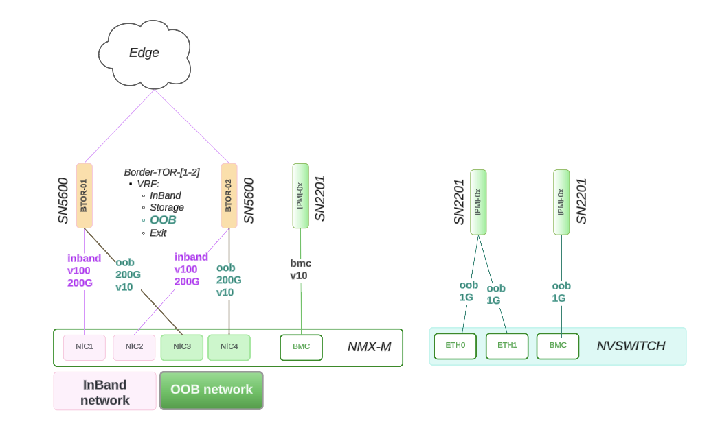
Figure 14 NVLink Switch Connectivity#
NVLink Switch Design#
This section describes the NVLink Switch design and connectivity.
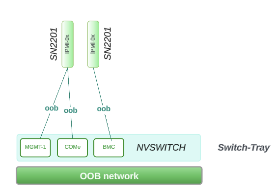
Figure 15 NVLink Switch Design#
Physical Connectivity
Reference Design - Connectivity
ComE1: 1G connects to within Rack Switch: SN2201 on RU 45
ComE2: 1G connects to within Rack Switch: SN2201 on RU 45
BMC: 1G connects to within Rack Switch: SN2201 on RU 44
Network Allocation Breakout
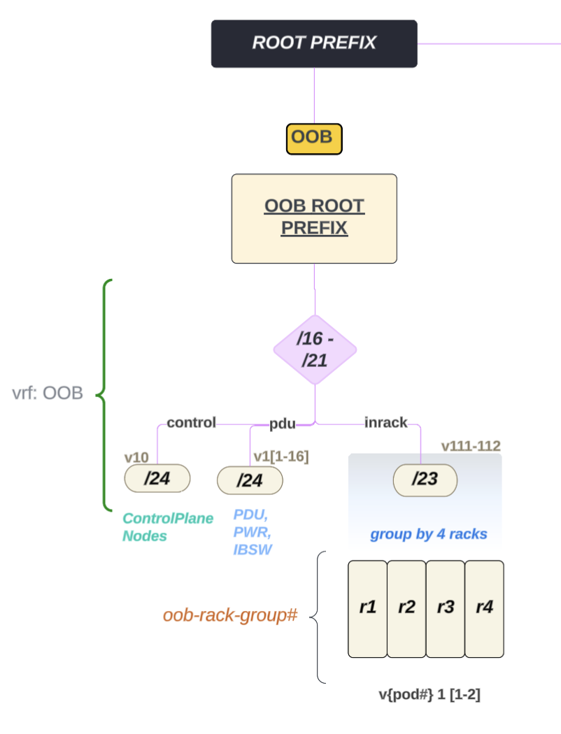
Figure 16 NVLink Switch Network Allocation Breakout#
ComE1, ComE2, BMC are part of the same larger OOB subnet which covers 4 x GB200 racks
NVLink Switch Integration with BCM Verification#
The following image describes the workflow of the NVLink Switch Integration with BCM verification:
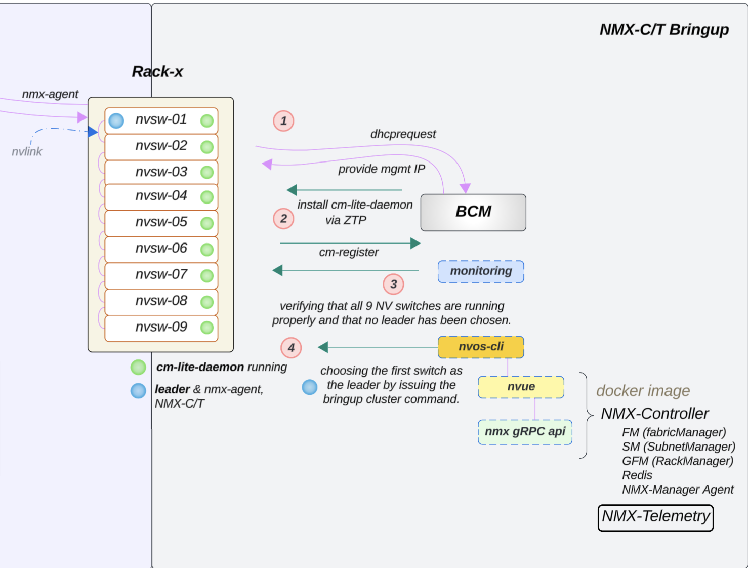
Figure 17 NVLink Switch Integration with BCM Verification#
NVLink Switch Tray Check and Configuration#
Note
If the NVLink Switch is running a version earlier than 25.02.2134, the custom script and cm-lite-daemon will not be installed. However, once the switch is upgraded to a newer version through ZTP, it will recognize the custom script option and install the cm-lite-daemon.
This process will take approximately 2 to 4 minutes longer than a standard ZTP.
To check the NVLink Switch configuration, follow the steps below:
Confirm OOB power control of the NVLink Switches using a power status check in BCM, like what was done for a GB200 compute tray.
Verify that an NVLink Switch can be reached using SSH from the head node through the admin user. The password may have been initially set during the bcm-netautogen process. A typical password is admin.
ssh admin@<rack location>-NVSW-01
Set the password to match what has been put into BCM for the NVLink Switch entry under accesssettings.
Verify that the NVLink Switch parameter settings are correct.

Figure 18 NVLink Switch Parameter Settings#
Then check the ZTP settings: cmsh > device > use <nvswitch> ztpsettings
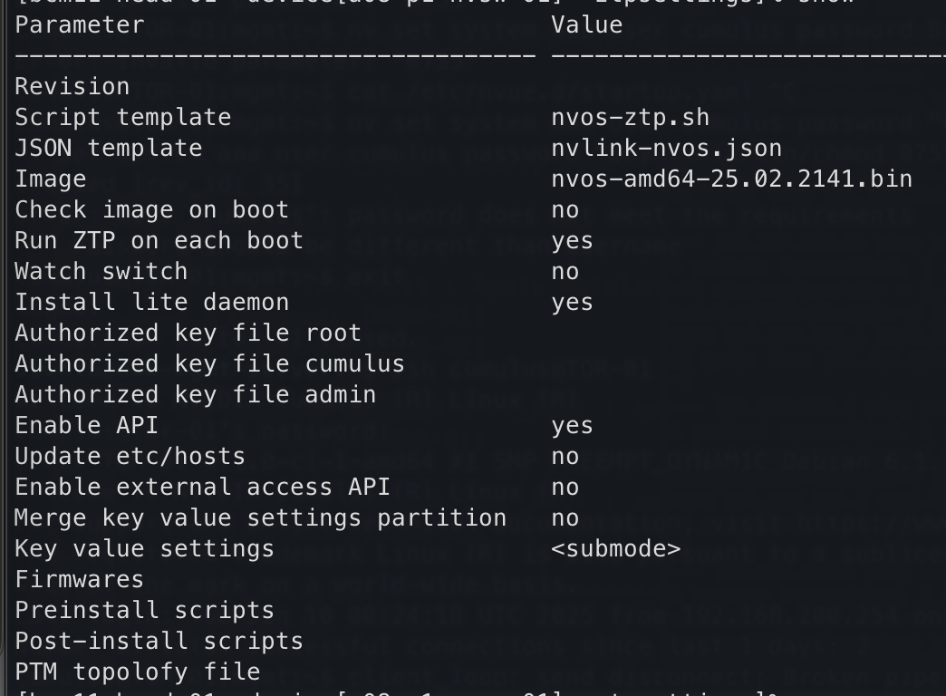
Figure 19 NVLink Switch ZTP Settings#
To verify the settings of the NVLink Switch Configuration:
If the NVLink Switch comes pre-installed with NVOS from the factory and the factory password has already been reset, NVOS Zero Touch Provisioning (ZTP) will be disabled. NVOS-ZTP script will be executed once the device is reachable.
Reset NVSwitch System to factory reset:
nv action reset system factory-default force
NVSwitch will reboot automatic (takes ~2.3mins)
Wait for the switch to come up automatically.
On the backend, the following things will happen:
The
nvlink-nvos.jsonfile is pulled and then the system:Validate the format and create folders defined in the section
/var/lib/ztp/sections.
Each section is iterated through section by section and the following actions performed:
Verify Network Connectivity
Upgrade NVOS Image
Adjust Security Settings by setting password hardening to disabled.
Apply generated startup.yaml and patch configuration
Execute nvos-ztp.sh script to install
cm-lite-daemonThis action will initiate the following actions:
Pulls packages from BCM
Register certs with BCM
Enables the service
Once all the NVLink Switches are up within the rack, the system begins the (auto) leader selection process
Out of the 9, select 1 nvswitch and apply
fm_configand then enable the cluster.
NVLink Switch Workflow Diagram:#
NVSWITCH - FIRMWARE Upgrade process is separate, not part of ZTP
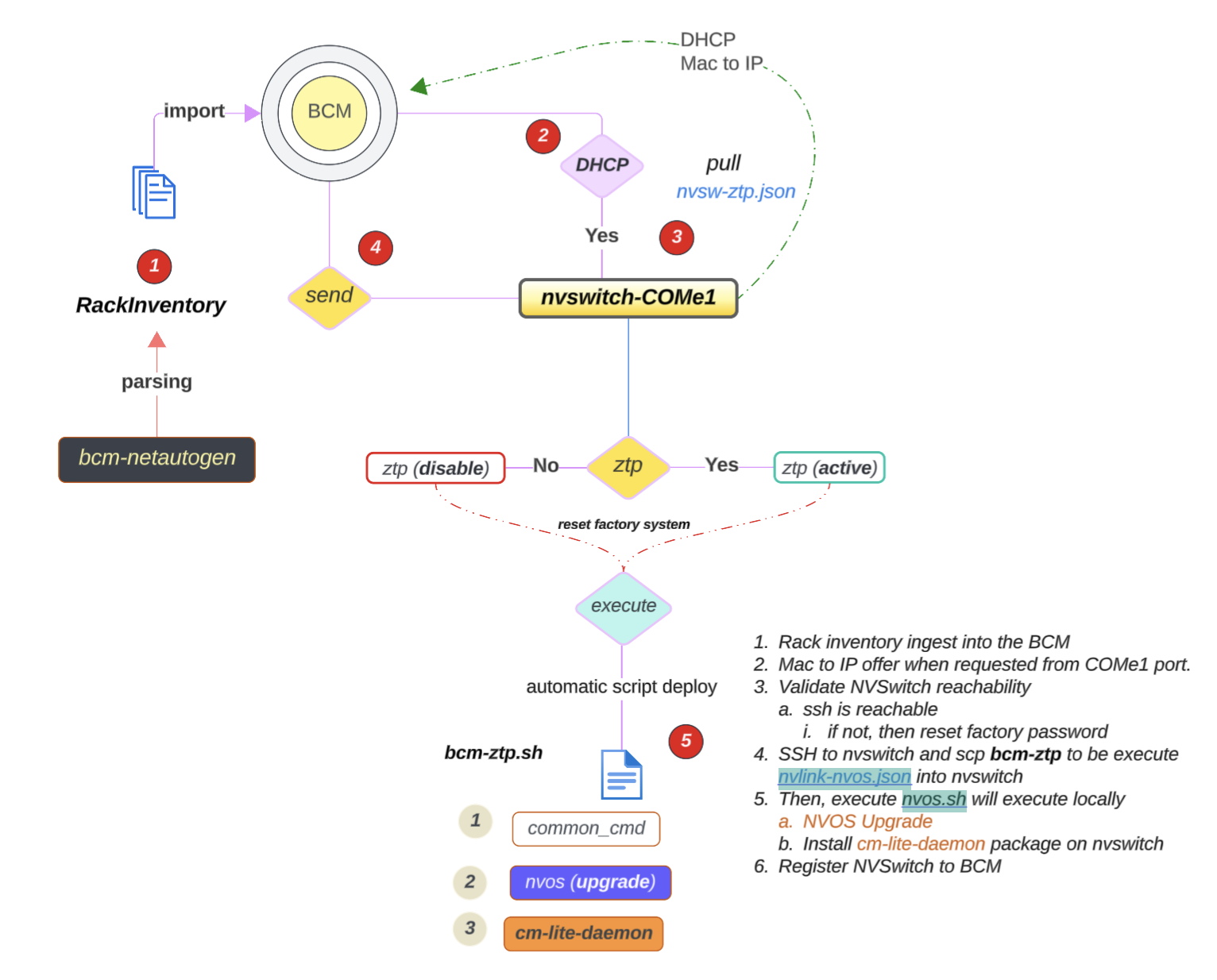
Figure 20 NVLink Switch Workflow Diagram#