Configure Cluster Ethernet Networking#
Summary#
This document provides comprehensive guidance for configuring Ethernet networking in GB200 cluster deployments. It covers the complete workflow from factory preparation through field deployment, including both automated and manual configuration approaches.
Key Topics Covered:
Network Architecture: Configuration of five primary network types - Edge, BCM Inband (Control Plane), DGX Storage, OOB (SN2201), and NVSwitch COMe networks
USB Preparation: Setup requirements for bootable BCM ISO and deployment tools
Rack Inventory Workflow: End-to-end process from factory preparation through data collection, cable mapping, and BCM configuration
Manual Configuration: Step-by-step guidance for 1-2 rack setups including IP subnet planning and switch provisioning
Deployment Options: Two primary approaches - manual USB-based provisioning and automated Zero Touch Provisioning (ZTP) through BCM
Switch Configuration: Detailed procedures for Cumulus Linux switches using NVUE commands and startup.yaml files
Access OOB Setup: Special configuration requirements for the initial out-of-band management switch
The following files are required. These can either be created manually or formatted automatically.
For each network that is setup within BCM there is an equivalent set of physical switches that need to be deployed and configured:
(edge) - Edge Network
(internalnet) - BCM Inband Network Switch - Control Plane/Internalnet
(storagenet) - DGX Inband/Storage Network Switches
(ipmninet0) - OOB Network (SN2201)
(ipminet(n) - NVSwitch COMe Network, PDU/Power Shelves, IB Switches, In Rack OOB
Refer to the M0 document for pre-work that needs to be done before deploying the configuration per switch type above.
USB Preparation#
To prepare the USB sticks for the deployment:
Prepare 2 USB (~size: 64gb) sticks:
USB #1: Bootable BCM ISO
- USB #2:
Cumulus OS (.bin), NVOS (.bin), Infiniband Switch OS (.img)
p2p_ethernet.csv, siteinfo.yml (See the Appendix: Configuration Examples for examples).
GB200 Rack Inventories Workflow#
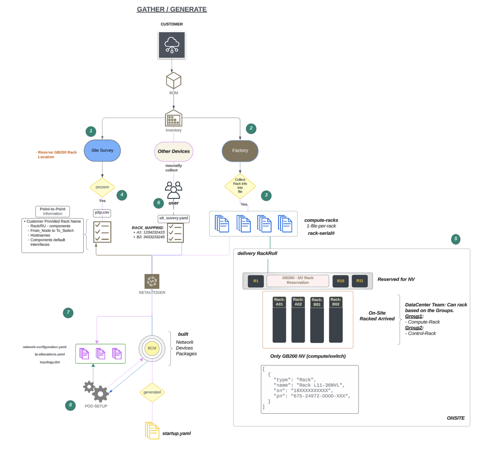
Figure 2 GB200 Rack Inventories Workflow#
The GB200 Rack Inventories Workflow is as follows:
Factory Preparation: Prepare the racks at the factory.
Data Collection: The factory collects data for each rack’s components and sends an Excel file for each rack.
Cable Mapping: Prepare point-to-point (P2P) files for cable mapping.
Rack Arrival: Receive racks from the factory (not necessarily in order). Placement: Roll the GB200 racks into the reserved locations as they arrive.
Parser: Will parse the rack inventory file and create mac to IP allocation (Check with NVIS Team)
Rack Identification: Update identifies the rack serial numbers and maps them to rack names in the site survey file, along with other SuperPOD build information.
Mapping Format:
<CUSTOMER_RACK_POSITION_NAME>: <RACK_SERIAL_NUMBER>Netautogen Tool: Run the netautogen tool.
File Retrieval: Pull the P2P file and the site survey data, including the rack mapping, network details, and other information.
Data Processing: This tool identifies data based on rack name mapping and retrieves serial numbers, interface names, and MAC addresses for each component
Data Generation: Generate data for each component, including IP addresses, serial numbers, MAC addresses, and interfaces.
BCM Configuration: Add configuration to BCM with the network, devices, and packages.
Manual Process#
This section provides general guidance for 1-2 rack setup only. It does not include all the steps involved to configure the entire fabric manually.
The following table shows the workflow for manual set up of the rack:
STAGES |
SUMMARY |
STATUS |
|---|---|---|
1 |
Preparation and Documentation |
|
2 |
On-Site Validation and Testing |
|
3 |
Zero Touch Provisioning (ZTP) Readiness |
|
Stage1: Preparation: Build IP breakout#
For stage 1, the IP breakout is built as follows:
GB200:#
The minimum subnet calculation for 4 full GB200 racks is as follows:
Number of Switches
POD |
RACKs |
GPUs |
DGX Systems |
CPU |
|---|---|---|---|---|
1 |
8 |
576 |
144 |
10 |
2 |
16 |
1152 |
288 |
10 |
3 |
24 |
1728 |
432 |
10 |
4 |
32 |
2304 |
576 |
10 |
OOB Subnet Breakouts
OOB Networks |
Configuration 1 |
Configuration 2 |
|---|---|---|
ipminet1 |
2 x /24 |
1 x /23 |
ipminet1[1-16] |
2 x /24 |
2 x /23 |
ipminet2[1-16] |
2 x /24 |
3 x /23 |
2 x /24 |
4 x /23 |
DATA Subnet Breakouts
OOB Root Prefix |
DATA Root Prefix |
Root Prefix Size |
internalnet |
MISC (Lo0/Edge) |
dgxnet1[1-n] |
|---|---|---|---|---|---|
1 x /24 |
1 x /24 |
2 x /25 |
21 |
22 |
20 |
1 x /24 |
1 x 24 |
4 x /25 |
21 |
22 |
20 |
1 x /24 |
1 x 24 |
6 x /25 |
21 |
21 |
20 |
1 x /24 |
1 x 24 |
8 x /25 |
21 |
21 |
20 |
Switch Configuration using Template:#
For efficiency, reference Cumulus NVUE commands for OOB, TOR, and SPINE are provided in the Appendix: Configuration Examples section.
Once the switch configurations are prepared, copy the configuration on to USB #2 by following the steps below:
Download the Cumulus Linux Installer Binary.
Go to the Nvidia Enterprise Portal and browse to: Downloads > Switches and Gateways > Switch Software > Nvidia Cumulus Linux to download the Cumulus Linux Installer Binary.
Prepare the USB Installation Media (see USB Preparation).
Stage 2: ON Field Deployment#
Option 1: To provision the Ethernet Switch manually#
Use the following steps to provision OS manually using a USB stick:
Connect USB #2 to the Cumulus Switch.
Power cycle the switch.
Required USB-C to RJ45
Connect the USB-C into the laptop (MAC) and the RJ45 to the console port of the Switch.
Console into the Switch:
If you are using macOS, then the following command can be used:
ls /dev/cu.*, and look for something like usbserial
screen /dev/cu.usb 115200
If NVUE commands created, then just copy and paste directly to the command line:
nv config show
nv config diff
nv config apply -y
If you have prepared startup.yaml file, then do following:
## Copy the startup.yaml
cp /media/BCM/<hostname>_startup.yaml /etc/nvue.d/startup.yaml
nv config replace /etc/nvue.d/startup.yaml
nv config apply -y
Disconnect USB #2 and Console cable (RJ45) from the switch.
Repeat Step 1 to all the Cumulus Ethernet Switches.
Option 2: Provision your Ethernet Switch using BCM through the ZTP process#
If you are following the second option, ZTP provisioning the ethernet switch using BCM:
Insert USB#2 into the BCM.
Ensure USB#2 contains the pre-generated and/or modified configuration files.
Copy the content from the USB# 2 into BCM
Connect the USB# 2 into BCM and then use the following command sequence:
sudo fdisk -l
sudo mkdir -r /media/BCM
sudo mount -t vfat /dev/sdb1 /media/BCM
lsblk
sudo rsync -av /media/BCM/*.bin /cm/local/apps/cmd/etc/htdocs/switch/image
sudo rsync -av /media/BCM/* <any local path>
Use the configuration tailored to the Customer Project.
Copy the Cumulus switch configuration files from USB#2.
Transfer startup.yaml to the following directory:
/cm/local/apps/cmd/etc/htdocs/switch/<hostname>/startup.yaml.
Choose your option:#
Whether you want bcm-netautogen to be run or not, you can choose your option by following the steps below:
NO bcm-netautogen, YES bcm-pod-install:#
If the BCM is operating on an ARM64 architecture, an additional ISO image named <name>_x86.iso must be mounted. This ISO contains the cm-lite-daemon package, which is required for installation on Cumulus, and NVOS systems.
Upload bcm_x86.iso on to BCM by running the following commands:
mount -o loop <file_name_bcm_x86.iso> /mnt/dvd/
cd /mnt/dvd/data
cm-lite-daemon-repo /mnt/dvd/

## File will be copied over here:
ls -l /cm/local/apps/cmd/etc/htdocs/switch/ | grep cm-lite
bcm-pod-setup -I /root/bcm-<image>.iso -C 100.126.0.0/16 -S 100.127.0.0/16 --dgx-type gb200
Note
When adding flag --dgx-type gb200 (the tool bcm-netautogen was not executed).
Since bcm-netautogen was not run, the dgx-type value is instead taken from siteinfo.yaml.
NO bcm-netautogen, NO bcm-pod-install#
CM-Create IMAGE
Upload the DGX Image required pre-existing image (/cm/image/<dgx_image>)
Depending on the Airgapped Environment, run the following commands:
Airgapped Environment
adding --skipdist (not to update the apt-get package)
cm-create-image -n dgx-os-7.1-gb200-image -a /root/baseos7.1-image-arm64-04-25-2025.tar.gz --dgx -r --no-cm-cuda-repo --cmdvd /root/bcm-11.0-ubuntu2404-dgx-os-7.1.iso --skipdist
Non-Airgapped Environment
- CREATE IMAGE REQUIRED
To Download the .tar file https://support2.brightcomputing.com/baseos7-<ARCH>/<latest>.tar.gz
cm-create-image -n dgx-os-7.1-gb200-image -a baseos7.1-image-arm64-04-25-2025.tar.gz -s --dgx -r --no-cm-cuda-repo --cmdvd bcm-11.0-ubuntu2404-dgx-os-7.1.iso
Configure manually following features:
Network
cmsh network; list
add ipminet0
set netmaskbits 26
set baseaddress <subnet network>
set nodebooting yes
set dynamicrangestart <network start range>
set dynamicrangeend <network end range>
set gateway <subnet gw>
set type Internal
set domainname cm.ipminet1
exit
commit
switch:
add switch <switch_hostname>
set ip <ipv4address>
set network ipminet0
set mac <provide correct mac>
set nvconfigurationmode file
set nvconfigurationfile <file path of switch configuration>
set hasclientdaemon yes
set disablesnmp yes
ztpsettings
set enableapi yes
set checkimageonboot yes
set image cumulus-linux-<version>-mlx-amd64.bin
exit
commit
The following images show examples of the switch settings:

Figure 3 NV configuration example output#
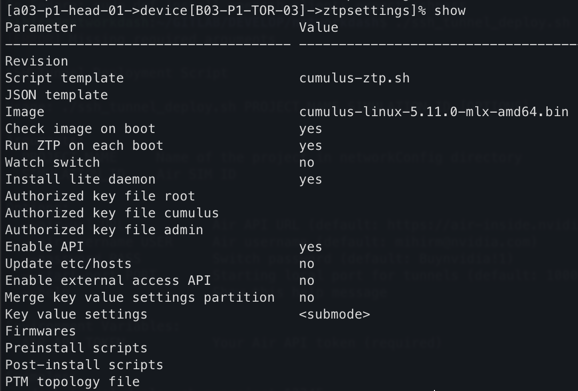
Figure 4 ZTP Settings (command-line output) example output#
Initiate Primary OOB Cumulus Linux Switch Provisioning.
Connect USB-to-Serial Install/Upgrade Cumulus Linux.
Apply Configuration.
Upload the startup.yaml
Copy the content to
/etc/nvue.d/startup.yaml.
nv config replace /etc/nvue.d/startup.yaml
nv config apply -y
Once the Access-OOB is configured, all ETH0 interfaces should be connected to the Access-OOB network. Based on the modified startup configuration placed in the designated BCM location, ZTP will automatically apply the configuration and install the cm-lite-daemon as part of the Cumulus ZTP process.
Set up the Access OOB Switch#
What is an Access OOB Switch? It refers to an SN2201 OOB switch connected to an additional BCM RJ45 1G cable. Its purpose is to provision the first OOB switch, which is typically where most of the core Ethernet switch management connections are made.
Build the Access-OOB switch before provisioning other switches. The following image shows an example of the Access-OOB switch:
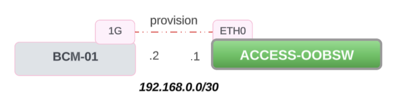
Figure 5 Access OOB Switch#
Check if there is a 1G cable connected to OOB SW ETH0 port by running the following command:
cmsh -c "network; add provision; set domainname provision.cluster; set baseaddress 192.168.0.0; set netmaskbits 30; set nodebooting yes; set dynamicrangestart 192.168.0.1; set dynamicrangeend 192.168.0.1; commit"
If there is 1G cable connected, a new network named “provision” will be created in the BCM with the network address
192.168.0.0/30.Reboot the Access-OOB switch:
The rebooted switch will receive
192.168.0.1IP from the BCM and it will configure thestartup.yamlfile.