Networking Planning and Design#
Network architecture planning for GB200 and GB300 systems following the SuperPOD reference design framework. The majority of networking requirements are comprehensively addressed in the Ethernet reference documentation. The SuperPOD reference design for GB200/GB300 adopts an EVPN Multihoming VXLAN architecture with Head-End Replication for North-South networking, leveraging symmetric routing for optimal traffic flow. Additional supporting information is provided in this document.
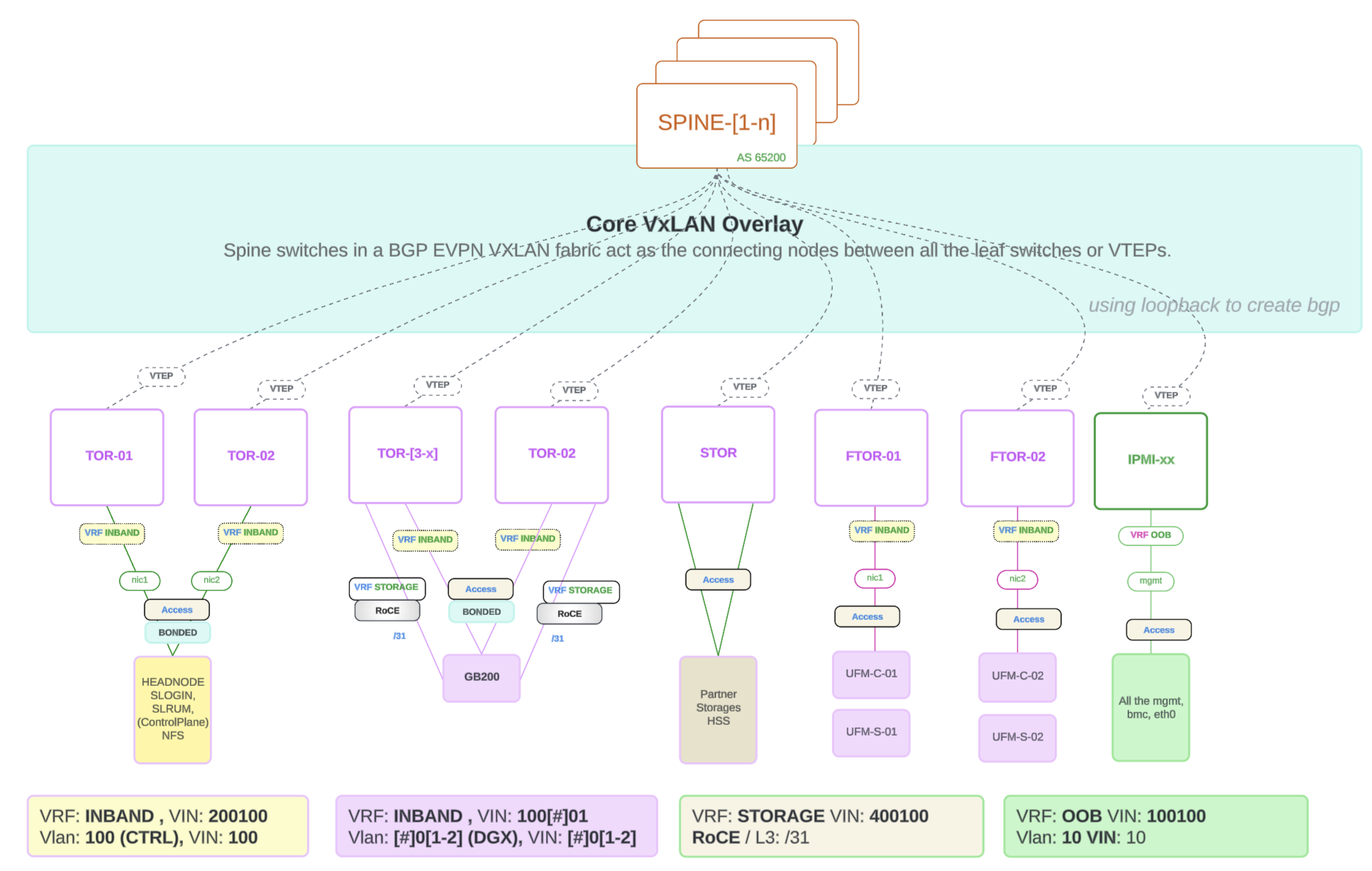
Figure 3 GB200/GB300 EVPN w/ Head-End Replication#
EVPN Symmetric routing with Cumulus Linux: Each VTEP automatically uses a unique MAC address by default.
Pros |
Cons |
|---|---|
Simple — each VTEP uses its own MAC. No coordination required for a shared address. Easier to troubleshoot per-node traffic. |
When a host MAC moves (e.g. failover), remote VTEPs must update their MAC tables for the new VTEP’s MAC. |
North-South Ethernet Networking#
IP subnet range/CIDR requirements as defined by BCM network naming conventions. Applicable to both GB200 and GB300.#
Network |
IP Range Requirement |
|---|---|
Routable IP Ranges |
|
InBand Mgmt |
internalnet: Control Plane Data, dgxnet[1-n]: DGX |
Out of Band (OOB) |
ipminet[1-n]: IPMI |
Loopback |
/24 - to cover address from each switches |
Client P2P IP Addressing (TOR to CE) (Border TOR to EDGE Network) |
/31 - cross connect |
Non-Routable IP Range |
|
ETH Storage Network |
100.127.0.0/16 |
IB Compute Network |
100.126.0.0/16 |
Vendor Storage Prefix |
100.127.124.0/24 |
BGP ASN 4-Byte Range (internal within SuperPod) |
|
OOB |
4294902361 - 4294902460 |
TOR/STOR |
4294902461 - 4294902660 |
SPINEs / SuperSPINEs |
4294902661 - 4294902750 / 4294902751 - 4294902760 |
GB300 Subnetting Breakout#
The following figure shows the GB300 subnetting breakout scheme. A single ROOT PREFIX is divided into an OOB (Out-of-Band) branch and a DATA branch, each with its own VRF and subsequent subnet allocations.
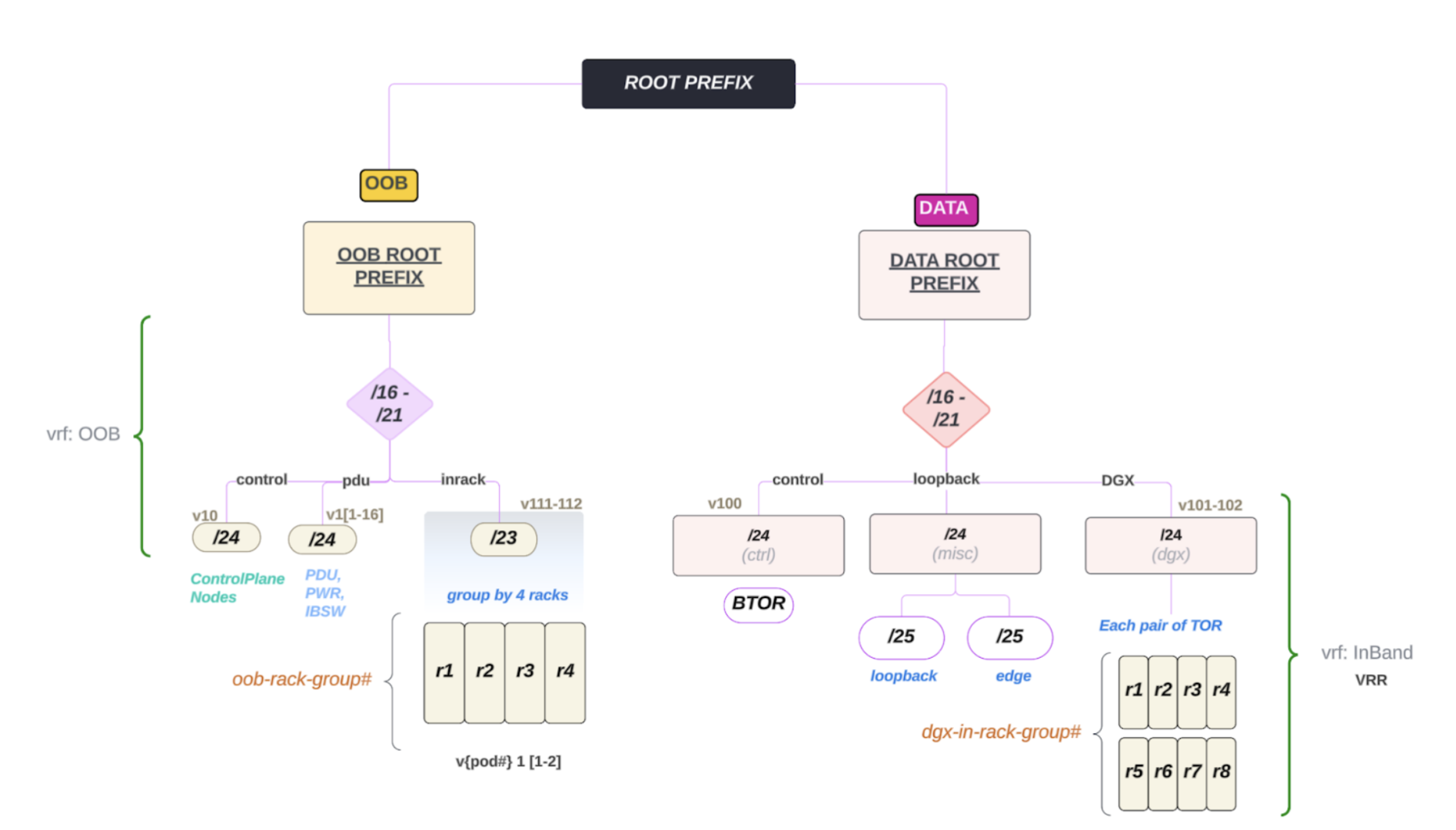
Figure 4 GB300 subnetting breakout scheme#
OOB (VRF: OOB) — Root range /16–/21:
Control (v10) — /24 for Control Plane nodes.
PDU (v1[1-16]) — /24 for PDU, PWR, and IBSW (in-band switch) management.
Inrack (v111–112) — /23 for in-rack OOB; grouped by 4 racks per OOB rack group (
oob-rack-group#). Pod labeling:v{pod#} 1 [1-2].
DATA (VRF: InBand VRR) — Root range /16–/21:
Control (v100) — /24 (ctrl) for BTOR (Backbone/Border Top-of-Rack) control plane.
Loopback (v101–102) — /24 (misc) with /25 for loopback and /25 for edge.
DGX (v101–102) — /24 (dgx) for DGX connectivity; each pair of TOR serves a group of racks. Racks are grouped as
dgx-in-rack-group#(e.g., r1–r4 and r5–r8 per pair of TOR).
Use this scheme when planning IP allocation and rack grouping for GB300 deployments.
Ethernet Planning#
This section provides a comprehensive guide for planning and designing the Ethernet networking for the GB200/GB300 SuperPOD.
Confirm Accurate Hardware Models and Quantities#
Ethernet switches x amount of SN5600
Transceivers (optical) and cables (DAC / AOC)
Required NVLink Switch (NVOS) Version#
Current Recommended version - 23.02.0956
Confirm Required Cumulus Linux Software Version#
Current Recommended version - v5.14.0
Obtain Customer Network Requirements#
Content/Consideration List#
Customer-Edge to Cluster connectivity
Transceiver type, compatibility and HW order status
Electrical signaling/encoding (NRZ vs PAM4)
Speed/Bandwidth
Uplink Quantity (transceiver, cable, fiber)
IP Addressing - P2P Uplinks
Routing protocol (default: BGP)
EVPN Planning Stage#
VLAN VNI Per TOR Pair
DGX Compute (InBand) VLAN#
POD# |
DGX Compute VLANs |
Compute VNI |
|---|---|---|
POD#1 |
101,102 |
101,102 |
POD#2 |
201,202 |
201,202 |
POD#3 |
301,302 |
301,302 |
POD#4 |
401,402 |
401,402 |
POD#5 |
501,502 |
501,502 |
POD#6 |
601,602 |
601,602 |
POD#7 |
701,702 |
701,702 |
POD#8 |
801,802 |
801,802 |
POD#9 |
901,902 |
901,902 |
POD#10 |
1001,1002 |
1001,1002 |
POD#11 |
1001,1002 |
1001,1002 |
POD#12 |
1201,1202 |
1201,1202 |
POD#13 |
1301,1302 |
1301,1302 |
POD#14 |
1401,1402 |
1401,1402 |
POD#15 |
1501,1502 |
1501,1502 |
POD#16 |
1601,1602 |
1601,1602 |
OOB VLAN / VNI#
POD# |
OOB VLAN |
Compute VNI |
|---|---|---|
POD#1 |
111,112 |
111,112 |
POD#2 |
221,222 |
221,222 |
POD#3 |
331,332 |
331,332 |
POD#4 |
441,442 |
441,442 |
POD#5 |
551,552 |
551,552 |
POD#6 |
661,662 |
661,662 |
POD#7 |
771,772 |
771,772 |
POD#8 |
881,882 |
881,882 |
POD#9 |
991,992 |
991,992 |
POD#10 |
1011,1012 |
1011,1012 |
POD#11 |
1111,1112 |
1111,1112 |
POD#12 |
1221,1222 |
1221,1222 |
POD#13 |
1331,1332 |
1331,1332 |
POD#14 |
1441,1442 |
1441,1442 |
POD#15 |
1551,1552 |
1551,1552 |
POD#16 |
1661,1662 |
1661,1662 |
VRF Configuration#
VRF Type |
VNI |
VLAN ID |
|---|---|---|
OOB |
10010 |
1001 |
Inband |
200100 |
2001 |
Storage |
400100 |
Cluster Route Advertisement and External Reachability#
Cluster Route Advertisement and External Reachability is checked for the following components:
BMS Connectivity - Data Center Environment Monitoring
3rd Party Appliance Connectivity Requirements (Storage, etc.)
Physical Connectivity (Type, Speed, etc.)
Logical Connectivity (L2, Bond, L3, etc.)
IP Addressing
Preparation Information Requirements#
The following information is required for the preparation:
Obtain the factory rack inventory file. Refer to Appendix Section 3 for an example.
Coordinate with the factory to generate copies of the serial and MAC address files for racks being shipped.
The rack inventory is essential for mapping MAC addresses to IP allocations; otherwise, this data would need to be collected manually per NIC, which is time-consuming.
“Factory File” Available from Manufacturing Partner
Includes component level MAC/Interface/SN/PN Information:
GB200/GB300 compute tray
NVLink Switch
MGX Rack Power Shelf
SN2201
Gather MACs#
Host: BMC + N/S Provisioning Interfaces
Mgmt Servers (control plane)
UFM Servers
NetQ servers
Switch: Mgmt interface (mgmt. or eth0)
Ethernet
PDUs: Mgmt interface (mgmt. or eth0)
Point-to-Point Cabling Connectivity Plan (Required)