Hardware Installation
Installation and initialization of ConnectX-5 adapter cards require attention to the mechanical attributes, power specifications, and precautions for electronic equipment.
Safety Warnings
InfoSafety warnings are provided here in the English language. For safety warnings in other languages, refer to the Adapter Installation Safety Instructions.
Please observe all safety warnings to avoid injury and prevent damage to system components. Note that not all warnings are relevant to all models.
Note that not all warnings are relevant to all models.

General Installation Instructions
Read all installation instructions before connecting the equipment to the power source.

Jewelry Removal Warning
Before you install or remove equipment that is connected to power lines, remove jewelry such as bracelets, necklaces, rings, watches, and so on. Metal objects heat up when connected to power and ground and can meltdown, causing serious burns and/or welding the metal object to the terminals.
Over-temperature
This equipment should not be operated in an area with an ambient temperature exceeding the maximum recommended: 55°C (131°F). An airflow of 200LFM at this maximum ambient temperature is required for HCA cards and NICs. To guarantee proper airflow, allow at least 8cm (3 inches) of clearance around the ventilation openings.
During Lightning - Electrical Hazard
During periods of lightning activity, do not work on the equipment or connect or disconnect cables.
Copper Cable Connecting/Disconnecting
Some copper cables are heavy and not flexible, as such, they should be carefully attached to or detached from the connectors. Refer to the cable manufacturer for special warnings and instructions.
Equipment Installation
This equipment should be installed, replaced, or serviced only by trained and qualified personnel.
Equipment Disposal
The disposal of this equipment should be in accordance to all national laws and regulations.
Local and National Electrical Codes
This equipment should be installed in compliance with local and national electrical codes.

Hazardous Radiation Exposure
Caution – Use of controls or adjustment or performance of procedures other than those specified herein may result in hazardous radiation exposure.For products with optical ports.
CLASS 1 LASER PRODUCT and reference to the most recent laser standards:
IEC 60 825-1:1993 + A1:1997 + A2:2001 and EN 60825-1:1994+A1:1996+ A2:20
Installation Procedure Overview
The installation procedure of ConnectX-5 adapter card kit with Multi-Host involves the following steps:
Step
Procedure
General Installation Instructions
Read all installation instructions before connecting the equipment to the power source.
Jewelry Removal Warning
Before you install or remove equipment that is connected to power lines, remove jewelry such as bracelets, necklaces, rings, watches, and so on. Metal objects heat up when connected to power and ground and can meltdown, causing serious burns and/or welding the metal object to the terminals.
Over-temperature
This equipment should not be operated in an area with an ambient temperature exceeding the maximum recommended: 55°C (131°F). An airflow of 200LFM at this maximum ambient temperature is required for HCA cards and NICs. To guarantee proper airflow, allow at least 8cm (3 inches) of clearance around the ventilation openings.
During Lightning - Electrical Hazard
During periods of lightning activity, do not work on the equipment or connect or disconnect cables.
Copper Cable Connecting/Disconnecting
Some copper cables are heavy and not flexible, as such, they should be carefully attached to or detached from the connectors. Refer to the cable manufacturer for special warnings and instructions.
Equipment Installation
This equipment should be installed, replaced, or serviced only by trained and qualified personnel.
Equipment Disposal
The disposal of this equipment should be in accordance to all national laws and regulations.
Local and National Electrical Codes
This equipment should be installed in compliance with local and national electrical codes.
Hazardous Radiation Exposure
Caution – Use of controls or adjustment or performance of procedures other than those specified herein may result in hazardous radiation exposure.For products with optical ports.
CLASS 1 LASER PRODUCT and reference to the most recent laser standards:
IEC 60 825-1:1993 + A1:1997 + A2:2001 and EN 60825-1:1994+A1:1996+ A2:20
1
Check the system’s hardware and software requirements.
2
Pay attention to the airflow consideration within the host system.
3
Unpack the product.
4
Install the ConnectX-5 main adapter card in the system.
5
Install the PCIe Auxiliary cards in the system.
6
Connect the mini SAS harnesses or modules to the card.
7
Power Up the card
8
Identify your ConnectX-5 adapter card in the system.
System Requirements
Hardware Requirements
WarningUnless otherwise specified, NVIDIA products are designed to work in an environmentally controlled data center with low levels of gaseous and dust (particulate) contamination.
The operating environment should meet severity level G1 as per ISA 71.04 for gaseous contamination and ISO 14644-1 class 8 for cleanliness level.
A system with four available PCI Express x4 slots is required for installing the ConnectX-5 and card and three PCIe Auxiliary cards.
WarningFor proper operation and performance, please make sure to use a PCIe slot with a corresponding bus width and that can supply sufficient power to your card. Refer to the Specifications section of the manual for more power requirements.
Airflow Requirements
ConnectX-5 adapter card kit is offered with one airflow pattern: from the network ports to the heatsink, as shown below.
Please refer to the "Specifications" chapter for airflow numbers.
Airflow from the network ports to the heatsink:
 Warning
All cards in the system should be planned with the same airflow direction.
Software Requirements
See Operating Systems/Distributions section under the Introduction section.
Software Stacks - NVIDIA OpenFabric software package MLNX_OFED for Linux. See the Driver Installation section.
Unpacking the Product
WarningThe adapter is being installed in a system that operates with voltages that can be lethal. Before opening the case of the system, observe the following precautions to avoid injury and prevent damage to system components.
Remove any metallic objects from your hands and wrists.
Make sure to use only insulated tools.
Verify that the system is powered off and is unplugged.
It is strongly recommended to use an ESD strap or other antistatic devices.
Unpack the adapter package and place them on an antistatic surface, and verify you have received the following items:
ConnectX-5 Adapter Card, with a short bracket assembled on the card.
3x PCIe Auxiliary cards, with a short bracket assembled on each of the cards.
3x Mini-SAS HD cables.
Check the parts for visible damage that may have occurred during shipping.
Shut down your system if active:
Turn off the power to the system, and disconnect the power cord. Refer to the system documentation for instructions. Before you install the ConnectX-5 card, make sure that the system is disconnected from power.
Installation Instructions
This section provides detailed instructions on how to install your ConnectX-5 adapter card kit in your system.
NotePlease note that the following figures are for illustration purposes only.
The ConnectX-5 VPI adapter card kit installation in the system should be planned according to the below figure.

Install the ConnectX-5 main adapter card in the system:

Before installing the card, make sure that the system is off and the power cord is not connected to the server. Please follow proper electrical grounding procedures.
Open the system case.
Applying even pressure at both corners of the card, insert the card into the PCI Express slot until firmly seated.

When the adapter is properly seated, the port connectors are aligned with the slot opening, and the adapter faceplate is visible against the system chassis.

Secure the adapter with the adapter screw.
Install the three PCIe Auxiliary cards in the system:
Applying even pressure at both corners of the card, insert the PCIe Auxiliary cards into the available PCI Express x4 slots until firmly seated.

When the PCIe Auxiliary card is properly seated, the harness connector is aligned with the slot opening, and the PCIe Auxiliary faceplate is visible against the system chassis.

Connect the ConnectX-5 Main Adapter Card with each PCIe Auxiliary Cards using the supplied mini SAS harnesses, as shown in the below figure.
 Info
InfoTo uninstall the adapter card, see Uninstalling the Card.
Cables and Modules
Cable Installation
All cables can be inserted or removed with the unit powered on.
To insert a cable, press the connector into the port receptacle until the connector is firmly seated.
Support the weight of the cable before connecting the cable to the adapter card. Do this by using a cable holder or tying the cable to the rack.
Determine the correct orientation of the connector to the card before inserting the connector. Do not try and insert the connector upside down. This may damage the adapter card.
Insert the connector into the adapter card. Be careful to insert the connector straight into the cage. Do not apply any torque, up or down, to the connector cage in the adapter card.
Make sure that the connector locks in place.
NoteWhen installing cables make sure that the latches engage.
WarningAlways install and remove cables by pushing or pulling the cable and connector in a straight line with the card.
After inserting a cable into a port, the Green LED indicator will light when the physical connection is established (that is, when the unit is powered on and a cable is plugged into the port with the other end of the connector plugged into a functioning port). See Adapter Card LED Operations.
After plugging in a cable, lock the connector using the latching mechanism particular to the cable vendor. hen data is being transferred the Green LED will blink. See Adapter Card LED Operations under the Interfaces section.
Care should be taken as not to impede the air exhaust flow through the ventilation holes. Use cable lengths which allow for routing horizontally around to the side of the chassis before bending upward or downward in the rack.
To remove a cable, disengage the locks and slowly pull the connector away from the port receptacle. LED indicator will turn off when the cable is unseated.
Kit Power Sequence
Power up the ConnectX-5 main board, and then, power up the PCIe Auxiliary Cards.
WarningPowering up the auxiliary cards while the main card is not power up may cause serious damage to the cards.
In power down, power down the PCIe auxiliary cards and then the ConnectX-5 card main card.
Identifying the Card in Your System
On Linux
Get the device location on the PCI bus by running lspci and locating lines with the string “NVIDIA Technologies”:
lspci |grep -i NVIDIA Network controller: NVIDIA Technologies MT28800 Family [ConnectX-
5]On Windows
Open Device Manager on the server. Click Start => Run, and then enter devmgmt.msc.
Expand System Devices and locate your NVIDIA ConnectX-5 adapter card.
Right click the mouse on your adapter's row and select Properties to display the adapter card properties window.
Click the Details tab and select Hardware Ids (Windows 2012/R2/2016) from the Property pull-down menu.
PCI Device (Example)
In the Value display box, check the fields VEN and DEV (fields are separated by ‘&’). In the display example above, notice the sub-string “PCI\VEN_15B3&DEV_1003”: VEN is equal to 0x15B3 – this is the Vendor ID of NVIDIA Technologies; and DEV is equal to 1018 (for ConnectX-5) – this is a valid NVIDIA Technologies PCI Device ID.
NoteIf the PCI device does not have a NVIDIA adapter ID, return to Step 2 to check another device.
NoteThe list of NVIDIA PCI Device IDs can be found at the PCI ID repository.
Safety warnings are provided here in the English language. For safety warnings in other languages, refer to the Adapter Installation Safety Instructions.
Please observe all safety warnings to avoid injury and prevent damage to system components. Note that not all warnings are relevant to all models.
Note that not all warnings are relevant to all models.

| General Installation Instructions |

| Jewelry Removal Warning |
|
| Over-temperature |
|
| During Lightning - Electrical Hazard |
|
| Copper Cable Connecting/Disconnecting |
|
| Equipment Installation |
|
| Equipment Disposal |
|
| Local and National Electrical Codes |

| Hazardous Radiation Exposure
|
The product can be used either in a desktop mode (without installing it in a server), or by inserting it in a designated server. Follow the below procedure for kit installation.
Step | Procedure |
1 | Check your setup meets the hardware and software requirements. |
2 | Unpack the product. |
3 | Prepare your setup. |
5 | Install the main OCP 3.0 card in the multi-host board. |
6 | Connect the multi-host board with the external ATX 12V power supply. |
7 | Install the MiniSAS Auxiliary board in the server. |
8 | Connect the MiniSAS Auxiliary boards using the supplied MiniSAS HD harnesses. |
9 | Power up the server. |
10 | Identify the cards in the system. |
Hardware Requirements
Unless otherwise specified, NVIDIA products are designed to work in an environmentally controlled data center with low levels of gaseous and dust (particulate) contamination.
The operating environment should meet severity level G1 as per ISA 71.04 for gaseous contamination and ISO 14644-1 class 8 for cleanliness level.
Airflow Requirements
The user is required to supply at least one external fan for cooling the multi-host board populated with the OCP 3.0 card. Please refer to Specifications for airflow requirements.
Failure to supply sufficient airflow may cause damage to the product.
Software Requirements
See Operating Systems/Distributions section under the Introduction section.
Software Stacks - NVIDIA OpenFabric software package MLNX_OFED for Linux. See the Driver Installation section.
The adapter is being installed in a system that operates with voltages that can be lethal. Before opening the case of the system, observe the following precautions to avoid injury and prevent damage to system components.
Remove any metallic objects from your hands and wrists.
Make sure to use only insulated tools.
Verify that the system is powered off and is unplugged.
It is strongly recommended to use an ESD strap or other antistatic devices.
Unpack the multi-host OCP 3.0 adapter kit package, place it on an antistatic surface, and verify you have received the following items:
The multi-host OCP 3.0 board
4x MiniSAS Auxiliary boards, with short brackets assembled on each card.
4x Mini-SAS HD cables.
1x USB type A to mini-USB type B cable.
I/O panel (to be used when the multi-host OCP 3.0 board is installed in a server. Currently, this option is not supported).
Check the parts for visible damage that may have occurred during shipping.
Shut down your system if active. Refer to the system documentation for instructions.
Follow the below steps prior to installing the product.
Verify the DIP-switches position is as stated in the below table and figure.

SW#
Position
SW7-2
ON
SW7-1
ON
SW9-2
ON
SW9-1
OFF
SW8-2
ON
SW8-1
ON
SW6-2
OFF
SW6-1
OFF
SW5-2
ON
SW5-1
ON
SW4-2
OFF
SW4-1
OFF
SW3-2
ON
SW3-2
ON
Please note that the following figures are for illustration purposes only.
Place the multi-host board on an antistatic pad.
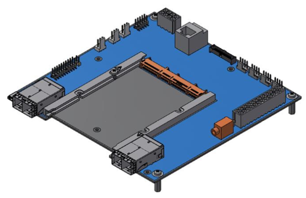
Install the OCP 3.0 adapter card in the multi-host board.
Prior to installing the OCP 3.0 adapter card in the multi-host board, unscrew the screw as shown in the below figure.

Applying even pressure at both corners of the card, insert the OCP 3.0 card into the multi-host board using the guiding rails until a click sound is heard.

Secure the OCP card with the screw you removed in the previous step.

When the OCP 3.0 adapter is properly seated, the card's golden fingers are connected to the multi-host OCP 3.0 connector.

Connect the external main power connector with the 12V power source.
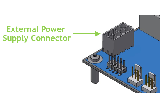
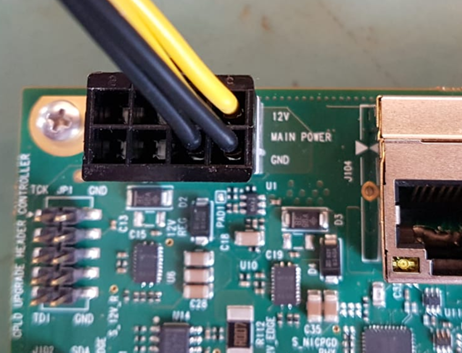
TBD: What kind of power cable? need pin description.
Should we add anything regarding LED operations?
Install the MiniSAS auxiliary cards in a server and connect them to the multi-host board.
Applying even pressure at both corners of the card, insert the MiniSAS auxiliary cards to a server.

When the MiniSAS auxiliary cards are properly seated, the harness connector is aligned with the slot opening, and the MiniSAS auxiliary faceplate is visible against the system chassis.
Connect the MiniSAS auxiliary cards with the OCP multi-host board using the supplied MiniSAS cables.
instructions.
To uninstall the adapter card, see Uninstalling the Card.
Cables and Modules
Cable Installation
All cables can be inserted or removed with the unit powered on.
To insert a cable, press the connector into the port receptacle until the connector is firmly seated.
Support the weight of the cable before connecting the cable to the adapter card. Do this by using a cable holder or tying the cable to the rack.
Determine the correct orientation of the connector to the card before inserting the connector. Do not try and insert the connector upside down. This may damage the adapter card.
Insert the connector into the adapter card. Be careful to insert the connector straight into the cage. Do not apply any torque, up or down, to the connector cage in the adapter card.
Make sure that the connector locks in place.
WarningWhen installing cables make sure that the latches engage.
ImportantAlways install and remove cables by pushing or pulling the cable and connector in a straight line with the card.
After inserting a cable into a port, the Green LED indicator will light when the physical connection is established (that is, when the unit is powered on and a cable is plugged into the port with the other end of the connector plugged into a functioning port). See Adapter Card LED Operations.
After plugging in a cable, lock the connector using the latching mechanism particular to the cable vendor. When data is being transferred the Green LED will blink. See Adapter Card LED Operations under the Interfaces section.
Care should be taken as not to impede the air exhaust flow through the ventilation holes. Use cable lengths that allow for routing horizontally around to the side of the chassis before bending upward or downward in the rack.
To remove a cable, disengage the locks and slowly pull the connector away from the port receptacle. The LED indicator will turn off when the cable is unseated.
Kit Power Sequence
instructions.
Install the OCP 3.0 card to the multi-host board and power up.
Install the MiniSAS auxiliary cards and connect them to the multi-host board using the supplied harnesses.
Power up the server.
Powering up the auxiliary cards while the OCP 3.0 card is not powered up may cause serious damage to the cards.
Once powered up, the OCP 3.0 board FRU EEPROM address in multi-host mode is changed to 0x56.
In power down, power down the MiniSAS auxiliary cards and then the OCP 3.0 card.