VXLAN
Data centers are being increasingly consolidated and outsourced in an effort to improve the deployment time of applications and reduce operational costs, and applications are constantly raising demand for compute, storage, and network resource. Thus, in order to scale compute, storage, and network resources, physical resources are being abstracted from their logical representation, in what is referred to as server, storage, and network virtualization. Virtualization can be implemented in various layers of computer systems or networks.
Multi-tenant data centers are taking advantage of the benefits of server virtualization to provide a new kind of hosting—a virtual hosted data center. Multi-tenant data centers are ones where individual tenants could belong to a different company or a different department. To a tenant, virtual data centers are similar to their physical counterparts, consisting of end-stations attached to a network, complete with services such as load balancers and firewalls. To tenant systems, a virtual network looks like a normal network, except that the only end-stations connected to the virtual network are those belonging to a tenant’s specific virtual network.
How a virtual network is implemented does not generally matter to the tenant; what matters is that the service provided (Layer 2 (L2) or Layer 3 (L3)) has the right semantics, performance, etc. It could be implemented via a pure routed network, a pure bridged network, or a combination of bridged and routed networks.
VXLAN (Virtual eXtensible Local Area Network) addresses the above requirements of the L2 and L3 data center network infrastructure in the presence of virtual networks in a multi-tenant environment. It runs over the existing networking infrastructure and provides a means to “stretch” an L2 network. Each overlay bridge is called a VXLAN segment. Only machines within the same VXLAN segment can communicate with each other. Each VXLAN segment is identified through a 24-bit segment ID called “VXLAN Network Identifier (VNI)”. A network endpoint which performs a conversion from virtual to physical network and back is called VXLAN Tunnel End-Point or VTEP.
In virtual environments, it is typically required to use logical switches to forward traffic between different virtual machines (VMs) on the same physical host, between virtual machines and the physical machines and between networks. Virtual switch environments use an OVSDB management protocol for configuration and state discovery of the virtual networks. OVSDB protocol allows programmable access to the database of virtual switch configuration.
To enable VXLAN:
Configure jumbo frames for NVE ports. Run:
switch(config)#interfaceethernet1/1-1/4mtu9216forceConfigure jumbo frames for underlay-facing ports. Run:
switch(config)#interfaceethernet1/17mtu9216forceCreate VLAN for all VXLAN traffic. Run:
switch(config)# vlan3Configure Overlay interfaces with VXLAN VLAN. Run:
switch(config)#interfaceethernet1/17switchport access vlan3Enable IP routing. Run:
switch(config)# ip routing vrfdefaultConfigure interface on the VXLAN VLAN and configure an IP address for it. Run:
switch(config)#interfacevlan3switch(configinterfacevlan3)# ip address33.33.33.254255.255.255.0switch(configinterfacevlan3)#interfacevlan3mtu9216Enable NVE protocol. Run:
switch(config)# protocol nveConfigure interface NVE. Run:
switch(config)#interfacenve1Create loopback interface to terminate the VXLAN tunnel. The IP address of the interface will be a VTEP endpoint address, and needs to be reachable in the underlay network. Run:
switch(config)#interfaceloopback1switch(configinterfaceloopback1)# ip address1.2.3.4255.255.255.255switch(config)#interfacenve1vxlan sourceinterfaceloopback1Configure routing to other VTEP devices. Run:
switch(config)# ip route vrfdefault1.2.3.5/3233.33.33.253switch(config)# ip route vrfdefault1.2.3.6/3233.33.33.252Configure overlay-facing ports for NVE mode. Run:
switch(config)#interfaceethernet1/1nve mode only forceswitch(config)#interfaceethernet1/2nve mode only forceswitch(config)#interfaceethernet1/3nve mode only forceswitch(config)#interfaceethernet1/4nve mode only force
For deployments with a controller, set up OVSDB:
Start OVSDB server. Run:
switch(config)# ovs ovsdb serverConfigure the OVSDB manager to an IP address of a controller. Run:
switch(config)# ovs ovsdb manager remote ssl ip address10.130.250.5
For controller-less deployments, configure the bridging from the CLI directly:
Create bridges. Run:
switch(config)#interfacenve1nve bridge7777switch(config)#interfaceethernet1/1nve vlan10bridge7777Configure source-node replication. Run:
switch(config)# nointerfacenve1nve fdb flood load-balanceConfigure flood addresses for BUM traffic. Run:
switch(config)#interfacenve1nve fdb flood bridge7777address1.2.3.5switch(config)#interfacenve1nve fdb flood bridge7777address1.2.3.6Configure FDB remote learning. Run:
switch(config)#interfacenve1nve fdb learning remote

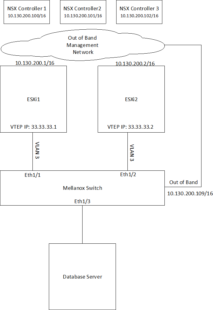
Hardware Topology
2 ESXi servers pre-configured with VXLAN networking using VMware NSX
3 NSX Controllers available for VXLAN unicast type logical switches
1 NVIDIA switch connected to the ESXi servers and to a physical database server
Out-of-band network for management and a VLAN network to carry VXLAN traffic
Switch Configuration
Configure jumbo frames on ESXi and Database server facing interfaces. Run:
switch(config)#interfaceethernet1/1-1/3mtu9216forceCreate VLAN 3 to carry VXLAN traffic (if it does not exist yet). Run:
switch(config)# vlan3switch(config vlan3)# exitswitch(config)#Enable IP routing. Run:
switch(config)# ip routing vrfdefaultCreate an interface on VLAN 3 and assign an IP address to it.
The IP address must be the default gateway of the VXLAN netstack created by NSX after enabling VXLAN traffic on the hosts.
To check the default gateway in vSphere web client select an ESXi host and go to: Configure -> TCP/IP configuration.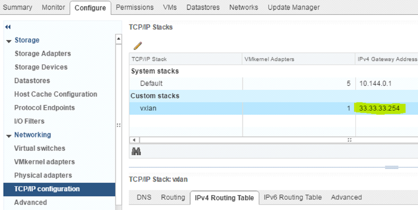
switch(config)#interfacevlan3switch(configinterfacevlan3)# ip address33.33.33.254255.255.255.0switch(configinterfacevlan3)#interfacevlan3mtu9216Create a loopback interface to communicate with VTEPs on the ESXi servers by routing through “interface vlan 3”. This interface will be the VTEP IP assigned to the switch. Run:
switch(config)#interfaceloopback1switch(configinterfaceloopback1)# ip address1.2.3.4255.255.255.255Enable NVE protocol. Run:
switch(config)# protocol nveConfigure interface NVE. Run:
switch(config)#interfacenve1Configure the source of the NVE interface to be the loopback created above. Run:
switch(config)#interfacenve1vxlan sourceinterfaceloopback1Start the OVSDB server and connect it to the NSX Controllers. Run:
switch(config)# ovs ovsdb serverswitch(config)# ovs ovsdb manager remote ssl ip address10.130.200.100switch(config)# ovs ovsdb manager remote ssl ip address10.144.200.101switch(config)# ovs ovsdb manager remote ssl ip address10.144.200.102Configure the port facing the Database server as an NVE port. Run:
switch(config)#interfaceethernet1/3nve mode only forceGet the switch certificate for later configuration in the NSX Manager. Run:
switch(config)# show crypto certificate name system-self-signedpublic-pemCopy the certificate starting with the line:
-----BEGIN CERTIFICATE-----
Until the line:
-----END CERTIFICATE-----
Make sure to include both of those lines.
ImportantNSX Manager Configuration
ImportantAdding Hosts to Replication Cluster
In NSX Manager, go to “Service Definitions” → “Hardware Devices”.
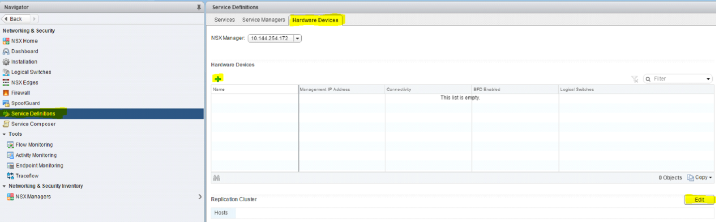
Under “Replication Cluster” click Edit.
Add both of the ESXi servers to the replication cluster.
All hosts added to the replication cluster can replicate BUM (Broadcast, Unknown unicast and Multicast) traffic to other ESXi servers.
When the switch needs to send BUM traffic to a virtual machine, it will select one of the hosts in the replication cluster and send the traffic to it, the host will then replicate it to all other ESXi hosts.
It is recommended to add at least 2 ESXi servers to the replication cluster for redundancy.
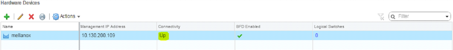
Adding the Switch to NSX
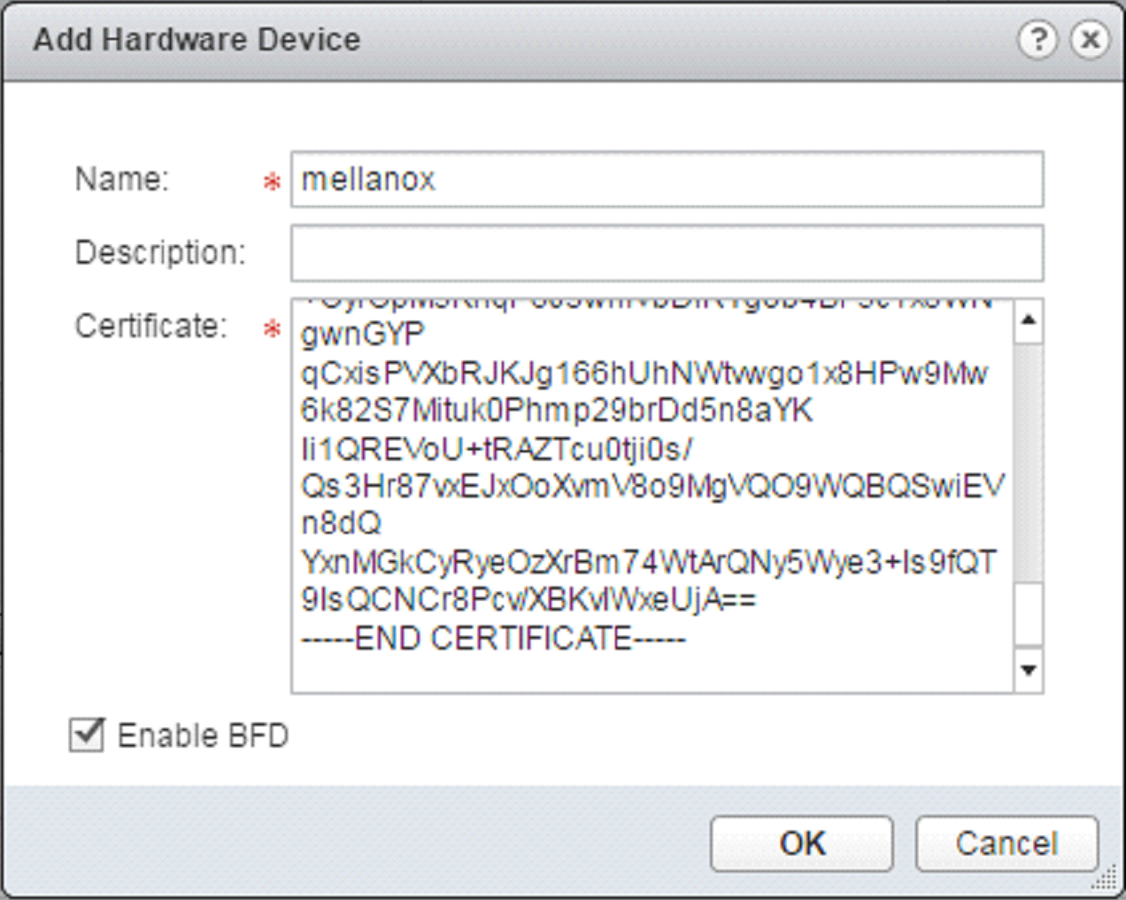
Under Hardware Devices click the + sign to add a new hardware device.
Fill in a name for the new hardware device.
Fill in the switch certificate we got earlier.
Click OK.
Wait until the new switch is showing as “UP” under the connectivity column, you may need to refresh vSphere client a few times.
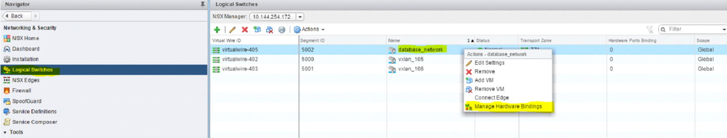
Mapping a Logical Switch to a Physical Switch Port
In NSX Manager go to “Logical Switches”.
Right click the logical switch you wish to map to the physical switch port and select “Manage Hardware Bindings”.
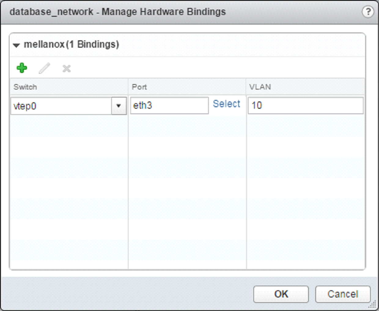
Click the “+” sign to add a new mapping instance.
Click Select under the port column and select port “eth3”, this corresponds to “ 1/3” we configured earlier as an NVE port in the switch.
Under the VLAN column, set the VLAN that will map this logical switch to this specific switch port, you can have multiple logical switches mapped to the same port on a different VLAN (for example to connect a firewall appliance to logical switches). For “access” configuration (no VLAN is required on the host connected to the physical switch port) use VLAN 1.
Click OK.
For more information about this feature and its potential applications, please refer to the following community posts:
RoCEv2 Using PFC and ECN
The following figure and flow demonstrate how to configure RoCEv2 using PFC and ECN. RoCEv2 QoS is preserved by DSCP.
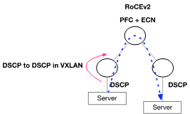
DSCP is automatically driven from the original packet into the VXLAN header in Onyx.
Configure the switch buffer to support lossless traffic.
traffic pool roce type lossless traffic pool roce memory percent
50.00traffic pool roce mapswitch-priority3
Enable ECN.
interfaceethernet1/15traffic-class3congestion-control ecn minimum-absolute150maximum-absolute1500interfaceethernet1/16traffic-class3congestion-control ecn minimum-absolute150maximum-absolute1500interfacemlag-port-channel7-8traffic-class3congestion-control ecn minimum-absolute150maximum-absolute1500interfaceport-channel1traffic-class3congestion-control ecn minimum-absolute150maximum-absolute1500interfaceethernet1/15traffic-class6dcb ets strictinterfaceethernet1/16traffic-class6dcb ets strictinterfacemlag-port-channel7-8traffic-class6dcb ets strictinterfaceport-channel1traffic-class6dcb ets strict
Set QoS trust to DSCP.
interfaceethernet1/15-1/16qos trust L3interfacemlag-port-channel7-8qos trust L3interfaceport-channel1qos trust L3
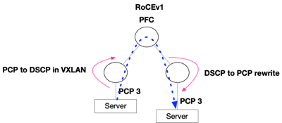
RoCEv1 Using PFC
The following figure and flow demonstrate how to configure RoCEv1 using PFC. RoCEv1 QoS is based on the PCP field sent by the server.
Configure the switch buffer to support lossless traffic.
traffic pool roce type lossless traffic pool roce memory percent
50.00traffic pool roce mapswitch-priority3
Set Uplinks and IPL trust to DSCP.
interfaceethernet1/15-1/16qos trust L3interfaceport-channel1qos trust L3
Set Downlinks trust to PCP.
interfacemlag-port-channel7-8qos trust L2
Set Downlinks rewrite to DSCP. This will allow translation from PCP to DSCP in VXLAN.
interfacemlag-port-channel7-8qos rewrite dscp
Set Uplinks and IPL rewrite to PCP. This will allow translation from DSCP to PCP.
interfaceethernet1/15-1/16qos rewrite pcpinterfaceport-channel1qos rewrite pcp