Host Configuration
All worker nodes must have the same PCIe placement for the BlueField-3 NIC and must display the same interface name.
The hypervisor used in this Reference Deployment Guide (RDG) is based on Ubuntu 24.04 with KVM.
While this document does not detail the KVM installation process, it is important to note that the setup requires the following ISOs to deploy the Firewall, Jump, and MaaS virtual machines (VMs):
Ubuntu 24.04
pfSense-CE-2.7.2
To implement the solution, three Linux bridges must be created on the hypervisor:
Ensure a DHCP record is configured for the lab-br bridge interface in your trusted LAN to assign it an IP address.
lab-br– connects the Firewall VM to the trusted LAN.mgmt-br– Connects the various VMs to the host management network.hs-br – Connects the Firewall VM to the high-speed network.
Additionally, an MTU of 9000 must be configured on the management and high-speed bridges ( mgmt-br and hs-br ) as well as their uplink interfaces to ensure optimal performance.
Hypervisor netplan configuration
            network:
    ethernets:
        eno1:
            dhcp4: false
        eno2:
            dhcp4: false
            mtu: 9000
        ens2f0np0:
            dhcp4: false
            mtu: 9000
    bridges:
      lab-br:
         interfaces: [eno1]
         dhcp4: true
      mgmt-br:
         interfaces: [eno2]
         dhcp4: false
         mtu: 9000
      hs-br:
         interfaces: [ens2f0np0]
         dhcp4: false
         mtu: 9000
    version: 2
Apply the configuration:
Hypervisor Console
$ sudo netplan apply
Firewall VM - pfSense Installation and Interface Configuration
Download the pfSense CE (Community Edition) ISO to your hypervisor and proceed with the software installation.
Suggested spec:
- vCPU: 2
- RAM: 2GB
- Storage: 10GB
Network interfaces
- Bridge device connected to lab-br
- Bridge device connected to mgmt-br
- Bridge device connected to hs-br
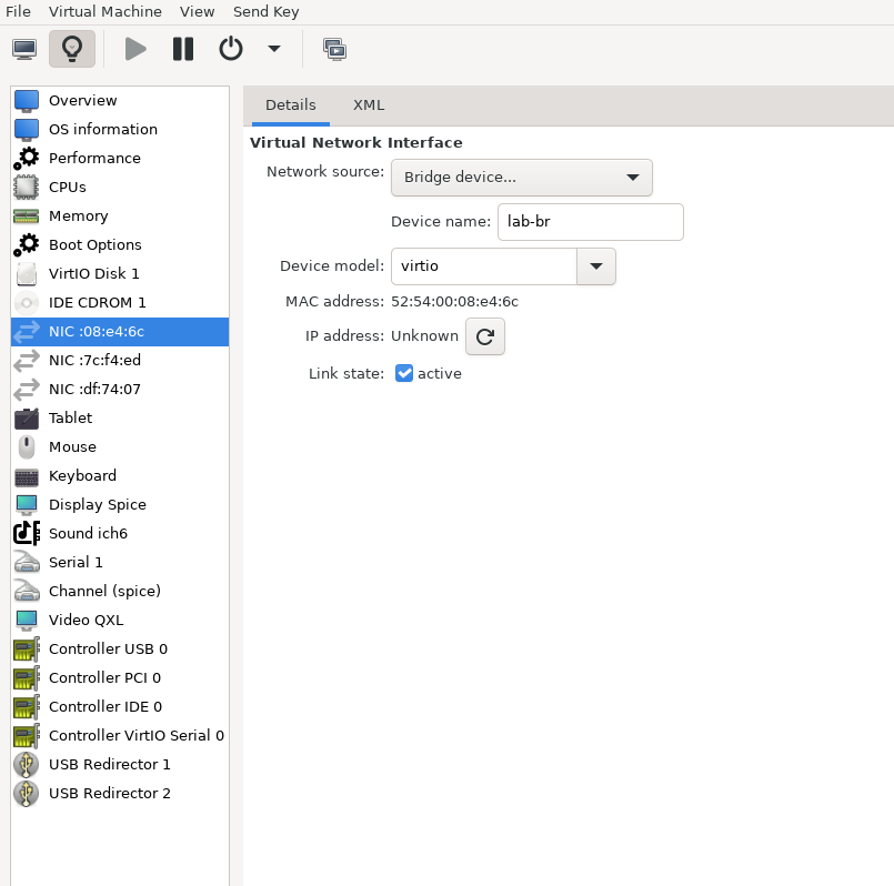
The Firewall VM must be connected to all three Linux bridges on the hypervisor. Before beginning the installation, ensure that three virtual network interfaces of type "Bridge device" are configured. Each interface should be connected to a different bridge (lab-br, mgmt-br, and hs-br) as illustrated in the diagram below.
After completing the installation, the setup wizard displays a menu with several options, such as "Assign Interfaces" and "Reboot System." During this phase, you must configure the network interfaces for the Firewall VM.
Select Option 2: "Set interface(s) IP address" and configure the interfaces as follows:
- WAN (lab-br) – Trusted LAN IP (Static/DHCP)
- LAN (mgmt-br) – Static IP 10.0.110.254/24
- OPT1 (hs-br) – Static IP 10.0.123.254/22
- Once the interface configuration is complete, use a web browser within the host management network to access the Firewall web interface and finalize the configuration.
Next, proceed with installing the Jump VM. This VM serves as a platform for running a browser for accessing the firewall’s web interface (UI) for post-installation configuration.
Jump VM
Suggested specifications:
- vCPU: 4
- RAM: 8GB
- Storage: 25GB
- Network interface: Bridge device, connected to
mgmt-br
Procedure:
Install standard Ubuntu 24.04 on each host . Use the following login credentials across all nodes in this deployment:
Username
Password
depuser
user
Enable internet connectivity and DNS resolution by creating the following Netplan configuration:
NoteUse
10.0.110.254as a temporary DNS nameserver until the MaaS VM is installed and configured. After completing the MaaS installation, update the Netplan file to replace this address with the MaaS IP:10.0.110.252.Jump Node netplan
network: ethernets: enp1s0: dhcp4:
falseaddresses: [10.0.110.253/24] nameservers: search: [dpf.rdg.local.domain] addresses: [10.0.110.254] routes: - to:defaultvia:10.0.110.254version:2Apply the configuration:
Jump Node Console
depuser@jump:~$ sudo netplan apply
Update and upgrade the system:
Jump Node Console
            depuser@jump:~$ sudo apt update -y
depuser@jump:~$ sudo apt upgrade -y
Install and configure the Xfce desktop environment and XRDP (complementary packages for RDP):
Jump Node Console
            depuser@jump:~$ sudo apt install -y xfce4 xfce4-goodies
depuser@jump:~$ sudo apt install -y lightdm-gtk-greeter
depuser@jump:~$ sudo apt install -y xrdp
depuser@jump:~$ echo "xfce4-session" | tee .xsession
depuser@jump:~$ sudo systemctl restart xrdp
Install Firefox for accessing the Firewall web interface:
Jump Node Console
$ sudo apt install -y firefox
Install and configure an NFS server with the
/mnt/dpf_sharedirectory:Jump Node Console
            $ sudo apt install -y nfs-server
$ sudo mkdir -m 777 /mnt/dpf_share
$ sudo vi /etc/exports
Add the following line to
/etc/exports:Jump Node Console
/mnt/dpf_share 10.0.110.0/24(rw,sync,no_subtree_check)
Restart the NFS server:
Jump Node Console
$ sudo systemctl restart nfs-server
Create the directory
bfbunder/mnt/dpf_sharewith the same permissions as the parent directory:Jump Node Console
$ sudo mkdir -m 777 /mnt/dpf_share/bfb
Generate an SSH key pair for
depuserin the jump node. These keys will later be imported to the admin user in MaaS to enable password-less login to the provisioned servers):Jump Node Console
depuser@jump:~$ ssh-keygen -t rsa
Firewall VM – Web Configuration
From your Jump node, open a Firefox web browser and navigate to the pfSense web UI (http://10.0.110.254. The default login credentials are admin/pfsense). The login page should appear as follows:
The IP addresses from the trusted LAN network under "DNS servers" and "Interfaces - WAN" are blurred.

Configure the following settings:
The following screenshots display only a part of the configuration view. Make sure to not miss any of the steps mentioned below!
Interfaces
- WAN—Mark “Enable interface”, unmark “Block private networks and loopback addresses”, “MTU”: 9000

- LAN—Mark “Enable interface”, “IPv4 configuration type”: “MTU”: 9000, Static IPv4 ("IPv4 Address": 10.0.110.254/24, "IPv4 Upstream Gateway": None)

- OPT1—Mark “Enable interface”, “IPv4 configuration type”: “MTU”: 9000, Static IPv4 ("IPv4 Address": 10.0.123.254/22, "IPv4 Upstream Gateway": None)

Firewall:
NAT -> Port Forward -> Add rule -> “Interface”: WAN, “Address Family”: IPv4, “Protocol”: TCP, “Destination”: WAN address, “Destination port range”: (“From port”: SSH, “To port”: SSH), “Redirect target IP”: (“Type”: Address or Alias, “Address”: 10.0.110.253), “Redirect target port”: SSH, “Description”: NAT SSH

NAT -> Port Forward -> Add rule -> “Interface”: WAN, “Address Family”: IPv4, “Protocol”: TCP, “Destination”: WAN address, “Destination port range”: (“From port”: MS RDP, “To port”: MS RDP), “Redirect target IP”: (“Type”: Address or Alias, “Address”: 10.0.110.253), “


Rules -> OPT1 -> Add rule -> “Action”: Pass , “Interface”: OPT1 , “Address Family”: IPv4+IPv6 , “Protocol”: Any , “Source”: Any , “Destination”: Any

MaaS VM
Suggested specifications:
- vCPU: 4
- RAM: 4 GB
- Storage: 100 GB
- Network interface: Bridge device, connected to
mgmt-br
Procedure:
- Perform a regular Ubuntu installation on the MaaS VM.
Create the following Netplan configuration to enable internet connectivity and DNS resolution:
NoteUse
10.0.110.254as a temporary DNS nameserver. After the MaaS installation, replace this with the MaaS IP address (10.0.110.252) in both the Jump and MaaS VM Netplan files.MaaS netplan
network: ethernets: enp1s0: dhcp4:
falseaddresses: [10.0.110.252/24] nameservers: search: [dpf.rdg.local.domain] addresses: [10.0.110.254] routes: - to:defaultvia:10.0.110.254version:2Apply the netplan configuration:
MaaS Console
depuser@maas:~$ sudo netplan apply
Update and upgrade the system:
MaaS Console
            depuser@maas:~$ sudo apt update -y
depuser@maas:~$ sudo apt upgrade -y
Install PostgreSQL and configure the database for MaaS:
MaaS Console
            $ sudo -i
# apt install -y postgresql
# systemctl disable --now systemd-timesyncd
# export MAAS_DBUSER=maasuser
# export MAAS_DBPASS=maaspass
# export MAAS_DBNAME=maas
# sudo -i -u postgres psql -c "CREATE USER \"$MAAS_DBUSER\" WITH ENCRYPTED PASSWORD '$MAAS_DBPASS'"
# sudo -i -u postgres createdb -O "$MAAS_DBUSER" "$MAAS_DBNAME"
Install MaaS:
MaaS Console
# snap install maas
Initialize MaaS:
MaaS Console
# maas init region+rack --maas-url http://10.0.110.252:5240/MAAS --database-uri "postgres://$MAAS_DBUSER:$MAAS_DBPASS@localhost/$MAAS_DBNAME"
Create an admin account:
MaaS Console
# maas createadmin --username admin --password admin --email admin@example.com
Save the admin API key:
MaaS Console
# maas apikey --username admin > admin-apikey
Log in to the MaaS server:
MaaS Console
# maas login admin http://localhost:5240/MAAS "$(cat admin-apikey)"
Configure MaaS (Substitute <Trusted_LAN_NTP_IP> and <Trusted_LAN_DNS_IP> with the IP addresses in your environment):
MaaS Console
            # maas admin domain update maas name="dpf.rdg.local.domain"
# maas admin maas set-config name=ntp_servers value="<Trusted_LAN_NTP_IP>"
# maas admin maas set-config name=network_discovery value="disabled"
# maas admin maas set-config name=upstream_dns value="<Trusted_LAN_DNS_IP>"
# maas admin maas set-config name=dnssec_validation value="no"
# maas admin maas set-config name=default_osystem value="ubuntu"
Define and configure IP ranges and subnets:
MaaS Console
            # maas admin ipranges create type=dynamic start_ip="10.0.110.51" end_ip="10.0.110.120"
# maas admin ipranges create type=dynamic start_ip="10.0.110.201" end_ip="10.0.110.240"
# maas admin ipranges create type=reserved start_ip="10.0.110.10" end_ip="10.0.110.10" comment="c-plane VIP"
# maas admin ipranges create type=reserved start_ip="10.0.110.200" end_ip="10.0.110.200" comment="kamaji VIP"
# maas admin ipranges create type=reserved start_ip="10.0.110.251" end_ip="10.0.110.254" comment="dpfmgmt"
# maas admin vlan update 0 untagged dhcp_on=True primary_rack=maas mtu=9000
# maas admin dnsresources create fqdn=kube-vip.dpf.rdg.local.domain ip_addresses=10.0.110.10
# maas admin dnsresources create fqdn=jump.dpf.rdg.local.domain ip_addresses=10.0.110.253
# maas admin dnsresources create fqdn=fw.dpf.rdg.local.domain ip_addresses=10.0.110.254
# maas admin fabrics create
Success.
Machine-readable output follows:
{
"class_type": null,
"name": "fabric-1",
"id": 1,
...
# maas admin subnets create name="fake-dpf" cidr="20.20.20.0/24" fabric=1
Complete MaaS setup:
- Connect to the Jump node GUI and access the MaaS UI at
http://10.0.110.252:5240/MAAS. - On the first page, verify the "Region Name" and "DNS Forwarder," then continue.
On the image selection page, select Ubuntu 24.04 LTS (amd64) and sync the image.

Import the previously generated SSH key (
id_rsa.pub) for thedepuserinto the MaaS admin user profile and finalize the setup.
- Connect to the Jump node GUI and access the MaaS UI at
Configure DHCP snippets:
- Navigate to Settings → DHCP Snippets → Add Snippet.
Fill in the following fields:
- Name:
dpu-bmc-oob-mgmt - Toggle on "Enabled"
- Type: IP Range
- Applies to:
10.0.110.201-10.0.110.240
- Name:
Fill in the content of the DHCP snippet field with the following (replace the MAC address with the appropriate value for your DPU workers' BMC and OOB interface MAC) addresses:
DHCP snippet
            # dpuworker1
host dpuworker1-bmc {
   #
   # Node DHCP snippets
   #

   hardware ethernet 58:a2:e1:73:6a:0b;
   fixed-address 10.0.110.201;
}
host dpuworker1-oob{
   #
   # Node DHCP snippets
   #

   hardware ethernet 58:a2:e1:73:6a:0a;
   fixed-address 10.0.110.221;
}
# dpuworker2
host dpuworker2-bmc {
   #
   # Node DHCP snippets
   #

   hardware ethernet 58:a2:e1:73:6a:7d;
   fixed-address 10.0.110.202;
}
host dpuworker2-oob{
   #
   # Node DHCP snippets
   #

   hardware ethernet 58:a2:e1:73:6a:7c;
   fixed-address 10.0.110.222;
}
# dpuworker3
host dpuworker3-bmc {
   #
   # Node DHCP snippets
   #

   hardware ethernet 58:a2:e1:73:72:a7;
   fixed-address 10.0.110.203;
}
host dpuworker3-oob{
   #
   # Node DHCP snippets
   #

   hardware ethernet 58:a2:e1:73:72:a6;
   fixed-address 10.0.110.213;
}
# dpuworker4
host dpuworker4-bmc {
   #
   # Node DHCP snippets
   #

   hardware ethernet 58:a2:e1:73:6c:dd;
   fixed-address 10.0.110.204;
}
host dpuworker4-oob{
   #
   # Node DHCP snippets
   #

   hardware ethernet 58:a2:e1:73:6c:dc;
   fixed-address 10.0.110.214;
}
Go to Settings → Deploy, set "Default OS release" to Ubuntu 24.04 LTS Noble Numbat, and save.

- Update the DNS nameserver IP address in the Netplan files for both the Jump and MaaS VMs from
10.0.110.254to10.0.110.252, then reapply the configuration.
K8s Master VMs
Suggested specifications:
- vCPU: 8
- RAM: 16GB
- Storage: 100GB
- Network interface: Bridge device, connected to
mgmt-br
Before provisioning the Kubernetes (K8s) Master VMs with MaaS, create the required virtual disks with empty storage. Use the following one-liner to create three 100 GB QCOW2 virtual disks:
Hypervisor Console
$ for i in $(seq 1 3); do qemu-img create -f qcow2 /var/lib/libvirt/images/master$i.qcow2 100G; done
This command generates the following disks in the
/var/lib/libvirt/images/directory:master1.qcow2master2.qcow2master3.qcow2
Configure VMs in virt-manager:
Open virt-manager and create three virtual machines:
- Assign the corresponding virtual disk (
master1.qcow2,master2.qcow2, ormaster3.qcow2) to each VM. - Configure each VM with the suggested specifications (vCPU, RAM, storage, and network interface).
- Assign the corresponding virtual disk (
- During the VM setup, ensure the NIC is selected under the Boot Options tab. This ensures the VMs can PXE boot for MaaS provisioning.
- Once the configuration is complete, shut down all the VMs.
- After the VMs are created and configured, proceed to provision them via the MaaS interface. MaaS will handle the OS installation and further setup as part of the deployment process.
Install virsh and Set Up SSH Access
SSH to the MaaS VM from the Jump node:
MaaS Console
            depuser@jump:~$ ssh maas
depuser@maas:~$ sudo -i
Install the
virshclient to communicate with the hypervisor:MaaS Console
# apt install -y libvirt-clients
Generate an SSH key for the
rootuser and copy it to the hypervisor user in thelibvirtdgroup:MaaS Console
            # ssh-keygen -t rsa
# ssh-copy-id ubuntu@<hypervisor_MGMT_IP>
Verify SSH access and
virshcommunication with the hypervisor:MaaS Console
# virsh -c qemu+ssh://ubuntu@<hypervisor_MGMT_IP>/system list --all
Expected output:
MaaS Console
             Id   Name          State
------------------------------
 1    fw     running
 2    jump   running
 3    maas   running
 -    master1       shut off
 -    master2       shut off
 -    master3       shut off
Copy the SSH key to the required MaaS directory (for snap-based installations):
MaaS Console
            # mkdir -p /var/snap/maas/current/root/.ssh
# cp .ssh/id_rsa* /var/snap/maas/current/root/.ssh/
Get MAC Addresses of the Master VMs
Retrieve the MAC addresses of the Master VMs:
MaaS Console
# for i in $(seq 1 3); do virsh -c qemu+ssh://ubuntu@<hypervisor_MGMT_IP>/system dumpxml master$i | grep 'mac address'; done
Example output:
MaaS Console
            <mac address='52:54:00:a9:9c:ef'/>
<mac address='52:54:00:19:6b:4d'/>
<mac address='52:54:00:68:39:7f'/>
Add Master VMs to MaaS
Add the Master VMs to MaaS:
InfoOnce added, MaaS will automatically start the newly added VMs commissioning (discovery and introspection).
MaaS Console
            # maas admin machines create hostname=master1 architecture=amd64/generic mac_addresses='52:54:00:a9:9c:ef' power_type=virsh power_parameters_power_address=qemu+ssh://ubuntu@<hypervisor_MGMT_IP>/system power_parameters_power_id=master1 skip_bmc_config=1 testing_scripts=none
Success.
Machine-readable output follows:
{
    "description": "",
    "status_name": "Commissioning",
...
    "status": 1,
...
    "system_id": "c3seyq",
...
    "fqdn": "master1.dpf.rdg.local.domain",
    "power_type": "virsh",
...
    "status_message": "Commissioning",
    "resource_uri": "/MAAS/api/2.0/machines/c3seyq/"
}

# maas admin machines create hostname=master2 architecture=amd64/generic mac_addresses='52:54:00:19:6b:4d' power_type=virsh power_parameters_power_address=qemu+ssh://ubuntu@<hypervisor_MGMT_IP>/system power_parameters_power_id=master2 skip_bmc_config=1 testing_scripts=none

# maas admin machines create hostname=master3 architecture=amd64/generic mac_addresses='52:54:00:68:39:7f' power_type=virsh power_parameters_power_address=qemu+ssh://ubuntu@<hypervisor_MGMT_IP>/system power_parameters_power_id=master3 skip_bmc_config=1 testing_scripts=none
Repeat the command for
master2andmaster3with their respective MAC addresses.Verify commissioning by waiting for the status to change to "Ready" in MaaS.

After commissioning, the next phase is deployment (OS provisioning).
Configure Master VMs Network
To ensure persistence across reboots, assign a static IP address to the management interface of the master nodes.
For each Master VM:
Navigate to Network and click "actions" near the management interface (a small arrowhead pointing down), then select "Edit Physical".
Configure as follows:
Subnet: 10.0.110.0/24
IP Mode: Static Assign
Address: Assign
10.0.110.1formaster1,10.0.110.2formaster2, and10.0.110.3formaster3.
Save the interface settings for each VM.
Deploy Master VMs Using Cloud-Init
Use the following cloud-init script to configure the necessary software and ensure persistency:
Master nodes cloud-init
#cloud-config system_info: default_user: name: depuser passwd:
"$6$jOKPZPHD9XbG72lJ$evCabLvy1GEZ5OR1Rrece3NhWpZ2CnS0E3fu5P1VcZgcRO37e4es9gmriyh14b8Jx8gmGwHAJxs3ZEjB0s0kn/"lock_passwd:falsegroups: [adm, audio, cdrom, dialout, dip, floppy, lxd, netdev, plugdev, sudo, video] sudo: ["ALL=(ALL) NOPASSWD:ALL"] shell: /bin/bash ssh_pwauth: True package_upgrade:trueruncmd: - apt-get update - apt-get -y install nfs-commonDeploy the master VMs:
Select all three Master VMs → Actions → Deploy.
Toggle Cloud-init user-data and paste the cloud-init script.
Start the deployment and wait for the status to change to "Ubuntu 24.04 LTS".


Verify Deployment
SSH into the Master VMs from the Jump node:
Jump Node Console
            depuser@jump:~$ ssh master1
depuser@master1:~$
Run
sudowithout a password:Master1 Console
            depuser@master1:~$ sudo -i
root@master1:~#
Verify installed packages:
Master1 Console
            root@master1:~# apt list --installed | egrep 'nfs-common'
nfs-common/noble,now 1:2.6.4-3ubuntu5 amd64 [installed]
Reboot the Master VMs to complete the provisioning.
Master1 Console
root@master1:~# reboot
Repeat the verification commands for master2 andmaster3.