RDG for DPF with OVN-Kubernetes and HBN Services
Created on September 09, 2025
Scope
This Reference Deployment Guide (RDG) provides detailed instructions for deploying a Kubernetes (K8s) cluster using the DOCA Platform Framework (DPF). The guide covers setting up accelerated OVN-Kubernetes, Host-Based Networking (HBN) services, and additional services on NVIDIA® BlueField®-3 DPUs.
As a reference implementation, this guide focuses on using open-source components and outlines the entire deployment process, including bare metal and virtual machine provisioning with KVM virtualization and MaaS. It also addresses performance tuning to achieve optimal results.
Leveraging NVIDIA's DPF, administrators can provision and manage DPU resources within a Kubernetes cluster while deploying and orchestrating HBN and accelerated OVN-Kubernetes services. This approach enables full utilization of NVIDIA DPU hardware acceleration and offloading capabilities, maximizing data center workload efficiency and performance.
This guide is designed for experienced system administrators, system engineers, and solution architects who seek to deploy high-performance Kubernetes clusters and enable NVIDIA BlueField DPUs.
This reference implementation, as the name implies, is a specific, opinionated deployment example designed to address the use case described above.
While other approaches may exist to implement similar solutions, this document provides a detailed guide for this particular method.
Abbreviations and Acronyms
Term | Definition | Term | Definition |
BFB | BlueField Bootstream | K8S | Kubernetes |
BGP | Border Gateway Protocol | MAAS | Metal as a Service |
CNI | Container Network Interface | OVN | Open Virtual Network |
CSI | Container Storage Interface | RDG | Reference Deployment Guide |
DOCA | Data Center Infrastructure-on-a-Chip Architecture | RDMA | Remote Direct Memory Access |
DPF | DOCA Platform Framework | SFC | Service Function Chaining |
DPU | Data Processing Unit | SR-IOV | Single Root Input/Output Virtualization |
DTS | DOCA Telemetry Service | TOR | Top of Rack |
GENEVE | Generic Network Virtualization Encapsulation | VLAN | Virtual LAN (Local Area Network) |
HBN | Host Based Networking | VRR | Virtual Router Redundancy |
IPAM | IP Address Management | VTEP | Virtual Tunnel End Point |
Introduction
The NVIDIA BlueField-3 data processing unit (DPU) is a 400 Gb/s infrastructure compute platform designed for line-rate processing of software-defined networking, storage, and cybersecurity. BlueField-3 combines powerful computing, high-speed networking, and extensive programmability to deliver hardware-accelerated, software-defined solutions for demanding workloads.
NVIDIA DOCA unlocks the full potential of the NVIDIA BlueField platform, enabling rapid development of applications and services that offload, accelerate, and isolate data center workloads.
Host-based Networking (HBN) is a DOCA service that allows network architects to design networks based on layer-3 (L3) protocols. HBN enables routing to run on the server side by using BlueField as a BGP router. The HBN solution encapsulates a set of network functions inside a container, which is deployed as a service pod on BlueField's Arm cores.
OVN-Kubernetes is a Kubernetes CNI network plugin that provides robust networking for Kubernetes clusters. Built on Open Virtual Network (OVN) and Open vSwitch (OVS), it supports hardware acceleration to offload OVS packet processing to NIC/DPU hardware. With OVS-DOCA, an extension of traditional OVS-DPDK and OVS-Kernel, accelerated OVN-Kubernetes delivers industry-leading performance, functionality, and efficiency. Running OVN-Kubernetes on the DPU reserves host CPUs exclusively for workloads, maximizing system resources.
Deploying and managing DPUs and their associated DOCA services—especially at scale—can be challenging. Without a provisioning and orchestration system, the complexity of managing the DPU lifecycle, deploying DOCA services, and providing the necessary network configuration on the DPU to redirect the network traffic via those services (service function chaining, or SFC) becomes a significant burden for cluster and system administrators; which is where the DOCA Platform Framework (DPF) comes into play.
DPF simplifies DPU management by providing orchestration through a Kubernetes API. It handles the provisioning and lifecycle management of DPUs, orchestrates specialized DPU services, and automates tasks such as service function chaining (SFC). This ensures seamless deployment of DOCA services like OVN-Kubernetes and HBN, allowing traffic to be efficiently offloaded and routed through HBN's data plane.
With DPF, users can efficiently manage and scale DPUs within their clusters while automating critical processes. DPF orchestrates the deployment of OVN-Kubernetes and HBN, optimizing performance with features such as offloaded OVN-Kubernetes CNI and accelerated traffic routing through HBN.
This RDG provides a comprehensive, practical example of installing the DPF system on a Kubernetes cluster. It also demonstrates performance optimizations, including Jumbo frame implementation, with results validated through standard RDMA and TCP workload tests.
References
- NVIDIA BlueField DPU
- NVIDIA DOCA
- NVIDIA DOCA HBN Service
- NVIDIA DOCA Telemetry Service
- NVIDIA DOCA BlueMan Service
- NVIDIA DPF Release Notes
- NVIDIA DPF GitHub Repository
- NVIDIA DPF System Overview
- NVIDIA DPF HBN and OVN-Kubernetes User Guide
- NVIDIA Ethernet Switching
- NVIDIA Cumulus Linux
- NVIDIA Network Operator
- What is K8s?
- Kubespray
- OVN-Kubernetes
Solution Architecture
Key Components and Technologies
NVIDIA BlueField® Data Processing Unit (DPU)
The NVIDIA® BlueField® data processing unit (DPU) ignites unprecedented innovation for modern data centers and supercomputing clusters. With its robust compute power and integrated software-defined hardware accelerators for networking, storage, and security, BlueField creates a secure and accelerated infrastructure for any workload in any environment, ushering in a new era of accelerated computing and AI.
NVIDIA DOCA Software Framework
NVIDIA DOCA™ unlocks the potential of the NVIDIA® BlueField® networking platform. By harnessing the power of BlueField DPUs and SuperNICs, DOCA enables the rapid creation of applications and services that offload, accelerate, and isolate data center workloads. It lets developers create software-defined, cloud-native, DPU- and SuperNIC-accelerated services with zero-trust protection, addressing the performance and security demands of modern data centers.
10/25/40/50/100/200 and 400G Ethernet Network Adapters
The industry-leading NVIDIA® ConnectX® family of smart network interface cards (SmartNICs) offer advanced hardware offloads and accelerations.
NVIDIA Ethernet adapters enable the highest ROI and lowest Total Cost of Ownership for hyperscale, public and private clouds, storage, machine learning, AI, big data, and telco platforms.
The NVIDIA® LinkX® product family of cables and transceivers provides the industry’s most complete line of 10, 25, 40, 50, 100, 200, and 400GbE in Ethernet and 100, 200 and 400Gb/s InfiniBand products for Cloud, HPC, hyperscale, Enterprise, telco, storage and artificial intelligence, data center applications.
NVIDIA Spectrum Ethernet Switches
Flexible form-factors with 16 to 128 physical ports, supporting 1GbE through 400GbE speeds.
Based on a ground-breaking silicon technology optimized for performance and scalability, NVIDIA Spectrum switches are ideal for building high-performance, cost-effective, and efficient Cloud Data Center Networks, Ethernet Storage Fabric, and Deep Learning Interconnects.
NVIDIA combines the benefits of NVIDIA Spectrum™ switches, based on an industry-leading application-specific integrated circuit (ASIC) technology, with a wide variety of modern network operating system choices, including NVIDIA Cumulus® Linux , SONiC and NVIDIA Onyx®.
NVIDIA® Cumulus® Linux is the industry's most innovative open network operating system that allows you to automate, customize, and scale your data center network like no other.
The NVIDIA Network Operator simplifies the provisioning and management of NVIDIA networking resources in a Kubernetes cluster. The operator automatically installs the required host networking software - bringing together all the needed components to provide high-speed network connectivity. These components include the NVIDIA networking driver, Kubernetes device plugin, CNI plugins, IP address management (IPAM) plugin and others. The NVIDIA Network Operator works in conjunction with the NVIDIA GPU Operator to deliver high-throughput, low-latency networking for scale-out, GPU computing clusters.
Kubernetes is an open-source container orchestration platform for deployment automation, scaling, and management of containerized applications.
Kubespray is a composition of Ansible playbooks, inventory, provisioning tools, and domain knowledge for generic OS/Kubernetes clusters configuration management tasks and provides:
- A highly available cluster
- Composable attributes
- Support for most popular Linux distributions
OVN-Kubernetes (Open Virtual Networking - Kubernetes) is an open-source project that provides a robust networking solution for Kubernetes clusters with OVN (Open Virtual Networking) and Open vSwitch (Open Virtual Switch) at its core. It is a Kubernetes networking conformant plugin written according to the CNI (Container Network Interface) specifications.
RDMA is a technology that allows computers in a network to exchange data without involving the processor, cache or operating system of either computer.
Like locally based DMA, RDMA improves throughput and performance and frees up compute resources.
Solution Design
Solution Logical Design
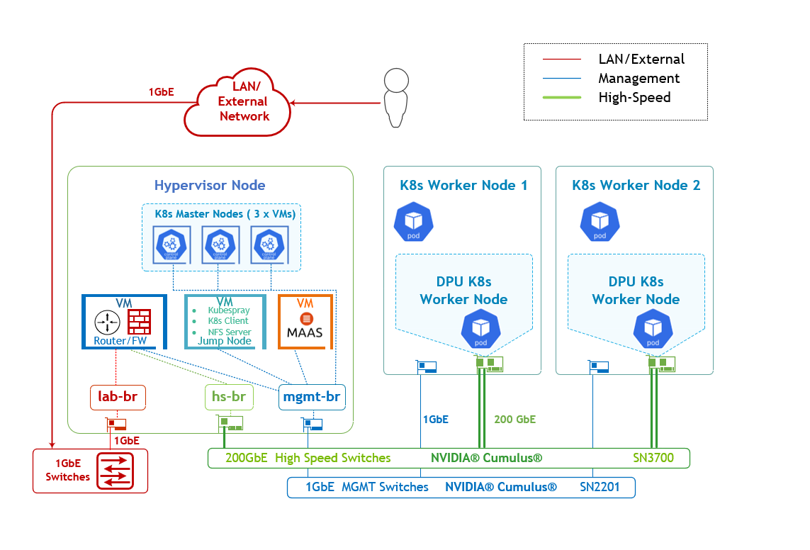
The logical design includes the following components:
1 x Hypervisor node (KVM based) with ConnectX-7
- 1 x Firewall VM
- 1 x Jump VM
- 1 x MaaS VM
- 3 x K8s Master VMs running all K8s management components
- 2 x Worker nodes (PCI Gen5), each with a 1 x BlueField-3 NIC
- Single High-Speed (HS) switch, 1 x L3 HS underlay network
- 1 Gb Host Management network
K8s Cluster Logical Design
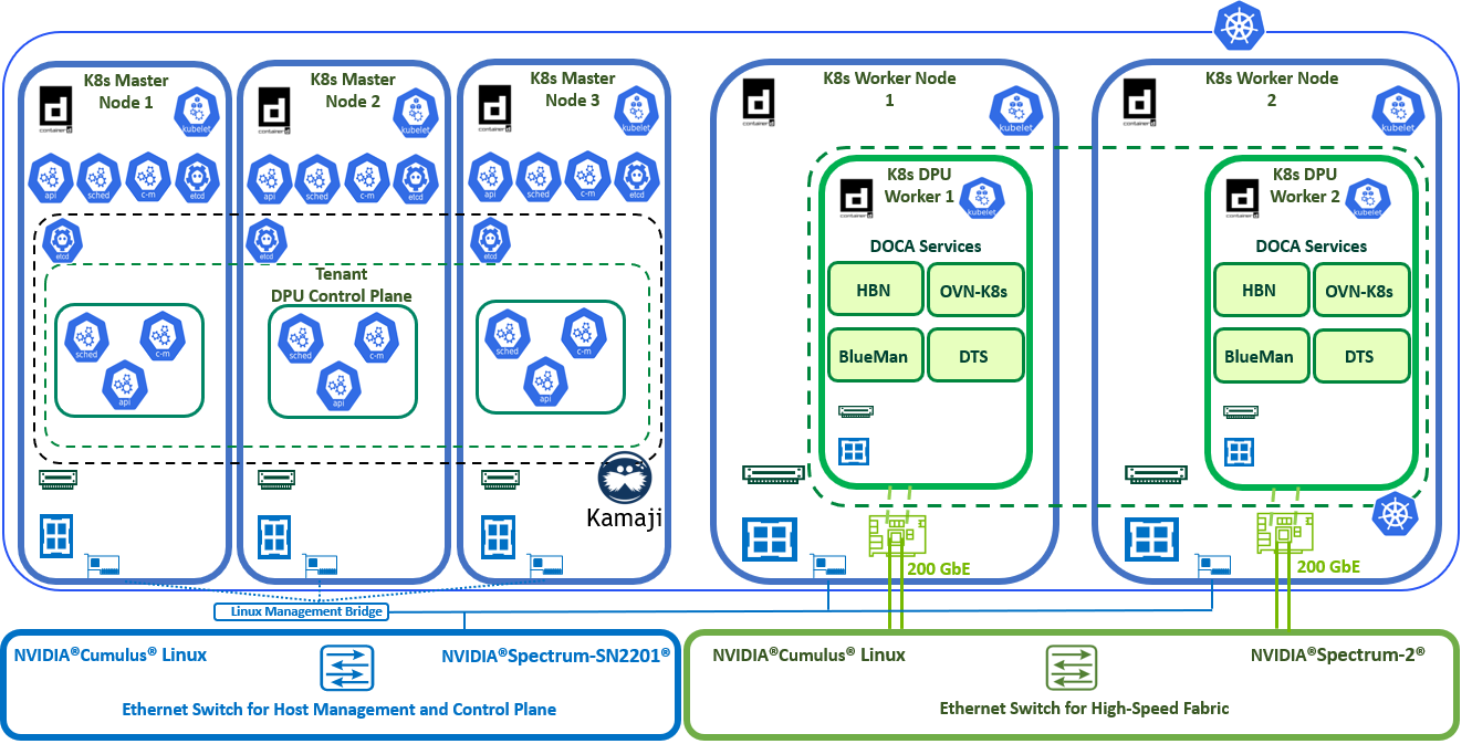
The following K8s logical design illustration demonstrates the main components of the DPF system, among them:
- 3 x K8s Master VMs running all K8s management components
- 2 x K8s Worker nodes (x86)
- 2 x K8s DPU Workers running DOCA services (OVN-K8s, HBN, DTS, BlueMan)
- 1 x Kamaji (K8s Control-Plane Manager)
- 1 x DPU Control Plane (Tenant Cluster)
- Connectivity to High-Speed/1Gb networks
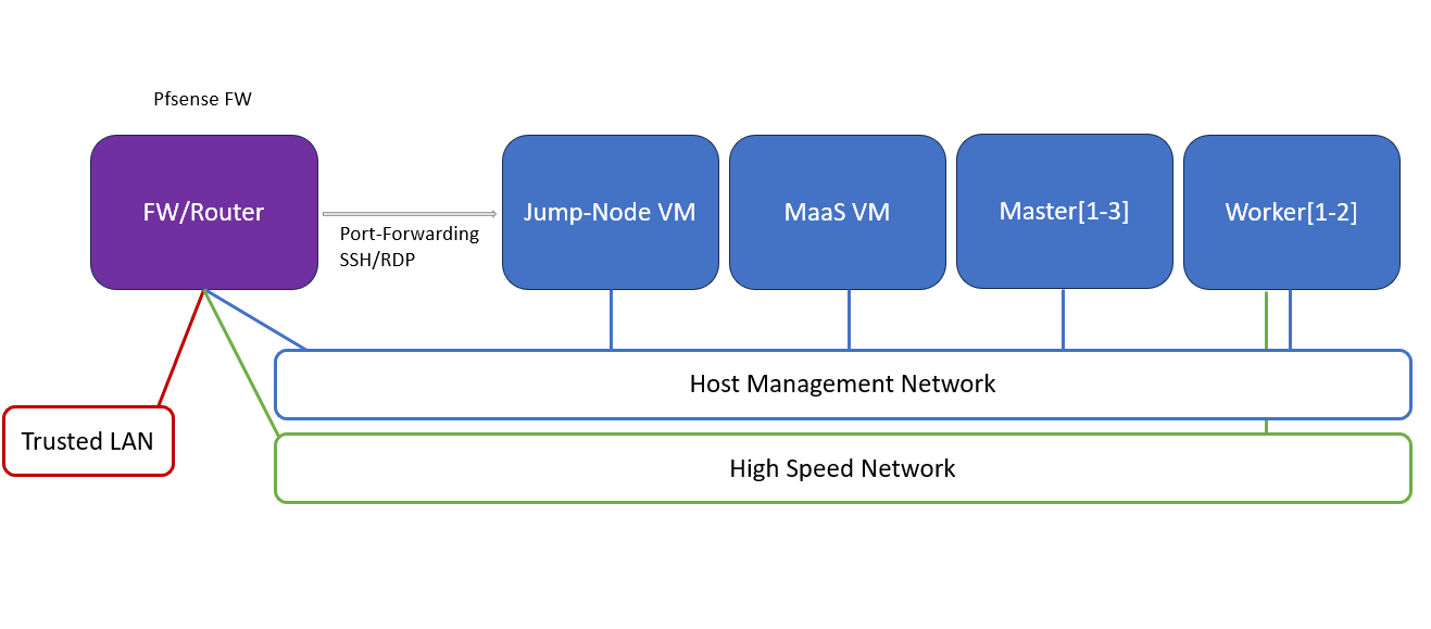
Firewall Design
The pfSense firewall in this solution serves a dual purpose:
- Firewall – provides an isolated environment for the DPF system, ensuring secure operations
- Router – enables internet access and connectivity between the host management network and the high-speed network
Port-forwarding rules for SSH and RDP are configured on the firewall to route traffic to the jump node’s IP address in the host management network. From the jump node, administrators can manage and access various devices in the setup, as well as handle the deployment of the Kubernetes (K8s) cluster and DPF components.
The following diagram illustrates the firewall design used in this solution:
Software Stack Components
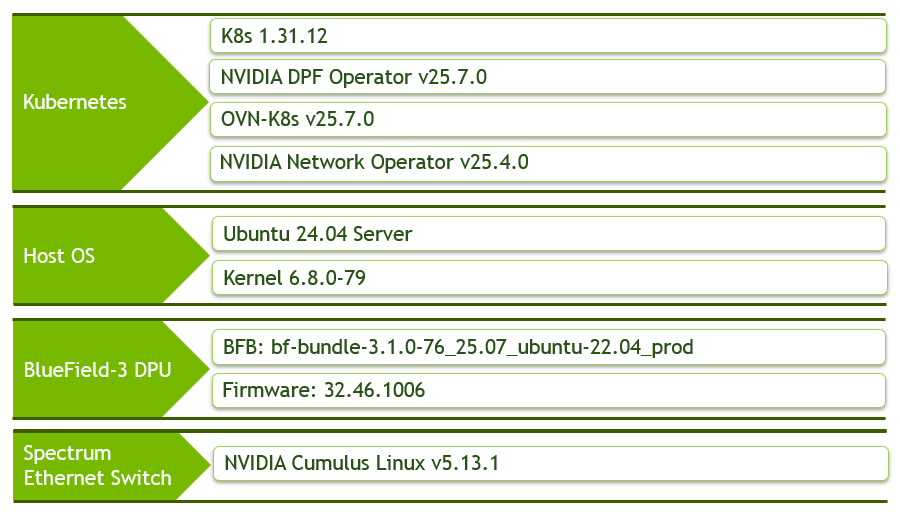
Make sure to use the exact same versions for the software stack as described above.
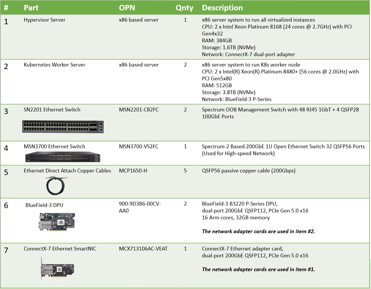
Bill of Materials
Deployment and Configuration
Node and Switch Definitions
These are the definitions and parameters used for deploying the demonstrated fabric:
Switch Port Usage | ||
Hostname | Rack ID | Ports |
| 1 | swp1,11-14 |
| 1 | swp1-3 |
Hosts | |||||
Rack | Server Type | Server Name | Switch Port | IP and NICs | Default Gateway |
Rack1 | Hypervisor Node |
| mgmt-switch: hs-switch: | lab-br (interface eno1): Trusted LAN IP mgmt-br (interface eno2): - hs-br (interface ens2f0np0): - | Trusted LAN GW |
Rack1 | Worker Node |
| mgmt-switch: hs-switch: | ens15f0: 10.0.110.21/24 ens5f0np0/ens5f1np1: 10.0.120.0/22 | 10.0.110.254 |
Rack1 | Worker Node |
| mgmt-switch: hs-switch: | ens15f0: 10.0.110.22/24 ens5f0np0/ens5f1np1: 10.0.120.0/22 | 10.0.110.254 |
Rack1 | Firewall (Virtual) |
| - | WAN (lab-br): Trusted LAN IP LAN (mgmt-br): 10.0.110.254/24 OPT1 (hs-br): 172.169.50.1/30 | Trusted LAN GW |
Rack1 | Jump Node (Virtual) |
| - | enp1s0: 10.0.110.253/24 | 10.0.110.254 |
Rack1 | MaaS (Virtual) |
| - | enp1s0: 10.0.110.252/24 | 10.0.110.254 |
Rack1 | Master Node (Virtual) |
| - | enp1s0: 10.0.110.1/24 | 10.0.110.254 |
Rack1 | Master Node (Virtual) |
| - | enp1s0: 10.0.110.2/24 | 10.0.110.254 |
Rack1 | Master Node (Virtual) |
| - | enp1s0: 10.0.110.3/24 | 10.0.110.254 |
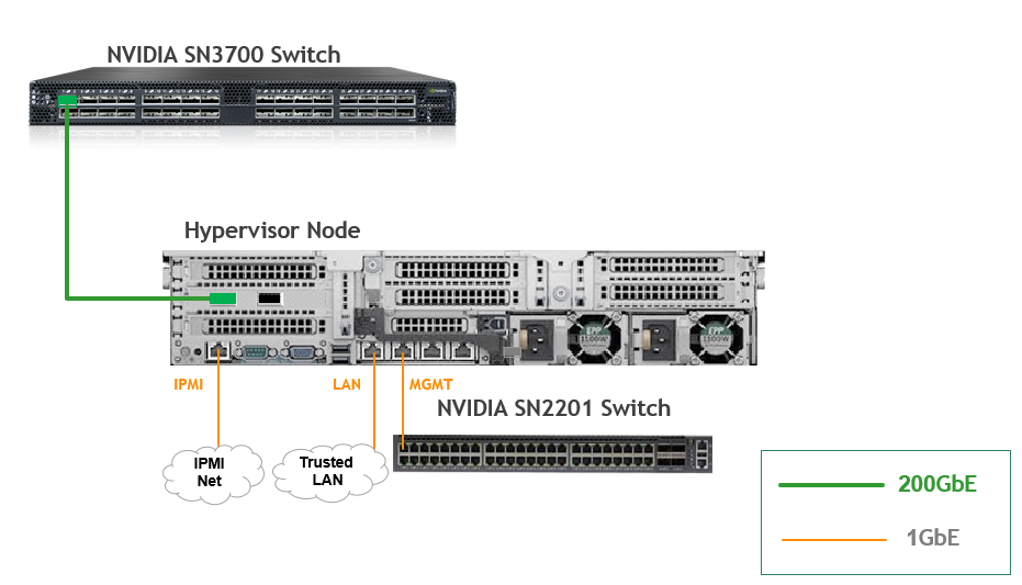
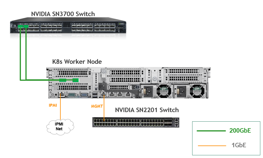
Wiring
Hypervisor Node
K8s Worker Node
Fabric Configuration
Updating Cumulus Linux
As a best practice, make sure to use the latest released Cumulus Linux NOS version.
For information on how to upgrade Cumulus Linux, refer to the Cumulus Linux User Guide.
Configuring the Cumulus Linux Switch
For the SN3700 switch (hs-switch), is configured as follows:
The following commands configure BGP unnumbered on
hs-switch.Cumulus Linux enables the BGP equal-cost multipathing (ECMP) option by default.
SN3700 Switch Console
            nv set interface lo ip address 11.0.0.101/32
nv set interface lo type loopback
nv set interface swp1 ip address 172.169.50.2/30
nv set interface swp1,11-14 link state up
nv set interface swp1,11-14 type swp
nv set router bgp autonomous-system 65001
nv set router bgp enable on
nv set router bgp graceful-restart mode full
nv set router bgp router-id 11.0.0.101
nv set vrf default router bgp address-family ipv4-unicast enable on
nv set vrf default router bgp address-family ipv4-unicast redistribute connected enable on
nv set vrf default router bgp address-family ipv4-unicast redistribute static enable on
nv set vrf default router bgp address-family ipv6-unicast enable on
nv set vrf default router bgp address-family ipv6-unicast redistribute connected enable on
nv set vrf default router bgp enable on
nv set vrf default router bgp neighbor swp11-14 peer-group hbn
nv set vrf default router bgp neighbor swp11-14 type unnumbered
nv set vrf default router bgp path-selection multipath aspath-ignore on
nv set vrf default router bgp peer-group hbn remote-as external
nv set vrf default router static 0.0.0.0/0 address-family ipv4-unicast
nv set vrf default router static 0.0.0.0/0 via 172.169.50.1 type ipv4-address
nv set vrf default router static 10.0.110.0/24 address-family ipv4-unicast
nv set vrf default router static 10.0.110.0/24 via 172.169.50.1 type ipv4-address
nv config apply -y
The SN2201 switch (mgmt-switch) is configured as follows:
SN2201 Switch Console
            nv set bridge domain br_default untagged 1
nv set interface swp1-3 link state up
nv set interface swp1-3 type swp
nv set interface swp1-3 bridge domain br_default
nv config apply -y
Host Configuration
Make sure that the BIOS settings on the worker node servers have SR-IOV enabled and that the servers are tuned for maximum performance.
All worker nodes must have the same PCIe placement for the BlueField-3 NIC and must show the same interface name.
Hypervisor Installation and Configuration
The hypervisor used in this Reference Deployment Guide (RDG) is based on Ubuntu 24.04 with KVM.
While this document does not detail the KVM installation process, it is important to note that the setup requires the following ISOs to deploy the Firewall, Jump, and MaaS virtual machines (VMs):
- Ubuntu 24.04
- pfSense-CE-2.7.2
To implement the solution, three Linux bridges must be created on the hypervisor:
Ensure a DHCP record is configured for the lab-br bridge interface in your trusted LAN to assign it an IP address.
lab-br– connects the Firewall VM to the trusted LAN.mgmt-br– Connects the various VMs to the host management network.hs-br– Connects the Firewall VM to the high-speed network.
Additionally, an MTU of 9000 must be configured on the management and high-speed bridges (mgmt-br and hs-br) as well as their uplink interfaces to ensure optimal performance.
Hypervisor netplan configuration
            network:
    ethernets:
        eno1:
            dhcp4: false
        eno2:
            dhcp4: false
            mtu: 9000
        ens2f0np0:
            dhcp4: false
            mtu: 9000
    bridges:
      lab-br:
         interfaces: [eno1]
         dhcp4: true
      mgmt-br:
         interfaces: [eno2]
         dhcp4: false
         mtu: 9000
      hs-br:
         interfaces: [ens2f0np0]
         dhcp4: false
         mtu: 9000
    version: 2
Apply the configuration:
Hypervisor Console
$ sudo netplan apply
Prepare Infrastructure Servers
Firewall VM - pfSense Installation and Interface Configuration
Download the pfSense CE (Community Edition) ISO to your hypervisor and proceed with the software installation.
Suggested spec:
- vCPU: 2
- RAM: 2GB
- Storage: 10GB
Network interfaces
- Bridge device connected to
lab-br - Bridge device connected to
mgmt-br - Bridge device connected to
hs-br
- Bridge device connected to
The Firewall VM must be connected to all three Linux bridges on the hypervisor. Before beginning the installation, ensure that three virtual network interfaces of type "Bridge device" are configured. Each interface should be connected to a different bridge (lab-br, mgmt-br, and hs-br) as illustrated in the diagram below.
After completing the installation, the setup wizard displays a menu with several options, such as "Assign Interfaces" and "Reboot System." During this phase, you must configure the network interfaces for the Firewall VM.
Select Option 2: "Set interface(s) IP address" and configure the interfaces as follows:
- WAN (lab-br) – Trusted LAN IP (Static/DHCP)
- LAN (mgmt-br) – Static IP
10.0.110.254/24 - OPT1 (hs-br) – Static IP
172.169.50.1/30
- Once the interface configuration is complete, use a web browser within the host management network to access the Firewall web interface and finalize the configuration.
Next, proceed with the installation of the Jump VM. This VM will serve as a platform for running a browser to access the Firewall’s web interface for post-installation configuration.
Jump VM
Suggested specifications:
- vCPU: 4
- RAM: 8GB
- Storage: 25GB
- Network interface: Bridge device, connected to
mgmt-br
Procedure:
Proceed with a standard Ubuntu 24.04 installation. Use the following login credentials across all hosts in this setup:
Username
Password
depuser
user
Enable internet connectivity and DNS resolution by creating the following Netplan configuration:
NoteUse
10.0.110.254as a temporary DNS nameserver until the MaaS VM is installed and configured. After completing the MaaS installation, update the Netplan file to replace this address with the MaaS IP:10.0.110.252.Jump Node netplan
network: ethernets: enp1s0: dhcp4:
falseaddresses: [10.0.110.253/24] nameservers: search: [dpf.rdg.local.domain] addresses: [10.0.110.254] routes: - to:defaultvia:10.0.110.254version:2Apply the configuration:
Jump Node Console
depuser@jump:~$ sudo netplan apply
Update and upgrade the system:
Jump Node Console
            depuser@jump:~$ sudo apt update -y
depuser@jump:~$ sudo apt upgrade -y
Install and configure the Xfce desktop environment and XRDP (complementary packages for RDP):
Jump Node Console
            depuser@jump:~$ sudo apt install -y xfce4 xfce4-goodies
depuser@jump:~$ sudo apt install -y lightdm-gtk-greeter
depuser@jump:~$ sudo apt install -y xrdp
depuser@jump:~$ echo "xfce4-session" | tee .xsession
depuser@jump:~$ sudo systemctl restart xrdp
Install Firefox for accessing the Firewall web interface:
Jump Node Console
$ sudo apt install -y firefox
Install and configure an NFS server with the
/mnt/dpf_sharedirectory:Jump Node Console
            $ sudo apt install -y nfs-server
$ sudo mkdir -m 777 /mnt/dpf_share
$ sudo vi /etc/exports
Add the following line to
/etc/exports:Jump Node Console
/mnt/dpf_share 10.0.110.0/24(rw,sync,no_subtree_check)
Restart the NFS server:
Jump Node Console
$ sudo systemctl restart nfs-server
Create the directory
bfbunder/mnt/dpf_sharewith the same permissions as the parent directory:Jump Node Console
$ sudo mkdir -m 777 /mnt/dpf_share/bfb
Generate an SSH key pair for
depuserin the jump node (later on will be imported to the admin user in MaaS to enable password-less login to the provisioned servers):Jump Node Console
depuser@jump:~$ ssh-keygen -t rsa
Reboot the jump node to display the graphical user interface:
Jump Node Console
depuser@jump:~$ sudo reboot
NoteAfter setting up port-forwarding rules on the firewall (next steps), remote login to the graphical interface of the Jump node will be available.
Concurrent login to the local graphical console and using RDP isn't possible, make sure to first log out from the local console when switching to RDP connection.
Firewall VM – Web Configuration
From your Jump node, open Firefox web browser and go to the pfSense web UI (http://10.0.110.254, default credentials are admin/pfsense). You should see a page similar to the following:
The IP addresses from the trusted LAN network under "DNS servers" and "Interfaces - WAN" are blurred.
Proceed with the following configurations:
The following screenshots display only a part of the configuration view. Make sure to not miss any of the steps mentioned below!
Interfaces
- WAN – mark “Enable interface”, unmark “Block private networks and loopback addresses”
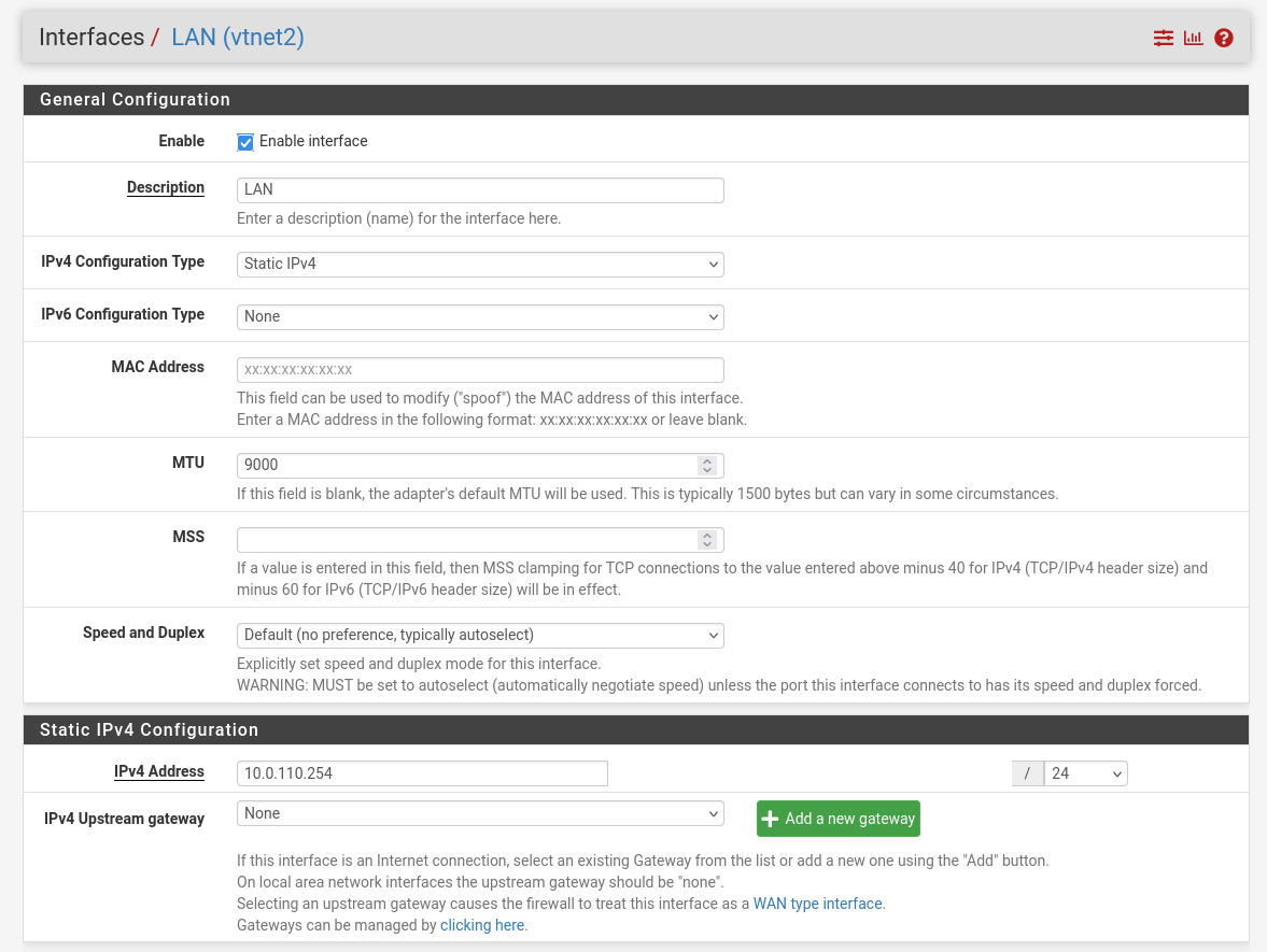
- LAN – mark “Enable interface”, “IPv4 configuration type”: Static IPv4 ("IPv4 Address": 10.0.110.254/24, "IPv4 Upstream Gateway": None), “MTU”: 9000
OPT1 – mark “Enable interface”, “IPv4 configuration type”: Static IPv4 ("IPv4 Address": 172.169.50.1/30, "IPv4 Upstream Gateway": None), “MTU”: 9000
Firewall:
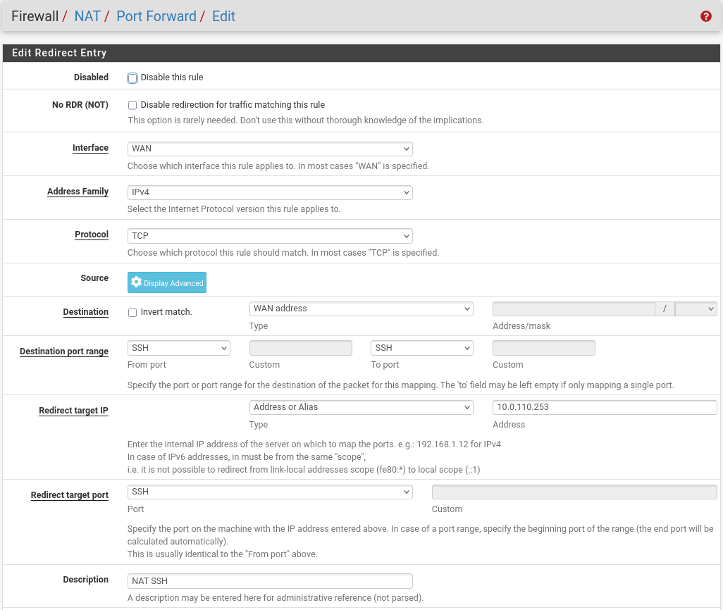
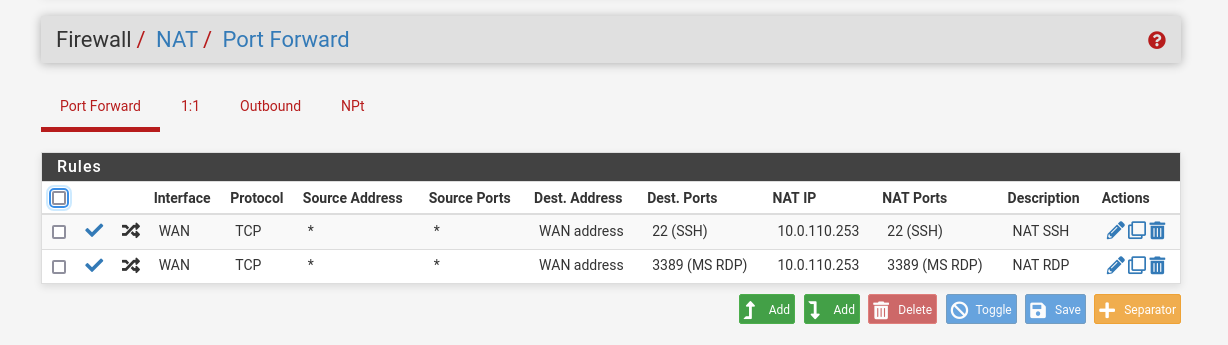
- NAT -> Port Forward -> Add rule -> “Interface”: WAN, “Address Family”: IPv4, “Protocol”: TCP, “Destination”: WAN address, “Destination port range”: (“From port”: SSH, “To port”: SSH), “Redirect target IP”: (“Type”: Address or Alias, “Address”: 10.0.110.253), “Redirect target port”: SSH, “Description”: NAT SSH
NAT -> Port Forward -> Add rule -> “Interface”: WAN, “Address Family”: IPv4, “Protocol”: TCP, “Destination”: WAN address, “Destination port range”: (“From port”: MS RDP, “To port”: MS RDP), “Redirect target IP”: (“Type”: Address or Alias, “Address”: 10.0.110.253), “Redirect target port”: MS RDP, “Description”: NAT RDP
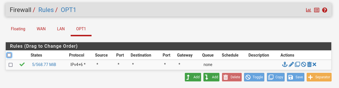
Rules -> OPT1 -> Add rule -> “Action”: Pass, “Interface”: OPT1, “Address Family”: IPv4+IPv6, “Protocol”: Any, “Source”: Any, “Destination”: Any
System:
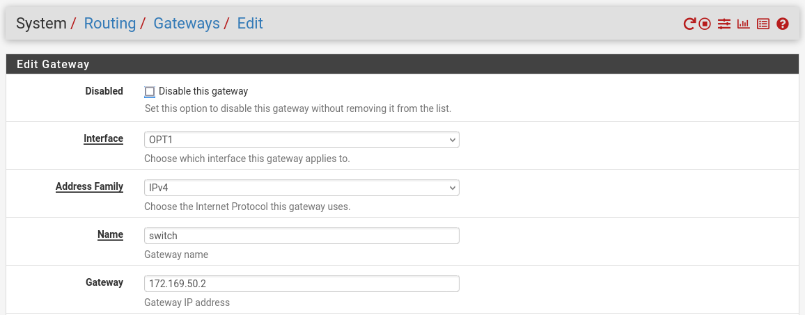
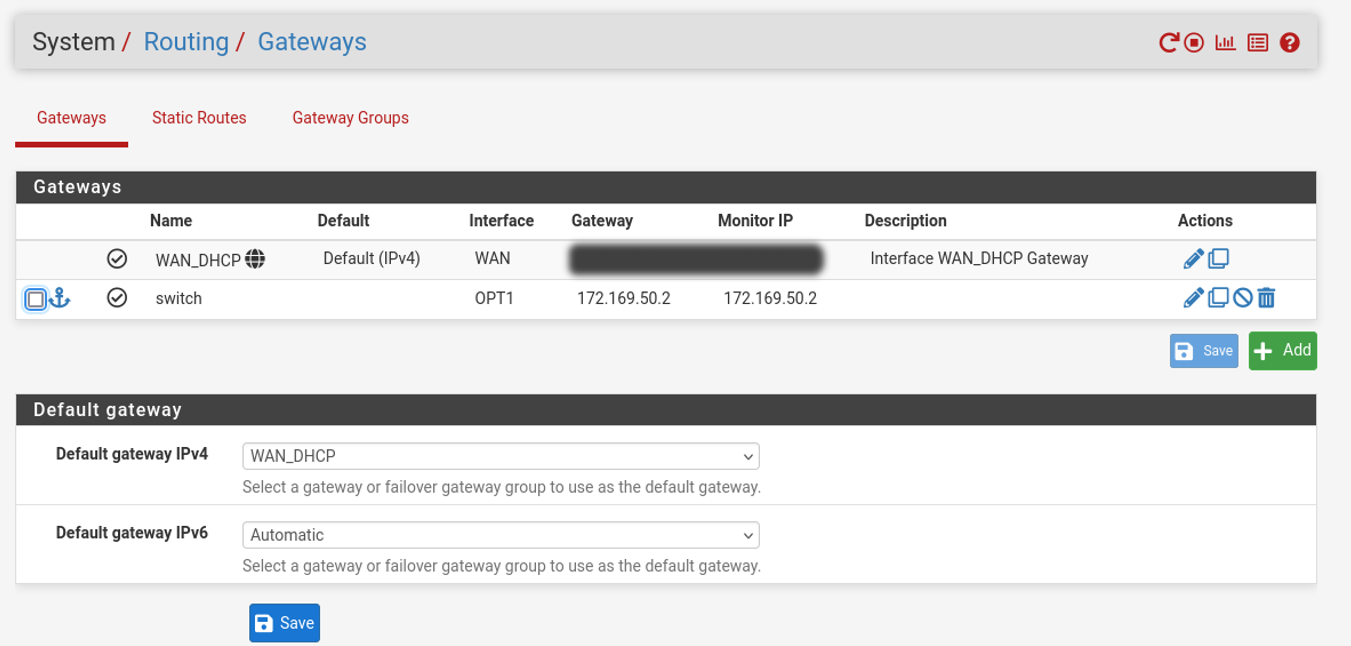
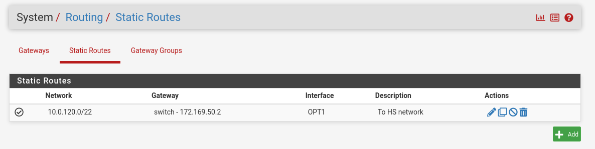
Routing → Gateways → Add → “Interface”: OPT1, “Address Family”: IPv4, “Name”: switch, “Gateway”: 172.169.50.2 → Click "Save"→ Under "Default Gateway" - "Default gateway IPv4" choose WAN_DHCP → Click "Save"
 Note
NoteNote that the IP addresses from the Trusted LAN network under "Gateway" and "Monitor IP" are blurred.
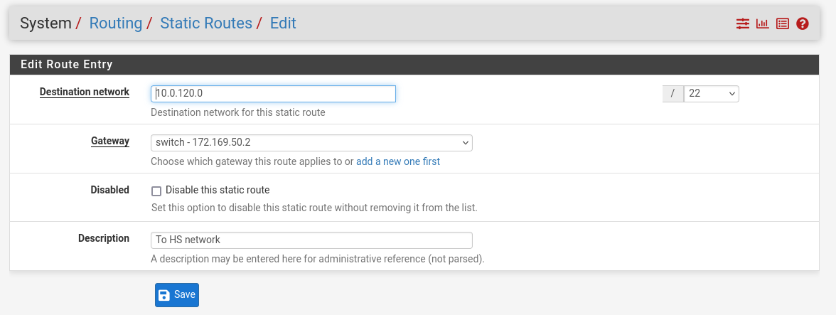
Routing → Static Routes → Add → “Destination network”: 10.0.120.0/22, “Gateway”: switch – 172.169.50.2, “Description”: To HS network → Click "Save"
MaaS VM
Suggested specifications:
- vCPU: 4
- RAM: 4GB
- Storage: 50GB
- Network interface: Bridge device, connected to
mgmt-br
Procedure:
- Perform a regular Ubuntu installation on the MaaS VM.
Create the following Netplan configuration to enable internet connectivity and DNS resolution:
NoteUse
10.0.110.254as a temporary DNS nameserver. After the MaaS installation, replace this with the MaaS IP address (10.0.110.252) in both the Jump and MaaS VM Netplan files.MaaS netplan
network: ethernets: enp1s0: dhcp4:
falseaddresses: [10.0.110.252/24] nameservers: search: [dpf.rdg.local.domain] addresses: [10.0.110.254] routes: - to:defaultvia:10.0.110.254version:2Apply the netplan configuration:
MaaS Console
depuser@maas:~$ sudo netplan apply
Update and upgrade the system:
MaaS Console
            depuser@maas:~$ sudo apt update -y
depuser@maas:~$ sudo apt upgrade -y
Install PostgreSQL and configure the database for MaaS:
MaaS Console
            $ sudo -i
# apt install -y postgresql
# systemctl enable --now postgresql
# systemctl disable --now systemd-timesyncd
# export MAAS_DBUSER=maasuser
# export MAAS_DBPASS=maaspass
# export MAAS_DBNAME=maas
# sudo -i -u postgres psql -c "CREATE USER \"$MAAS_DBUSER\" WITH ENCRYPTED PASSWORD '$MAAS_DBPASS'"
# sudo -i -u postgres createdb -O "$MAAS_DBUSER" "$MAAS_DBNAME"
Install MaaS:
MaaS Console
# snap install maas
Initialize MaaS:
MaaS Console
# maas init region+rack --maas-url http://10.0.110.252:5240/MAAS --database-uri "postgres://$MAAS_DBUSER:$MAAS_DBPASS@localhost/$MAAS_DBNAME"
Create an admin account:
MaaS Console
# maas createadmin --username admin --password admin --email admin@example.com
Save the admin API key:
MaaS Console
# maas apikey --username admin > admin-apikey
Log in to the MaaS server:
MaaS Console
# maas login admin http://localhost:5240/MAAS "$(cat admin-apikey)"
Configure MaaS (Substitute <Trusted_LAN_NTP_IP> and <Trusted_LAN_DNS_IP> with the IP addresses in your environment):
MaaS Console
            # maas admin domain update maas name="dpf.rdg.local.domain"
# maas admin maas set-config name=ntp_servers value="<Trusted_LAN_NTP_IP>"
# maas admin maas set-config name=network_discovery value="disabled"
# maas admin maas set-config name=upstream_dns value="<Trusted_LAN_DNS_IP>"
# maas admin maas set-config name=dnssec_validation value="no"
# maas admin maas set-config name=default_osystem value="ubuntu"
Define and configure IP ranges and subnets:
MaaS Console
            # maas admin ipranges create type=dynamic start_ip="10.0.110.51" end_ip="10.0.110.120"
# maas admin ipranges create type=reserved start_ip="10.0.110.10" end_ip="10.0.110.10" comment="c-plane VIP"
# maas admin ipranges create type=reserved start_ip="10.0.110.200" end_ip="10.0.110.200" comment="kamaji VIP"
# maas admin ipranges create type=reserved start_ip="10.0.110.251" end_ip="10.0.110.254" comment="dpfmgmt"
# maas admin vlan update 0 untagged dhcp_on=True primary_rack=maas mtu=9000
# maas admin dnsresources create fqdn=kube-vip.dpf.rdg.local.domain ip_addresses=10.0.110.10
# maas admin dnsresources create fqdn=jump.dpf.rdg.local.domain ip_addresses=10.0.110.253
# maas admin dnsresources create fqdn=fw.dpf.rdg.local.domain ip_addresses=10.0.110.254
# maas admin fabrics create
Success.
Machine-readable output follows:
{
"class_type": null,
"name": "fabric-1",
"id": 1,
...
# maas admin subnets create name="fake-dpf" cidr="20.20.20.0/24" fabric=1
Configure static DHCP leases for the worker nodes (replace MAC address as appropriate with your workers MGMT interface MAC):
MaaS Console
            # maas admin reserved-ips create ip="10.0.110.21" mac_address="04:32:01:60:0d:da" comment="worker1"
# maas admin reserved-ips create ip="10.0.110.22" mac_address="04:32:01:5f:cb:e0" comment="worker2"
Complete MaaS setup:
- Connect to the Jump node GUI and access the MaaS UI at
http://10.0.110.252:5240/MAAS. - On the first page, verify the "Region Name" and "DNS Forwarder," then continue.
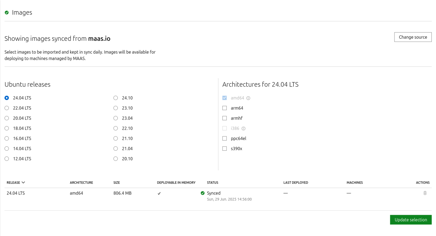
On the image selection page, verify that Ubuntu 24.04 LTS (amd64) image is synced and continue.
Import the previously generated SSH key (
id_rsa.pub) for thedepuserinto the MaaS admin user profile and finalize the setup.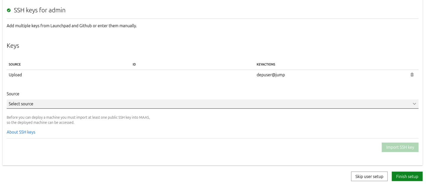
- Connect to the Jump node GUI and access the MaaS UI at
- Update the DNS nameserver IP address in both Jump and MaaS VM Netplan files from
10.0.110.254to10.0.110.252and reapply the configuration.
K8s Master VMs
Suggested specifications:
- vCPU: 8
- RAM: 16GB
- Storage: 100GB
- Network interface: Bridge device, connected to
mgmt-br
Before provisioning the Kubernetes (K8s) Master VMs with MaaS, create the required virtual disks with empty storage. Use the following one-liner to create three 100 GB QCOW2 virtual disks:
Hypervisor Console
$ for i in $(seq 1 3); do qemu-img create -f qcow2 /var/lib/libvirt/images/master$i.qcow2 100G; done
This command generates the following disks in the
/var/lib/libvirt/images/directory:master1.qcow2master2.qcow2master3.qcow2
Configure VMs in virt-manager:
Open virt-manager and create three virtual machines:
- Assign the corresponding virtual disk (
master1.qcow2,master2.qcow2, ormaster3.qcow2) to each VM. - Configure each VM with the suggested specifications (vCPU, RAM, storage, and network interface).
- Assign the corresponding virtual disk (
- During the VM setup, ensure the NIC is selected under the Boot Options tab. This ensures the VMs can PXE boot for MaaS provisioning.
- Once the configuration is complete, shut down all the VMs.
- After the VMs are created and configured, proceed to provision them via the MaaS interface. MaaS will handle the OS installation and further setup as part of the deployment process.
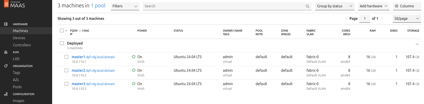
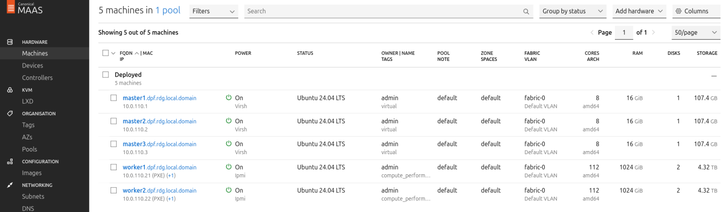
Provision Master VMs and Worker Nodes Using MaaS
Master VMs
Install virsh and Set Up SSH Access
SSH to the MaaS VM from the Jump node:
MaaS Console
            depuser@jump:~$ ssh maas
depuser@maas:~$ sudo -i
Install the
virshclient to communicate with the hypervisor:MaaS Console
# apt install -y libvirt-clients
Generate an SSH key for the
rootuser and copy it to the hypervisor user in thelibvirtdgroup:MaaS Console
            # ssh-keygen -t rsa
# ssh-copy-id ubuntu@<hypervisor_MGMT_IP>
Verify SSH access and
virshcommunication with the hypervisor:MaaS Console
# virsh -c qemu+ssh://ubuntu@<hypervisor_MGMT_IP>/system list --all
Expected output:
MaaS Console
             Id   Name          State
------------------------------
 1    fw     running
 2    jump   running
 3    maas   running
 -    master1       shut off
 -    master2       shut off
 -    master3       shut off
Copy the SSH key to the required MaaS directory (for snap-based installations):
MaaS Console
            # mkdir -p /var/snap/maas/current/root/.ssh
# cp .ssh/id_rsa* /var/snap/maas/current/root/.ssh/
Get MAC Addresses of the Master VMs
Retrieve the MAC addresses of the Master VMs:
MaaS Console
# for i in $(seq 1 3); do virsh -c qemu+ssh://ubuntu@<hypervisor_MGMT_IP>/system dumpxml master$i | grep 'mac address'; done
Example output:
MaaS Console
            <mac address='52:54:00:a9:9c:ef'/>
<mac address='52:54:00:19:6b:4d'/>
<mac address='52:54:00:68:39:7f'/>
Add Master VMs to MaaS
Add the Master VMs to MaaS:
InfoOnce added, MaaS will automatically start the newly added VMs commissioning (discovery and introspection).
MaaS Console
            # maas admin machines create hostname=master1 architecture=amd64/generic mac_addresses='52:54:00:a9:9c:ef' power_type=virsh power_parameters_power_address=qemu+ssh://ubuntu@<hypervisor_MGMT_IP>/system power_parameters_power_id=master1 skip_bmc_config=1 testing_scripts=none
Success.
Machine-readable output follows:
{
    "description": "",
    "status_name": "Commissioning",
...
    "status": 1,
...
    "system_id": "c3seyq",
...
    "fqdn": "master1.dpf.rdg.local.domain",
    "power_type": "virsh",
...
    "status_message": "Commissioning",
    "resource_uri": "/MAAS/api/2.0/machines/c3seyq/"
}

# maas admin machines create hostname=master2 architecture=amd64/generic mac_addresses='52:54:00:19:6b:4d' power_type=virsh power_parameters_power_address=qemu+ssh://ubuntu@<hypervisor_MGMT_IP>/system power_parameters_power_id=master2 skip_bmc_config=1 testing_scripts=none

# maas admin machines create hostname=master3 architecture=amd64/generic mac_addresses='52:54:00:68:39:7f' power_type=virsh power_parameters_power_address=qemu+ssh://ubuntu@<hypervisor_MGMT_IP>/system power_parameters_power_id=master3 skip_bmc_config=1 testing_scripts=none
Repeat the command for
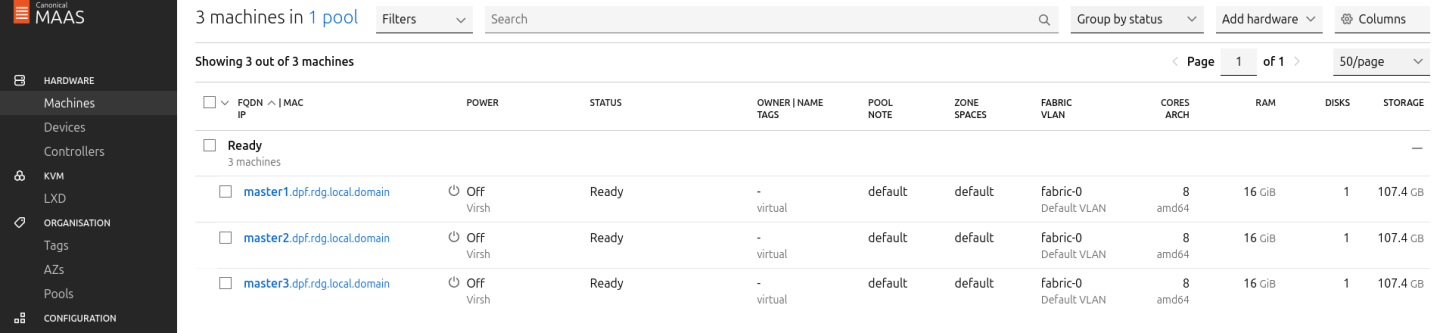
master2andmaster3with their respective MAC addresses.Verify commissioning by waiting for the status to change to "Ready" in MaaS.
After commissioning, the next phase is the deployment (OS provisioning).
Configure OVS Bridges on Master VMs
To be able to have persistency across reboots, create an OVS-bridge from each management interface of the master nodes and assign it a static IP address.
For each Master VM:
Create an OVS bridge in the MaaS Network tab:
- Navigate to Network → Management Interface → Create Bridge.
Configure as follows:
- Name:
brenp1s0(prefixbradded to the interface name) - Bridge Type: Open vSwitch (ovs)
- Subnet: 10.0.110.0/24
- IP Mode: Static (Client configured)
Address: Assign
10.0.110.1formaster1,10.0.110.2formaster2, and10.0.110.3formaster3.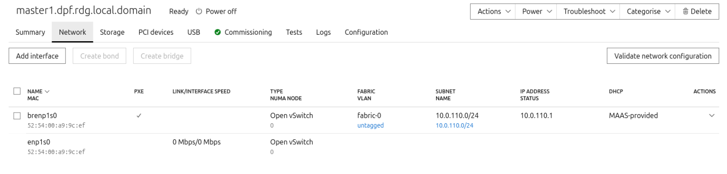
- Name:
- Save the interface settings for each VM.
Deploy Master VMs Using Cloud-Init
Use the following cloud-init script to configure the necessary software and ensure OVS bridge persistency:
NoteReplace
enp1s0andbrenp1s0in the following cloud-init with your interface names as displayed in MaaS network tab.Master nodes cloud-init
#cloud-config system_info: default_user: name: depuser passwd:
"$6$jOKPZPHD9XbG72lJ$evCabLvy1GEZ5OR1Rrece3NhWpZ2CnS0E3fu5P1VcZgcRO37e4es9gmriyh14b8Jx8gmGwHAJxs3ZEjB0s0kn/"lock_passwd:falsegroups: [adm, audio, cdrom, dialout, dip, floppy, lxd, netdev, plugdev, sudo, video] sudo: ["ALL=(ALL) NOPASSWD:ALL"] shell: /bin/bash ssh_pwauth: True package_upgrade:trueruncmd: - apt-get update - apt-get -y install openvswitch-switchnfs-common - | UPLINK_MAC=$(cat /sys/class/net/enp1s0/address) ovs-vsctl set Bridge brenp1s0 other-config:hwaddr=$UPLINK_MAC ovs-vsctl br-set-external-id brenp1s0 bridge-id brenp1s0 -- br-set-external-id brenp1s0 bridge-uplink enp1s0Deploy the master VMs:
- Select all three Master VMs → Actions → Deploy.
- Toggle Cloud-init user-data and paste the cloud-init script.
Start the deployment and wait for the status to change to "Ubuntu 24.04 LTS".
Verify Deployment
SSH into the Master VMs from the Jump node:
Jump Node Console
            depuser@jump:~$ ssh master1
depuser@master1:~$
Run
sudowithout password:Master1 Console
            depuser@master1:~$ sudo -i
root@master1:~#
Verify installed packages:
Master1 Console
            root@master1:~# apt list --installed | egrep 'openvswitch-switch|nfs-common'
nfs-common/noble-updates,now 1:2.6.4-3ubuntu5.1 amd64 [installed]
openvswitch-switch/noble-updates,noble-security,noble-security,now 3.3.0-1ubuntu3.2 amd64 [installed]
Check OVS bridge attributes:
Master1 Console
root@master1:~# ovs-vsctl list bridge brenp1s0
Output example:
Master1 Console
            ...
external_ids        : {bridge-id=brenp1s0, bridge-uplink=enp1s0, netplan="true", "netplan/global/set-fail-mode"=standalone, "netplan/mcast_snooping_enable"="false", "netplan/rstp_enable"="false"}
...
other_config        : {hwaddr="52:54:00:a9:9c:ef"}
...
Verify that
enp1s0andbrenp1s0are configured with 9000 MTU (replaceenp1s0andbrenp1s0with your interface names):Master1 Console
            root@master1:~# ip a show enp1s0; ip a show brenp1s0
2: enp1s0: <BROADCAST,MULTICAST,UP,LOWER_UP> mtu 9000 qdisc pfifo_fast master ovs-system state UP group default qlen 1000
    link/ether 52:54:00:a9:9c:ef brd ff:ff:ff:ff:ff:ff
4: brenp1s0: <BROADCAST,MULTICAST,UP,LOWER_UP> mtu 9000 qdisc noqueue state UNKNOWN group default qlen 1000
    link/ether 52:54:00:a9:9c:ef brd ff:ff:ff:ff:ff:ff
    inet 10.0.110.1/24 brd 10.0.110.255 scope global brenp1s0
       valid_lft forever preferred_lft forever
    inet6 fe80::5054:ff:fea9:9cef/64 scope link
       valid_lft forever preferred_lft forever
Finalize Setup
Reboot the Master VMs to complete the provisioning.
Master1 Console
root@master1:~# reboot
Worker Nodes
Create Worker Machines in MaaS
Add the worker nodes to MaaS using
ipmias the power type. Replace placeholders with your specific IPMI credentials and IP addresses:MaaS Console
# maas admin machines create hostname=worker1 architecture=amd64 power_type=ipmi power_parameters_power_driver=LAN_2_0 power_parameters_power_user=<IPMI_username_worker1> power_parameters_power_pass=<IPMI_password_worker1> power_parameters_power_address=<IPMI_address_worker1> power_parameters_workaround_flags=opensesspriv power_parameters_workaround_flags=nochecksumcheck
Output example:
MaaS Console
            ...
Success.
Machine-readable output follows:
{
    "description": "",
    "status_name": "Commissioning",
...
    "status": 1,
...
    "system_id": "pbskd3",
...
    "fqdn": "worker1.dpf.rdg.local.domain",
...
    "power_type": "ipmi",
...
    "resource_uri": "/MAAS/api/2.0/machines/pbskd3/"
}
Repeat the command for
worker2with its respective credentials:MaaS Console
# maas admin machines create hostname=worker2 architecture=amd64 power_type=ipmi power_parameters_power_driver=LAN_2_0 power_parameters_power_user=<IPMI_username_worker2> power_parameters_power_pass=<IPMI_password_worker2> power_parameters_power_address=<IPMI_address_worker2> power_parameters_workaround_flags=opensesspriv power_parameters_workaround_flags=nochecksumcheck
Once added, MaaS will automatically start commissioning the worker nodes (discovery and introspection).
Create a Tag for Kernel Parameters
Create an entity called "Tag" to configure kernel parameters for the worker nodes.
In the MaaS UI sidebar, go to Organization → Tags → Create New Tag and define
- "Tag name":
compute_performance - "Kernel options":
- "Tag name":
Substitute the values for
isolcpus,nohz_full, andrcu_nocbsto the CPU cores in the NUMA node which the BlueField-3 is connected to:NoteIf you are not sure in which NUMA node BlueField is connected to, select the worker node in the Machines tab, go to Network settings and check the value under TYPE NUMA NODE.
Kernel options for worker nodes
intel_iommu=on iommu=pt numa_balancing=disable processor.max_cstate=0 isolcpus=28-55,84-111 nohz_full=28-55,84-111 rcu_nocbs=28-55,84-111
Apply the tag:
- Go to Machines → Select a worker node → Configuration → Edit Tag → Select
compute_performance→ Save. - Repeat for the other worker node.
- Go to Machines → Select a worker node → Configuration → Edit Tag → Select
Adjust Network Settings
For each worker node, configure the network interfaces:
Management Adapter:
- Go to Network → Select the host management adapter (e.g.,
ens15f0) → Create Bridge - Name:
br-dpu - Bridge Type: Standard
- Subnet:
10.0.110.0/24 - IP Mode: Dynamic
- Save the interface
- Go to Network → Select the host management adapter (e.g.,
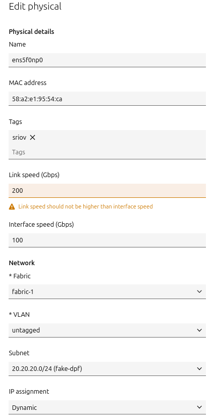
BlueField Adapter:
- Select
P0on the BlueField adapter (e.g.,ens5f0np0) → Actions → Edit Physical - Fabric:
Fabric-1 - Subnet:
20.20.20.0/24(fake-dpf) - IP Mode: Dynamic
- Save the interface
- Select
Repeat these steps for the second worker node.
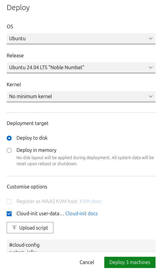
Deploy Worker Nodes Using Cloud-Init
Use the following cloud-init script for deployment. Replace
ens5f0np0with your actual interface name:Worker node cloud-init
#cloud-config system_info: default_user: name: depuser passwd:
"$6$jOKPZPHD9XbG72lJ$evCabLvy1GEZ5OR1Rrece3NhWpZ2CnS0E3fu5P1VcZgcRO37e4es9gmriyh14b8Jx8gmGwHAJxs3ZEjB0s0kn/"lock_passwd:falsegroups: [adm, audio, cdrom, dialout, dip, floppy, lxd, netdev, plugdev, sudo, video] sudo: ["ALL=(ALL) NOPASSWD:ALL"] shell: /bin/bash ssh_pwauth: True package_upgrade:truewrite_files: - path: /etc/sysctl.d/99-custom-netfilter.conf owner: root:root permissions:'0644'content: | net.bridge.bridge-nf-call-iptables=0runcmd: - apt-get update - apt-get -y install nfs-common - sysctl --system - sed -i'/^\s*ens5f0np0:/,/^\s*mtu:/ { /^\s*mtu:/d }'/etc/netplan/*.yaml - netplan apply- Deploy the worker nodes by selecting the worker nodes in MaaS → Actions → Deploy → Customize options → Enable Cloud-init user-data → Paste the cloud-init script → Deploy.
Verify Deployment
After the deployment is complete verify that the worker nodes have been deployed successfully with the following commands:
SSH without password from the jump node:
Jump Node Console
            depuser@jump:~$ ssh worker1
depuser@worker1:~$
Run
sudowithout password:Worker1 Console
            depuser@worker1:~$ sudo -i
root@worker1:~#
Validate that
nfs-commonpackage was installed:Worker1 Console
            root@worker1:~# apt list --installed | grep 'nfs-common'
nfs-common/noble-updates,now 1:2.6.4-3ubuntu5.1 amd64 [installed]
/proc/cmdlineis configured with the correct parameters and that IOMMU is indeed inpassthroughmode:Worker1 Console
            root@worker1:~# cat /proc/cmdline
BOOT_IMAGE=/boot/vmlinuz-6.8.0-79-generic root=UUID=d2365b16-d371-4503-a583-a1768dd27e0c ro intel_iommu=on iommu=pt numa_balancing=disable processor.max_cstate=0 isolcpus=28-55,84-111 nohz_full=28-55,84-111 rcu_nocbs=28-55,84-111

root@worker1:~# dmesg | grep 'type: Passthrough'
[    5.033173] iommu: Default domain type: Passthrough (set via kernel command line)
br_netfiltermodule is not loaded:Worker1 Console
            root@worker1:~# lsmod | grep br_netfilter
root@worker1:~#
P0 interface has
dhcp4set totrueand does not havemtuline innetplanconfiguration file.Worker1 Console
            root@worker1:~# cat /etc/netplan/50-cloud-init.yaml
network:
...
		ens5f0np0:
            dhcp4: true
            match:
                macaddress: "58:a2:e1:95:54:ca"
            set-name: "ens5f0np0"
...
ens15f0andbr-dpuare with 9000 MTU (replaceens15f0with your interface name):Worker1 Console
            root@worker1:~# ip a show ens15f0; ip a show br-dpu
2: ens15f0: <BROADCAST,MULTICAST,UP,LOWER_UP> mtu 9000 qdisc mq master br-dpu state UP group default qlen 1000
    link/ether 04:32:01:60:0d:da brd ff:ff:ff:ff:ff:ff
    altname enp53s0f0
8: br-dpu: <BROADCAST,MULTICAST,UP,LOWER_UP> mtu 9000 qdisc noqueue state UP group default qlen 1000
    link/ether 04:32:01:60:0d:da brd ff:ff:ff:ff:ff:ff
    inet 10.0.110.21/24 metric 100 brd 10.0.110.255 scope global dynamic br-dpu
       valid_lft 403sec preferred_lft 403sec
    inet6 fe80::632:1ff:fe60:dda/64 scope link
       valid_lft forever preferred_lft forever
Finalize Deployment
Reboot the worker nodes:
Jump Node Console
root@worker1:~# reboot
The infrastructure is now ready for the K8s deployment.
K8s Cluster Deployment and Configuration
Kubespray Deployment and Configuration
In this solution, the Kubernetes (K8s) cluster is deployed using a modified Kubespray (based on release v2.28.1) with a non-root depuser account from the Jump Node. The modifications in Kubespray are designed to meet the DPF prerequisites as described in the User Manual and facilitate cluster deployment and scaling.
- Download the modified Kubespray archive: modified_kubespray_v2.28.1.tar.gz.
Extract the contents and navigate to the extracted directory:
Jump Node Console
            $ tar -xzf /home/depuser/modified_kubespray_v2.28.1.tar.gz
$ cd kubespray/
depuser@jump:~/kubespray$
Set the K8s API VIP address and DNS record. Replace it with your own IP address and DNS record if different:
Jump Node Console
            depuser@jump:~/kubespray$ sed -i '/# kube_vip_address:/s/.*/kube_vip_address: 10.0.110.10/' inventory/mycluster/group_vars/k8s_cluster/addons.yml
depuser@jump:~/kubespray$ sed -i '/apiserver_loadbalancer_domain_name:/s/.*/apiserver_loadbalancer_domain_name: "kube-vip.dpf.rdg.local.domain"/' roles/kubespray_defaults/defaults/main/main.yml
Install the necessary dependencies and set up the Python virtual environment:
Jump Node Console
            depuser@jump:~/kubespray$ sudo apt -y install python3-pip jq python3.12-venv
depuser@jump:~/kubespray$ python3 -m venv .venv
depuser@jump:~/kubespray$ source .venv/bin/activate
(.venv) depuser@jump:~/kubespray$ python3 -m pip install --upgrade pip
(.venv) depuser@jump:~/kubespray$ pip install -U -r requirements.txt
(.venv) depuser@jump:~/kubespray$ pip install ruamel-yaml
Review and edit the
inventory/mycluster/hosts.yamlfile to define the cluster nodes. The following is the configuration for this deployment:NoteAll of the nodes are already labeled and annotated as per DPF user manual prerequisites.
The worker nodes include additional kubelet configuration which will be applied during their deployment to achieve best performance, allowing:
Containers in Guaranteed pods with integer CPU requests access to exclusive CPUs on the node.
Reserve some cores for the system using the
reservedSystemCPUsoption (kubelet requires a CPU reservation greater than zero to be made when the static policy is enabled), and make sure they belong to NUMA 0 (because the NIC in the example is wired to NUMA node 1, use cores from NUMA 1 if the NIC is wired to NUMA node 0).Define the topology to be
single-numa-nodeso it only allows a pod to be admitted if all requested CPUs and devices can be allocated from exactly one NUMA node.
The
kube_nodehostsworker1andworker2are marked with # to only deploy the cluster with control plane nodes at the beginning (worker nodes will be added later on after the various components that are necessary for the DPF system are installed).
inventory/mycluster/hosts.yaml
all: hosts: master1: ansible_host:
10.0.110.1ip:10.0.110.1access_ip:10.0.110.1node_labels:"k8s.ovn.org/zone-name":"master1"master2: ansible_host:10.0.110.2ip:10.0.110.2access_ip:10.0.110.2node_labels:"k8s.ovn.org/zone-name":"master2"master3: ansible_host:10.0.110.3ip:10.0.110.3access_ip:10.0.110.3node_labels:"k8s.ovn.org/zone-name":"master3"worker1: ansible_host:10.0.110.21ip:10.0.110.21access_ip:10.0.110.21node_labels:"node-role.kubernetes.io/worker":"""k8s.ovn.org/dpu-host":"""k8s.ovn.org/zone-name":"worker1"node_annotations:"k8s.ovn.org/remote-zone-migrated":"worker1"kubelet_cpu_manager_policy:statickubelet_topology_manager_policy: single-numa-node kubelet_reservedSystemCPUs:0-7worker2: ansible_host:10.0.110.22ip:10.0.110.22access_ip:10.0.110.22node_labels:"node-role.kubernetes.io/worker":"""k8s.ovn.org/dpu-host":"""k8s.ovn.org/zone-name":"worker2"node_annotations:"k8s.ovn.org/remote-zone-migrated":"worker2"kubelet_cpu_manager_policy:statickubelet_topology_manager_policy: single-numa-node kubelet_reservedSystemCPUs:0-7children: kube_control_plane: hosts: master1: master2: master3: kube_node: hosts: # worker1: # worker2: etcd: hosts: master1: master2: master3: k8s_cluster: children: kube_control_plane: kube_node:
Deploying Cluster Using Kubespray Ansible Playbook
Run the following command from the Jump Node to initiate the deployment process:
NoteEnsure you are in the Python virtual environment (
.venv) when running the command.Jump Node Console
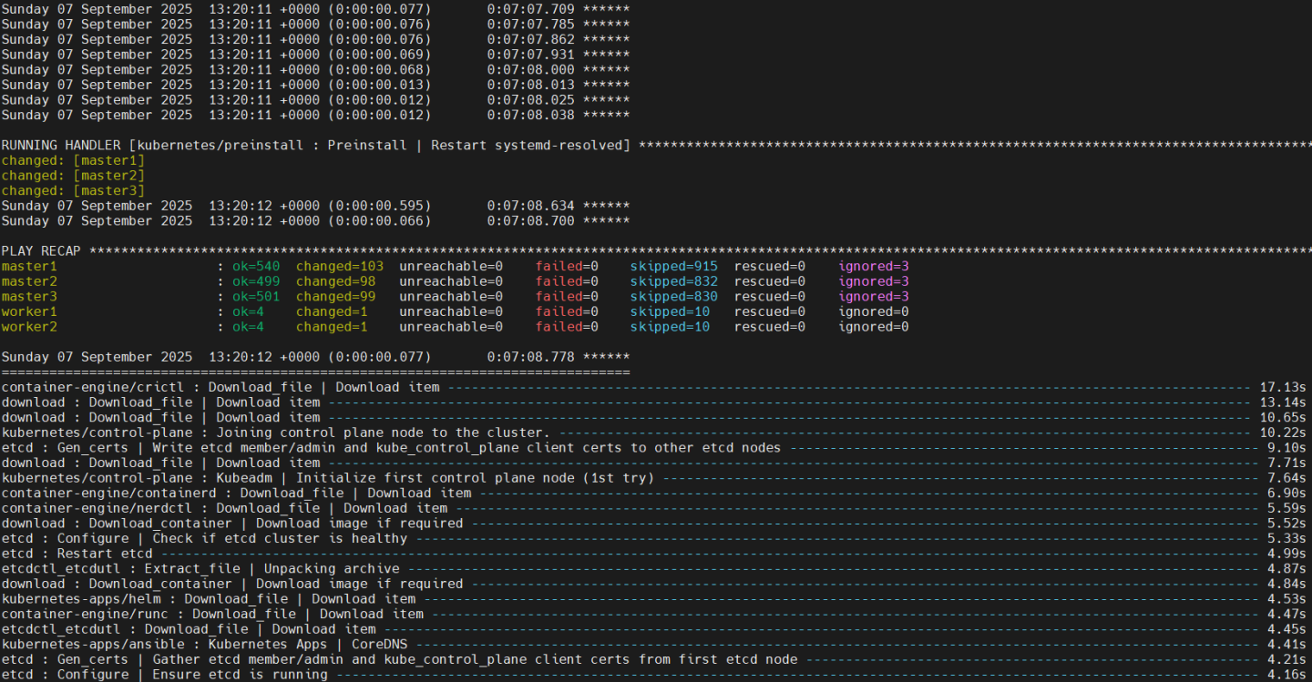
(.venv) depuser@jump:~/kubespray$ ansible-playbook -i inventory/mycluster/hosts.yaml --become --become-user=root cluster.yml
It takes a while for this deployment to complete. Make sure there are no errors. Successful result example:
 Tip
TipIt is recommended to keep the shell from which Kubespray has been running open, later on it will be useful when performing cluster scale out to add the worker nodes.
K8s Deployment Verification
To simplify managing the K8s cluster from the Jump Host, set up kubectl with bash auto-completion.
Copy
kubectland the kubeconfig file frommaster1to the Jump Host:Jump Node Console
            ## Connect to master1
depuser@jump:~$ ssh master1
depuser@master1:~$ cp /usr/local/bin/kubectl /tmp/
depuser@master1:~$ sudo cp /root/.kube/config /tmp/kube-config
depuser@master1:~$ sudo chmod 644 /tmp/kube-config
In another terminal tab, copy the files to the Jump Host:
Jump Node Console
            depuser@jump:~$ scp master1:/tmp/kubectl /tmp/
depuser@jump:~$ sudo chown root:root /tmp/kubectl
depuser@jump:~$ sudo mv /tmp/kubectl /usr/local/bin/
depuser@jump:~$ mkdir -p ~/.kube
depuser@jump:~$ scp master1:/tmp/kube-config ~/.kube/config
depuser@jump:~$ chmod 600 ~/.kube/config
Enable bash auto-completion for
kubectl:Verify if bash-completion is installed:
Jump Node Console
depuser@jump:~$ type _init_completion
If installed, the output will include:
Jump Node Console
_init_completion is a function
If not installed, install it:
Jump Node Console
depuser@jump:~$ sudo apt install -y bash-completion
Set up the
kubectlcompletion script:Jump Node Console
            depuser@jump:~$ kubectl completion bash | sudo tee /etc/bash_completion.d/kubectl > /dev/null
depuser@jump:~$ bash
Check the status of the nodes in the cluster:
Jump Node Console
depuser@jump:~$ kubectl get nodes
Expected output:
NoteNodes will be in the
NotReadystate because the deployment did not include CNI components.Jump Node Console
            NAME      STATUS     ROLES           AGE     VERSION
master1   NotReady   control-plane   8m30s   v1.31.12
master2   NotReady   control-plane   8m16s   v1.31.12
master3   NotReady   control-plane   8m14s   v1.31.12
Check the pods in all namespaces:
Jump Node Console
depuser@jump:~$ kubectl get pods -A
Expected output:
Notecorednsanddns-autoscalerpods will be in thePendingstate due to the absence of CNI components.Jump Node Console
            kubectl get pods -A
NAMESPACE     NAME                              READY   STATUS    RESTARTS   AGE
kube-system   coredns-d665d669-lpp8s            0/1     Pending   0          10m
kube-system   dns-autoscaler-79f85f486f-ngkf9   0/1     Pending   0          10m
kube-system   kube-apiserver-master1            1/1     Running   0          11m
kube-system   kube-apiserver-master2            1/1     Running   0          10m
kube-system   kube-apiserver-master3            1/1     Running   0          10m
kube-system   kube-controller-manager-master1   1/1     Running   1          11m
kube-system   kube-controller-manager-master2   1/1     Running   1          10m
kube-system   kube-controller-manager-master3   1/1     Running   1          10m
kube-system   kube-scheduler-master1            1/1     Running   1          11m
kube-system   kube-scheduler-master2            1/1     Running   1          10m
kube-system   kube-scheduler-master3            1/1     Running   1          10m
kube-system   kube-vip-master1                  1/1     Running   0          11m
kube-system   kube-vip-master2                  1/1     Running   0          10m
kube-system   kube-vip-master3                  1/1     Running   0          10m
DPF Installation
Software Prerequisites and Required Variables
Start by installing the remaining software perquisites.
Jump Node Console
            ## Connect to master1 to copy helm client utility that was installed during kubespray deployment
$ depuser@jump:~$ ssh master1
depuser@master1:~$ cp /usr/local/bin/helm /tmp/

## In another tab
depuser@jump:~$ scp master1:/tmp/helm /tmp/
depuser@jump:~$ sudo chown root:root /tmp/helm
depuser@jump:~$ sudo mv /tmp/helm /usr/local/bin/

## Verify that envsubst utility is installed
depuser@jump:~$ which envsubst
/usr/bin/envsubst
Proceed to clone the doca-platform Git repository:
Jump Node Console
$ git clone https://github.com/NVIDIA/doca-platform.git
Change directory to doca-platform and checkout to tag v25.7.0:
Jump Node Console
            $ cd doca-platform/
$ git checkout v25.7.0
Change directory to readme.md from where all the commands will be run:
Jump Node Console
$ cd docs/public/user-guides/host-trusted/use-cases/hbn-ovnk/
Use the following file to define the required variables for the installation:
WarningReplace the values for the variables in the following file with the values that fit your setup. Specifically, pay attention to
DPU_P0,DPU_P0_VF1andDPUCLUSTER_INTERFACE.manifests/00-env-vars/envvars.env
## IP Address for the Kubernetes API server of the target cluster on which DPF is installed.## This should never include a scheme or a port.## e.g. 10.10.10.10exportTARGETCLUSTER_API_SERVER_HOST=10.0.110.10## Port for the Kubernetes API server of the target cluster on which DPF is installed.exportTARGETCLUSTER_API_SERVER_PORT=6443## IP address range for hosts in the target cluster on which DPF is installed.## This is a CIDR in the form e.g. 10.10.10.0/24exportTARGETCLUSTER_NODE_CIDR=10.0.110.0/24## Virtual IP used by the load balancer for the DPU Cluster. Must be a reserved IP from the management subnet and not allocated by DHCP.exportDPUCLUSTER_VIP=10.0.110.200## DPU_P0 is the name of the first port of the DPU. This name must be the same on all worker nodes.exportDPU_P0=ens5f0np0## DPU_P0_VF1 is the name of the second Virtual Function (VF) of the first port of the DPU. This name must be the same on all worker nodes.## Note: The VF will be created after the DPU is provisioned and the phase "Host Network Configuration" is completed.exportDPU_P0_VF1=ens5f0v1## Interface on which the DPUCluster load balancer will listen. Should be the management interface of the control plane node.exportDPUCLUSTER_INTERFACE=brenp1s0## IP address to the NFS server used as storage for the BFB.exportNFS_SERVER_IP=10.0.110.253## The repository URL for the NVIDIA Helm chart registry.## Usually this is the NVIDIA Helm NGC registry. For development purposes, this can be set to a different repository.exportHELM_REGISTRY_REPO_URL=https://helm.ngc.nvidia.com/nvidia/doca## The repository URL for the HBN container image.## Usually this is the NVIDIA NGC registry. For development purposes, this can be set to a different repository.exportHBN_NGC_IMAGE_URL=nvcr.io/nvidia/doca/doca_hbn## The repository URL for the OVN-Kubernetes Helm chart.## Usually this is the NVIDIA GHCR repository. For development purposes, this can be set to a different repository.exportOVN_KUBERNETES_REPO_URL=oci://ghcr.io/nvidia## POD_CIDR is the CIDR used for pods in the target Kubernetes cluster.exportPOD_CIDR=10.233.64.0/18## SERVICE_CIDR is the CIDR used for services in the target Kubernetes cluster.## This is a CIDR in the form e.g. 10.10.10.0/24exportSERVICE_CIDR=10.233.0.0/18## The DPF REGISTRY is the Helm repository URL where the DPF Operator Chart resides.## Usually this is the NVIDIA Helm NGC registry. For development purposes, this can be set to a different repository.exportREGISTRY=https://helm.ngc.nvidia.com/nvidia/doca## The DPF TAG is the version of the DPF components which will be deployed in this guide.exportTAG=v25.7.0## URL to the BFB used in the `bfb.yaml` and linked by the DPUSet.exportBFB_URL="https://content.mellanox.com/BlueField/BFBs/Ubuntu22.04/bf-bundle-3.1.0-76_25.07_ubuntu-22.04_prod.bfb"Export environment variables for the installation:
Jump Node Console
$ source manifests/00-env-vars/envvars.env
CNI Installation
OVN Kubernetes is used as the primary CNI for the cluster. On worker nodes, the primary CNI will be accelerated by offloading work to the DPU. On control plane nodes, OVN Kubernetes will run without offloading.
Create the NS for the CNI:
Jump Node Console
$ kubectl create ns ovn-kubernetes
Install the OVN Kubernetes CNI components from the helm chart substituting the environment variables with the ones we defined before.
NoteNote that MTU field with value of
8940has been added to the yaml to override the default value and to be able to achieve better performance results.manifests/01-cni-installation/helm-values/ovn-kubernetes.yml
commonManifests: enabled:
truenodeWithoutDPUManifests: enabled:truecontrolPlaneManifests: enabled:truenodeWithDPUManifests: enabled:truenodeMgmtPortNetdev: $DPU_P0_VF1 dpuServiceAccountNamespace: dpf-operator-system gatewayOpts: --gateway-interface=$DPU_P0 ## NotethisCIDR is followed by a trailing /24which informs OVN Kubernetes on how to split the CIDR per node. podNetwork: $POD_CIDR/24serviceNetwork: $SERVICE_CIDR k8sAPIServer: https://$TARGETCLUSTER_API_SERVER_HOST:$TARGETCLUSTER_API_SERVER_PORTmtu:8940Run the following command:
Jump Node Console
            $ envsubst < manifests/01-cni-installation/helm-values/ovn-kubernetes.yml | helm upgrade --install -n ovn-kubernetes ovn-kubernetes ${OVN_KUBERNETES_REPO_URL}/ovn-kubernetes-chart --version $TAG --values -

Release "ovn-kubernetes" does not exist. Installing it now.
Pulled: ghcr.io/nvidia/ovn-kubernetes-chart:v25.7.0
Digest: sha256:922ad4aa32e4e28e7ae663ee5006aaaa15d3aed3ed7a8146cda8586964052f75
NAME: ovn-kubernetes
LAST DEPLOYED: Sun Sep  7 13:39:21 2025
NAMESPACE: ovn-kubernetes
STATUS: deployed
REVISION: 1
TEST SUITE: None
Verify the CNI installation:
NoteThe following verification commands may need to be run multiple times to ensure the condition is met.
Jump Node Console
            $ kubectl wait --for=condition=ready --namespace ovn-kubernetes pods --all --timeout=300s
pod/ovn-kubernetes-cluster-manager-54b48f96d4-9b29q condition met
pod/ovn-kubernetes-node-7bg2p condition met
pod/ovn-kubernetes-node-jfmbh condition met
pod/ovn-kubernetes-node-pt75h condition met

$ kubectl wait --for=condition=ready nodes --all
node/master1 condition met
node/master2 condition met
node/master3 condition met

$ kubectl wait --for=condition=ready --namespace kube-system pods --all
pod/coredns-d665d669-9wqkd condition met
pod/coredns-d665d669-lpp8s condition met
pod/dns-autoscaler-79f85f486f-ngkf9 condition met
pod/kube-apiserver-master1 condition met
pod/kube-apiserver-master2 condition met
pod/kube-apiserver-master3 condition met
pod/kube-controller-manager-master1 condition met
pod/kube-controller-manager-master2 condition met
pod/kube-controller-manager-master3 condition met
pod/kube-scheduler-master1 condition met
pod/kube-scheduler-master2 condition met
pod/kube-scheduler-master3 condition met
pod/kube-vip-master1 condition met
pod/kube-vip-master2 condition met
pod/kube-vip-master3 condition met
DPF Operator Installation
Create Storage Required by the DPF Operator
Create the NS for the operator:
Jump Node Console
$ kubectl create ns dpf-operator-system
The following YAML file defines storage (for the BFB image) that is required by the DPF operator.
manifests/02-dpf-operator-installation/nfs-storage-for-bfb-dpf-ga.yaml
            ---
apiVersion: v1
kind: PersistentVolume
metadata:
  name: bfb-pv
spec:
  capacity:
    storage: 10Gi
  volumeMode: Filesystem
  accessModes:
    - ReadWriteMany
  nfs:
    path: /mnt/dpf_share/bfb
    server: $NFS_SERVER_IP
  persistentVolumeReclaimPolicy: Delete
---
apiVersion: v1
kind: PersistentVolumeClaim
metadata:
  name: bfb-pvc
  namespace: dpf-operator-system
spec:
  accessModes:
  - ReadWriteMany
  resources:
    requests:
      storage: 10Gi
  volumeMode: Filesystem
  storageClassName: ""
Run the following command to substitute the environment variables using
envsubstand apply the yaml file:Jump Node Console
$ cat manifests/02-dpf-operator-installation/*.yaml | envsubst | kubectl apply -f -
Additional Dependencies
The DPF Operator requires several prerequisite components to function properly in a Kubernetes environment. Starting with DPF v25.7, all Helm dependencies have been removed from the DPF chart. This means that all dependencies must be installed manually before installing the DPF chart itself. The following commands describe an opiniated approach to install those dependencies (for more information, check: Helm Prerequisites - NVIDIA Docs).
Install
helmfilebinary:Jump Node Console
            $ wget https://github.com/helmfile/helmfile/releases/download/v1.1.2/helmfile_1.1.2_linux_amd64.tar.gz
$ tar  -xvf helmfile_1.1.2_linux_amd64.tar.gz
$ sudo mv ./helmfile /usr/local/bin/
Change directory to doca-platform:
TipUse another shell from the one where you run all the other installation commands for DPF.
Jump Node Console
$ cd doca-platform/
Change directory to deploy/helmfiles/ from where the prerequisites will be installed:
Jump Node Console
$ cd deploy/helmfiles/
Install
local-path-provisionermanually using the following commands:Jump Node Console
            $ curl https://codeload.github.com/rancher/local-path-provisioner/tar.gz/v0.0.31 | tar -xz --strip=3 local-path-provisioner-0.0.31/deploy/chart/local-path-provisioner/
$ kubectl create ns local-path-provisioner
$ helm upgrade --install -n local-path-provisioner local-path-provisioner ./local-path-provisioner --version 0.0.31 \
  --set 'tolerations[0].key=node-role.kubernetes.io/control-plane' \
  --set 'tolerations[0].operator=Exists' \
  --set 'tolerations[0].effect=NoSchedule' \
  --set 'tolerations[1].key=node-role.kubernetes.io/master' \
  --set 'tolerations[1].operator=Exists' \
  --set 'tolerations[1].effect=NoSchedule'
Ensure that the pod in local-path-provisioner namespace is in ready state:
Jump Node Console
            $ kubectl wait --for=condition=ready --namespace local-path-provisioner pods --all
pod/local-path-provisioner-59d776bf47-2j5fz condition met
Install Helm dependencies using the following commands:
Jump Node Console
            $ helmfile init --force
$ helmfile apply -f prereqs.yaml --color --suppress-diff --skip-diff-on-install --concurrency 0 --hide-notes
Ensure that the
KUBERNETES_SERVICE_HOSTandKUBERNETES_SERVICE_PORTenvironment variables are set in the node-feature-discovery-worker DaemonSet:NoteRun this command from the previous shell where the environment variables were exported.
Jump Node Console
            $ kubectl -n dpf-operator-system set env daemonset/node-feature-discovery-worker \
KUBERNETES_SERVICE_HOST=$TARGETCLUSTER_API_SERVER_HOST \
KUBERNETES_SERVICE_PORT=$TARGETCLUSTER_API_SERVER_PORT
DPF Operator Deployment
Run the following commands to install the DPF Operator:
Jump Node Console
            $ helm repo add --force-update dpf-repository ${REGISTRY}
$ helm repo update
$ helm upgrade --install -n dpf-operator-system dpf-operator dpf-repository/dpf-operator --version=$TAG

Release "dpf-operator" does not exist. Installing it now.
NAME: dpf-operator
LAST DEPLOYED: Sun Sep  7 13:51:21 2025
NAMESPACE: dpf-operator-system
STATUS: deployed
REVISION: 1
TEST SUITE: None
Verify the DPF Operator installation by ensuring the deployment is available and all the pods are ready:
NoteThe following verification commands may need to be run multiple times to ensure the conditions are met.
Jump Node Console
            $ kubectl rollout status deployment --namespace dpf-operator-system dpf-operator-controller-manager
deployment "dpf-operator-controller-manager" successfully rolled out

$ kubectl wait --for=condition=ready --namespace dpf-operator-system pods --all
pod/argo-cd-argocd-application-controller-0 condition met
pod/argo-cd-argocd-redis-6c6b84f6fb-q7nbl condition met
pod/argo-cd-argocd-repo-server-65cfb96746-cb8pp condition met
pod/argo-cd-argocd-server-5bbdb4b6b9-fplg4 condition met
pod/dpf-operator-controller-manager-5dd7555c6d-rl8t5 condition met
pod/kamaji-95587fbc7-6cpvl condition met
pod/kamaji-etcd-0 condition met
pod/kamaji-etcd-1 condition met
pod/kamaji-etcd-2 condition met
pod/maintenance-operator-74bd5774b7-49p9m condition met
pod/node-feature-discovery-gc-6b48f49cc4-lw4vw condition met
pod/node-feature-discovery-master-747d789485-psbh4 condition met
DPF System Installation
This section involves creating the DPF system components and some basic infrastructure required for a functioning DPF-enabled cluster.
The following YAML files define the DPFOperatorConfig to install the DPF System components and the DPUCluster to serve as Kubernetes control plane for DPU nodes.
NoteNote that to achieve high performance results you need to adjust the
operatorconfig.yamlto support MTU 9000.manifests/03-dpf-system-installation/operatorconfig.yaml
--- apiVersion: operator.dpu.nvidia.com/v1alpha1 kind: DPFOperatorConfig metadata: name: dpfoperatorconfig namespace: dpf-operator-system spec: overrides: kubernetesAPIServerVIP: $TARGETCLUSTER_API_SERVER_HOST kubernetesAPIServerPort: $TARGETCLUSTER_API_SERVER_PORT provisioningController: bfbPVCName:
"bfb-pvc"dmsTimeout:900kamajiClusterManager: disable:falsenetworking: controlPlaneMTU:9000highSpeedMTU:9000manifests/03-dpf-system-installation/dpucluster.yaml
--- apiVersion: provisioning.dpu.nvidia.com/v1alpha1 kind: DPUCluster metadata: name: dpu-cplane-tenant1 namespace: dpu-cplane-tenant1 spec: type: kamaji maxNodes:
10clusterEndpoint: # deploy keepalived instances on the nodes that match the given nodeSelector. keepalived: #interfaceon which keepalived will listen. Should be the oobinterfaceof the control plane node.interface: $DPUCLUSTER_INTERFACE # Virtual IP reservedforthe DPU Cluster load balancer. Must not be allocatable by DHCP. vip: $DPUCLUSTER_VIP # virtualRouterID must be in range [1,255], make sure the given virtualRouterID does not duplicate with any existing keepalived process running on the host virtualRouterID:126nodeSelector: node-role.kubernetes.io/control-plane:""Create NS for the Kubernetes control plane of the DPU nodes:
Jump Node Console
$ kubectl create ns dpu-cplane-tenant1
Apply the previous YAML files:
Jump Node Console
$ cat manifests/03-dpf-system-installation/*.yaml | envsubst | kubectl apply -f -
Verify the DPF system by ensuring that the provisioning and DPUService controller manager deployments are available, that all other deployments in the DPF Operator system are available, and that the DPUCluster is ready for nodes to join.
Jump Node Console
            $ kubectl rollout status deployment --namespace dpf-operator-system dpf-provisioning-controller-manager dpuservice-controller-manager
deployment "dpf-provisioning-controller-manager" successfully rolled out
deployment "dpuservice-controller-manager" successfully rolled out

$ kubectl rollout status deployment --namespace dpf-operator-system
deployment "argo-cd-argocd-applicationset-controller" successfully rolled out
deployment "argo-cd-argocd-redis" successfully rolled out
deployment "argo-cd-argocd-repo-server" successfully rolled out
deployment "argo-cd-argocd-server" successfully rolled out
deployment "dpf-operator-controller-manager" successfully rolled out
deployment "dpf-provisioning-controller-manager" successfully rolled out
deployment "dpuservice-controller-manager" successfully rolled out
deployment "kamaji" successfully rolled out
deployment "kamaji-cm-controller-manager" successfully rolled out
deployment "maintenance-operator" successfully rolled out
deployment "node-feature-discovery-gc" successfully rolled out
deployment "node-feature-discovery-master" successfully rolled out
deployment "servicechainset-controller-manager" successfully rolled out

$ kubectl wait --for=condition=ready --namespace dpu-cplane-tenant1 dpucluster --all
dpucluster.provisioning.dpu.nvidia.com/dpu-cplane-tenant1 condition met
Install Components to Enable Accelerated CNI Nodes
OVN Kubernetes accelerates traffic by attaching a VF to each pod using the primary CNI. This VF is used to offload flows to the DPU. This section details the components needed to connect pods to the offloaded OVN Kubernetes CNI.
Install Multus and SRIOV Network Operator using NVIDIA Network Operator
Add the NVIDIA Network Operator Helm repository:
Jump Node Console
$ helm repo add nvidia https://helm.ngc.nvidia.com/nvidia --force-update
The following
network-operator.yamlvalues file will be applied:manifests/04-enable-accelerated-cni/helm-values/network-operator.yml
nfd: enabled:
falsedeployNodeFeatureRules:falsesriovNetworkOperator: enabled:truesriov-network-operator: operator: affinity: nodeAffinity: requiredDuringSchedulingIgnoredDuringExecution: nodeSelectorTerms: - matchExpressions: - key: node-role.kubernetes.io/master operator: Exists - matchExpressions: - key: node-role.kubernetes.io/control-plane operator: Exists crds: enabled:truesriovOperatorConfig: deploy:trueconfigDaemonNodeSelector:nulloperator: affinity: nodeAffinity: requiredDuringSchedulingIgnoredDuringExecution: nodeSelectorTerms: - matchExpressions: - key: node-role.kubernetes.io/master operator: Exists - matchExpressions: - key: node-role.kubernetes.io/control-plane operator: ExistsDeploy the operator:
Jump Node Console
            $ helm upgrade --no-hooks --install --create-namespace --namespace nvidia-network-operator network-operator nvidia/network-operator --version 25.4.0 -f ./manifests/04-enable-accelerated-cni/helm-values/network-operator.yml

Release "network-operator" does not exist. Installing it now.
...
NAME: network-operator
LAST DEPLOYED: Sun Sep  7 13:54:24 2025
NAMESPACE: nvidia-network-operator
STATUS: deployed
REVISION: 1
TEST SUITE: None
NOTES:
...
Ensure all the pods in nvidia-network-operator namespace are ready:
Jump Node Console
            $ kubectl wait --for=condition=ready --namespace nvidia-network-operator pods --all
pod/network-operator-66b5cdbc79-lbkcf condition met
pod/network-operator-sriov-network-operator-6b87b5cf96-smmsx condition met
Install OVN Kubernetes resource injection webhook
The OVN Kubernetes resource injection webhook is injected into each pod scheduled to a worker node with a request for a VF and a Network Attachment Definition. This webhook is part of the same helm chart as the other components of the OVN Kubernetes CNI. Here it is installed by adjusting the existing helm installation to add the webhook component to the installation.
The following
ovn-kubernetes.yamlvalues file will be applied:manifests/04-enable-accelerated-cni/helm-values/ovn-kubernetes.yml
            ovn-kubernetes-resource-injector:
  ## Enable the ovn-kubernetes-resource-injector
  enabled: true
Run the following command:
Jump Node Console
            $ envsubst < manifests/04-enable-accelerated-cni/helm-values/ovn-kubernetes.yml | helm upgrade --install -n ovn-kubernetes ovn-kubernetes-resource-injector ${OVN_KUBERNETES_REPO_URL}/ovn-kubernetes-chart --version $TAG --values -

Release "ovn-kubernetes-resource-injector" does not exist. Installing it now.
Pulled: ghcr.io/nvidia/ovn-kubernetes-chart:v25.7.0
Digest: sha256:922ad4aa32e4e28e7ae663ee5006aaaa15d3aed3ed7a8146cda8586964052f75
NAME: ovn-kubernetes-resource-injector
LAST DEPLOYED: Sun Sep  7 13:55:52 2025
NAMESPACE: ovn-kubernetes
STATUS: deployed
REVISION: 1
TEST SUITE: None
Verify that the resource injector deployment has been successfully rolled out.
Jump Node Console
            $ kubectl rollout status deployment --namespace ovn-kubernetes ovn-kubernetes-resource-injector
deployment "ovn-kubernetes-resource-injector" successfully rolled out
Apply NicClusterPolicy and SriovNetworkNodePolicy
The following NicClusterPolicy and SriovNetworkNodePolicy configuration files should be applied.
manifests/04-enable-accelerated-cni/nic_cluster_policy.yaml
--- apiVersion: mellanox.com/v1alpha1 kind: NicClusterPolicy metadata: name: nic-cluster-policy spec: secondaryNetwork: multus: image: multus-cni imagePullSecrets: [] repository: ghcr.io/k8snetworkplumbingwg version: v3.
9.3manifests/04-enable-accelerated-cni/sriov_network_operator_policy.yaml
--- apiVersion: sriovnetwork.openshift.io/v1 kind: SriovNetworkNodePolicy metadata: name: bf3-p0-vfs namespace: nvidia-network-operator spec: nicSelector: deviceID:
"a2dc"vendor:"15b3"pfNames: - $DPU_P0#2-45nodeSelector: node-role.kubernetes.io/worker:""numVfs:46resourceName: bf3-p0-vfs isRdma:trueexternallyManaged:truedeviceType: netdevice linkType: ethApply those configuration files:
Jump Node Console
$ cat manifests/04-enable-accelerated-cni/*.yaml | envsubst | kubectl apply -f -
Verify the DPF system by ensuring that the following DaemonSets were successfully rolled out:
Jump Node Console
            $ kubectl rollout status daemonset --namespace nvidia-network-operator kube-multus-ds sriov-network-config-daemon sriov-device-plugin
daemon set "kube-multus-ds" successfully rolled out
daemon set "sriov-network-config-daemon" successfully rolled out
daemon set "sriov-device-plugin" successfully rolled out
DPU Provisioning and Service Installation
Before deploying the objects under
manifests/05-dpudeployment-installationdirectory, few adjustments need to be made to later achieve better performance results.Create a new DPUFlavor using the following YAML:
NoteThe parameter
NUM_VF_MSIXis configured to be 48 in the provided example, which is suited for the HP servers that were used in this RDG.Set it to the physical number of cores in the NUMA node the NIC is located in.
manifests/05-dpudeployment-installation/dpuflavor_perf.yaml
--- apiVersion: provisioning.dpu.nvidia.com/v1alpha1 kind: DPUFlavor metadata: labels: app.kubernetes.io/part-of: dpf-provisioning-controller-manager dpu.nvidia.com/component: dpf-provisioning-controller-manager name: dpf-provisioning-hbn-ovn-performance namespace: dpf-operator-system spec: bfcfgParameters: - UPDATE_ATF_UEFI=yes - UPDATE_DPU_OS=yes - WITH_NIC_FW_UPDATE=yes configFiles: - operation: override path: /etc/mellanox/mlnx-bf.conf permissions:
"0644"raw: | ALLOW_SHARED_RQ="no"IPSEC_FULL_OFFLOAD="no"ENABLE_ESWITCH_MULTIPORT="yes"- operation: override path: /etc/mellanox/mlnx-ovs.conf permissions:"0644"raw: | CREATE_OVS_BRIDGES="no"OVS_DOCA="yes"- operation: override path: /etc/mellanox/mlnx-sf.conf permissions:"0644"raw:""grub: kernelParameters: - console=hvc0 - console=ttyAMA0 - earlycon=pl011,0x13010000- fixrttc - net.ifnames=0- biosdevname=0- iommu.passthrough=1- cgroup_no_v1=net_prio,net_cls - hugepagesz=2048kB - hugepages=8072nvconfig: - device:'*'parameters: - PF_BAR2_ENABLE=0- PER_PF_NUM_SF=1- PF_TOTAL_SF=20- PF_SF_BAR_SIZE=10- NUM_PF_MSIX_VALID=0- PF_NUM_PF_MSIX_VALID=1- PF_NUM_PF_MSIX=228- INTERNAL_CPU_MODEL=1- INTERNAL_CPU_OFFLOAD_ENGINE=0- SRIOV_EN=1- NUM_OF_VFS=46- LAG_RESOURCE_ALLOCATION=1- NUM_VF_MSIX=48ovs: rawConfigScript: | _ovs-vsctl() { ovs-vsctl --no-wait --timeout15"$@"} _ovs-vsctl set Open_vSwitch . other_config:doca-init=true_ovs-vsctl set Open_vSwitch . other_config:dpdk-max-memzones=50000_ovs-vsctl set Open_vSwitch . other_config:hw-offload=true_ovs-vsctl set Open_vSwitch . other_config:pmd-quiet-idle=true_ovs-vsctl set Open_vSwitch . other_config:max-idle=20000_ovs-vsctl set Open_vSwitch . other_config:max-revalidator=5000_ovs-vsctl set Open_vSwitch . other_config:ctl-pipe-size=1024_ovs-vsctl --if-exists del-br ovsbr1 _ovs-vsctl --if-exists del-br ovsbr2 _ovs-vsctl --may-exist add-br br-sfc _ovs-vsctl set bridge br-sfc datapath_type=netdev _ovs-vsctl set bridge br-sfc fail_mode=secure _ovs-vsctl --may-exist add-br br-hbn _ovs-vsctl set bridge br-hbn datapath_type=netdev _ovs-vsctl set bridge br-hbn fail_mode=secure _ovs-vsctl --may-exist add-port br-sfc p0 _ovs-vsctl set Interface p0 type=dpdk _ovs-vsctl set Interface p0 mtu_request=9216_ovs-vsctl set Port p0 external_ids:dpf-type=physical _ovs-vsctl --may-exist add-port br-sfc p1 _ovs-vsctl set Interface p1 type=dpdk _ovs-vsctl set Interface p1 mtu_request=9216_ovs-vsctl set Port p1 external_ids:dpf-type=physical _ovs-vsctl set Open_vSwitch . external-ids:ovn-bridge-datapath-type=netdev _ovs-vsctl --may-exist add-br br-ovn _ovs-vsctl set bridge br-ovn datapath_type=netdev _ovs-vsctl br-set-external-id br-ovn bridge-id br-ovn _ovs-vsctl br-set-external-id br-ovn bridge-uplink puplinkbrovntobrsfc _ovs-vsctl set Interface br-ovn mtu_request=9216_ovs-vsctl --may-exist add-port br-ovn pf0hpf _ovs-vsctl set Interface pf0hpf type=dpdk _ovs-vsctl set Interface pf0hpf mtu_request=9216cat <<EOT > /etc/netplan/99-dpf-comm-ch.yaml network: renderer: networkd version:2ethernets: pf0vf0: mtu:9000dhcp4: no bridges: br-comm-ch: dhcp4: yes interfaces: - pf0vf0 EOTAdjust
dpudeployment.yamlto reference the DPUFlavor suited for performance (This component provisions DPUs on the worker nodes and describes a set of DPUServices and DPUServiceChain that run on those DPUs):manifests/05-dpudeployment-installation/dpudeployment.yaml
--- apiVersion: svc.dpu.nvidia.com/v1alpha1 kind: DPUDeployment metadata: name: ovn-hbn namespace: dpf-operator-system spec: dpus: bfb: bf-bundle flavor: dpf-provisioning-hbn-ovn-performance dpuSets: - nameSuffix:
"dpuset1"nodeSelector: matchLabels: feature.node.kubernetes.io/dpu-enabled:"true"services: ovn: serviceTemplate: ovn serviceConfiguration: ovn hbn: serviceTemplate: hbn serviceConfiguration: hbn dts: serviceTemplate: dts serviceConfiguration: dts blueman: serviceTemplate: blueman serviceConfiguration: blueman serviceChains: switches: - ports: - serviceInterface: matchLabels: uplink: p0 - service: name: hbninterface: p0_if - ports: - serviceInterface: matchLabels: uplink: p1 - service: name: hbninterface: p1_if - ports: - serviceInterface: matchLabels: port: ovn - service: name: hbninterface: pf2dpu2_ifSet the
mtuto8940for the OVN DPUServiceConfig (to deploy the OVN Kubernetes workloads on the DPU with the same MTU as in the host):manifests/05-dpudeployment-installation/dpuserviceconfig_ovn.yaml
--- apiVersion: svc.dpu.nvidia.com/v1alpha1 kind: DPUServiceConfiguration metadata: name: ovn namespace: dpf-operator-system spec: deploymentServiceName:
"ovn"serviceConfiguration: helmChart: values: k8sAPIServer: https://$TARGETCLUSTER_API_SERVER_HOST:$TARGETCLUSTER_API_SERVER_PORTpodNetwork: $POD_CIDR/24serviceNetwork: $SERVICE_CIDR mtu:8940dpuManifests: kubernetesSecretName:"ovn-dpu"# user needs to populate based on DPUServiceCredentialRequest vtepCIDR:"10.0.120.0/22"# user needs to populate based on DPUServiceIPAM hostCIDR: $TARGETCLUSTER_NODE_CIDR # user needs to populate ipamPool:"pool1"# user needs to populate based on DPUServiceIPAM ipamPoolType:"cidrpool"# user needs to populate based on DPUServiceIPAM ipamVTEPIPIndex:0ipamPFIPIndex:1The rest of the configuration files remain the same, including:
BFB to download BlueField Bitstream to a shared volume.
manifests/05-dpudeployment-installation/bfb.yaml
            ---
apiVersion: provisioning.dpu.nvidia.com/v1alpha1
kind: BFB
metadata:
  name: bf-bundle
  namespace: dpf-operator-system
spec:
  url: $BFB_URL
OVN DPUServiceTemplate to deploy OVN Kubernetes workloads to the DPUs.
manifests/05-dpudeployment-installation/dpuservicetemplate_ovn.yaml
--- apiVersion: svc.dpu.nvidia.com/v1alpha1 kind: DPUServiceTemplate metadata: name: ovn namespace: dpf-operator-system spec: deploymentServiceName:
"ovn"helmChart: source: repoURL: $OVN_KUBERNETES_REPO_URL chart: ovn-kubernetes-chart version: $TAG values: commonManifests: enabled:truedpuManifests: enabled:trueleaseNamespace:"ovn-kubernetes"gatewayOpts:"--gateway-interface=br-ovn"HBN DPUServiceConfig and DPUServiceTemplate to deploy HBN workloads to the DPUs.
manifests/05-dpudeployment-installation/dpuserviceconfig_hbn.yaml
--- apiVersion: svc.dpu.nvidia.com/v1alpha1 kind: DPUServiceConfiguration metadata: name: hbn namespace: dpf-operator-system spec: deploymentServiceName:
"hbn"serviceConfiguration: serviceDaemonSet: annotations: k8s.v1.cni.cncf.io/networks: |- [ {"name":"iprequest","interface":"ip_lo","cni-args": {"poolNames": ["loopback"],"poolType":"cidrpool"}}, {"name":"iprequest","interface":"ip_pf2dpu2","cni-args": {"poolNames": ["pool1"],"poolType":"cidrpool","allocateDefaultGateway":true}} ] helmChart: values: configuration: perDPUValuesYAML: | - hostnamePattern:"*"values: bgp_peer_group: hbn - hostnamePattern:"worker1*"values: bgp_autonomous_system:65101- hostnamePattern:"worker2*"values: bgp_autonomous_system:65201startupYAMLJ2: | - header: model: BLUEFIELD nvue-api-version: nvue_v1 rev-id:1.0version: HBN2.4.0- set:interface: lo: ip: address: {{ ipaddresses.ip_lo.ip }}/32: {} type: loopback p0_if,p1_if: type: swp link: mtu:9000pf2dpu2_if: ip: address: {{ ipaddresses.ip_pf2dpu2.cidr }}: {} type: swp link: mtu:9000router: bgp: autonomous-system: {{ config.bgp_autonomous_system }} enable: on graceful-restart: mode: full router-id: {{ ipaddresses.ip_lo.ip }} vrf:default: router: bgp: address-family: ipv4-unicast: enable: on redistribute: connected: enable: on ipv6-unicast: enable: on redistribute: connected: enable: on enable: on neighbor: p0_if: peer-group: {{ config.bgp_peer_group }} type: unnumbered p1_if: peer-group: {{ config.bgp_peer_group }} type: unnumbered path-selection: multipath: aspath-ignore: on peer-group: {{ config.bgp_peer_group }}: remote-as: external interfaces: ## NOTE: Interfaces inside the HBN pod must have the `_if` suffix due to a naming convention in HBN. - name: p0_if network: mybrhbn - name: p1_if network: mybrhbn - name: pf2dpu2_if network: mybrhbnmanifests/05-dpudeployment-installation/dpuservicetemplate_hbn.yaml
--- apiVersion: svc.dpu.nvidia.com/v1alpha1 kind: DPUServiceTemplate metadata: name: hbn namespace: dpf-operator-system spec: deploymentServiceName:
"hbn"helmChart: source: repoURL: $HELM_REGISTRY_REPO_URL version:1.0.3chart: doca-hbn values: image: repository: $HBN_NGC_IMAGE_URL tag:3.1.0-doca3.1.0resources: memory: 6Gi nvidia.com/bf_sf:3DOCA Telemetry Service (DTS) DPUServiceConfig and DPUServiceTemplate to deploy DTS to the DPUs.
manifests/05-dpudeployment-installation/dpuserviceconfig_dts.yaml
            ---
apiVersion: svc.dpu.nvidia.com/v1alpha1
kind: DPUServiceConfiguration
metadata:
  name: dts
  namespace: dpf-operator-system
spec:
  deploymentServiceName: "dts"
manifests/05-dpudeployment-installation/dpuservicetemplate_dts.yaml
--- apiVersion: svc.dpu.nvidia.com/v1alpha1 kind: DPUServiceTemplate metadata: name: dts namespace: dpf-operator-system spec: deploymentServiceName:
"dts"helmChart: source: repoURL: $HELM_REGISTRY_REPO_URL version:1.0.8chart: doca-telemetryBlueman DPUServiceConfig and DPUServiceTemplate to deploy Blueman to the DPUs.
manifests/05-dpudeployment-installation/dpuserviceconfig_blueman.yaml
            ---
apiVersion: svc.dpu.nvidia.com/v1alpha1
kind: DPUServiceConfiguration
metadata:
  name: blueman
  namespace: dpf-operator-system
spec:
  deploymentServiceName: "blueman"
manifests/05-dpudeployment-installation/dpuservicetemplate_blueman.yaml
--- apiVersion: svc.dpu.nvidia.com/v1alpha1 kind: DPUServiceTemplate metadata: name: blueman namespace: dpf-operator-system spec: deploymentServiceName:
"blueman"helmChart: source: repoURL: $HELM_REGISTRY_REPO_URL version:1.0.8chart: doca-bluemanOVN DPUServiceCredentialRequest to allow cross cluster communication.
manifests/05-dpudeployment-installation/ovn-credentials.yaml
            ---
apiVersion: svc.dpu.nvidia.com/v1alpha1
kind: DPUServiceCredentialRequest
metadata:
  name: ovn-dpu
  namespace: dpf-operator-system
spec:
  serviceAccount:
    name: ovn-dpu
    namespace: dpf-operator-system
  duration: 24h
  type: tokenFile
  secret:
    name: ovn-dpu
    namespace: dpf-operator-system
  metadata:
    labels:
      dpu.nvidia.com/image-pull-secret: ""
DPUServiceInterfaces for physical ports on the DPU.
manifests/05-dpudeployment-installation/physical-ifaces.yaml
--- apiVersion: svc.dpu.nvidia.com/v1alpha1 kind: DPUServiceInterface metadata: name: p0 namespace: dpf-operator-system spec: template: spec: template: metadata: labels: uplink:
"p0"spec: interfaceType: physical physical: interfaceName: p0 --- apiVersion: svc.dpu.nvidia.com/v1alpha1 kind: DPUServiceInterface metadata: name: p1 namespace: dpf-operator-system spec: template: spec: template: metadata: labels: uplink:"p1"spec: interfaceType: physical physical: interfaceName: p1OVN DPUServiceInterface to define the ports attached to OVN workloads on the DPU.
manifests/05-dpudeployment-installation/ovn-iface.yaml
            ---
apiVersion: svc.dpu.nvidia.com/v1alpha1
kind: DPUServiceInterface
metadata:
  name: ovn
  namespace: dpf-operator-system
spec:
  template:
    spec:
      template:
        metadata:
          labels:
            port: ovn
        spec:
          interfaceType: ovn
DPUServiceIPAM to set up IP Address Management on the DPUCluster.
manifests/05-dpudeployment-installation/hbn-ovn-ipam.yaml
--- apiVersion: svc.dpu.nvidia.com/v1alpha1 kind: DPUServiceIPAM metadata: name: pool1 namespace: dpf-operator-system spec: ipv4Network: network:
"10.0.120.0/22"gatewayIndex:3prefixSize:29DPUServiceIPAM for the loopback interface in HBN.
manifests/05-dpudeployment-installation/hbn-loopback-ipam.yaml
--- apiVersion: svc.dpu.nvidia.com/v1alpha1 kind: DPUServiceIPAM metadata: name: loopback namespace: dpf-operator-system spec: ipv4Network: network:
"11.0.0.0/24"prefixSize:32
Apply all of the YAML files mentioned above using the following command:
Jump Node Console
$ cat manifests/05-dpudeployment-installation/*.yaml | envsubst | kubectl apply -f -
Verify the DPU and Service installation by ensuring the DPUServices are created and have been reconciled, that the DPUServiceIPAMs have been reconciled, that the DPUServiceInterfaces have been reconciled, and that the DPUServiceChains have been reconciled:
NoteThese verification commands may need to be run multiple times to ensure the conditions are met.
Jump Node Console
            $ kubectl wait --for=condition=ApplicationsReconciled --namespace dpf-operator-system dpuservices -l svc.dpu.nvidia.com/owned-by-dpudeployment=dpf-operator-system_ovn-hbn
dpuservice.svc.dpu.nvidia.com/blueman-hvtnh condition met
dpuservice.svc.dpu.nvidia.com/dts-8hkcs condition met
dpuservice.svc.dpu.nvidia.com/hbn-hh6ht condition met
dpuservice.svc.dpu.nvidia.com/ovn-dfvsw condition met

$ kubectl wait --for=condition=DPUIPAMObjectReconciled --namespace dpf-operator-system dpuserviceipam --all
dpuserviceipam.svc.dpu.nvidia.com/loopback condition met
dpuserviceipam.svc.dpu.nvidia.com/pool1 condition met

$ kubectl wait --for=condition=ServiceInterfaceSetReconciled --namespace dpf-operator-system dpuserviceinterface --all
dpuserviceinterface.svc.dpu.nvidia.com/hbn-p0-if-76skb condition met
dpuserviceinterface.svc.dpu.nvidia.com/hbn-p1-if-gqlvx condition met
dpuserviceinterface.svc.dpu.nvidia.com/hbn-pf2dpu2-if-6gw7z condition met
dpuserviceinterface.svc.dpu.nvidia.com/ovn condition met
dpuserviceinterface.svc.dpu.nvidia.com/p0 condition met
dpuserviceinterface.svc.dpu.nvidia.com/p1 condition met

$ kubectl wait --for=condition=ServiceChainSetReconciled --namespace dpf-operator-system dpuservicechain --all
dpuservicechain.svc.dpu.nvidia.com/ovn-hbn-z9wds condition met
K8s Cluster Scale-out
Add Worker Nodes to the Cluster
At this point workers should be added to the cluster. As workers are added to the cluster, DPUs will be provisioned and DPUServices will begin to be spun up.
Return to the shell where Kubespray was previously run to deploy the cluster, unmark
worker1andworker2under groupkube_nodein thehosts.yamlfile, and add the worker nodes to the cluster:NoteEnsure you are in the Python virtual environment (
.venv) when running the command.Jump Node Console
            (.venv) depuser@jump:~/kubespray$ cat inventory/mycluster/hosts.yaml
...
   kube_node:
     hosts:
       worker1:
       worker2:
...

(.venv) depuser@jump:~/kubespray$ ansible-playbook -i inventory/mycluster/hosts.yaml --become --become-user=root scale.yml
The scale-out shouldn't take a long time, and a successful run should look similar to the following output:
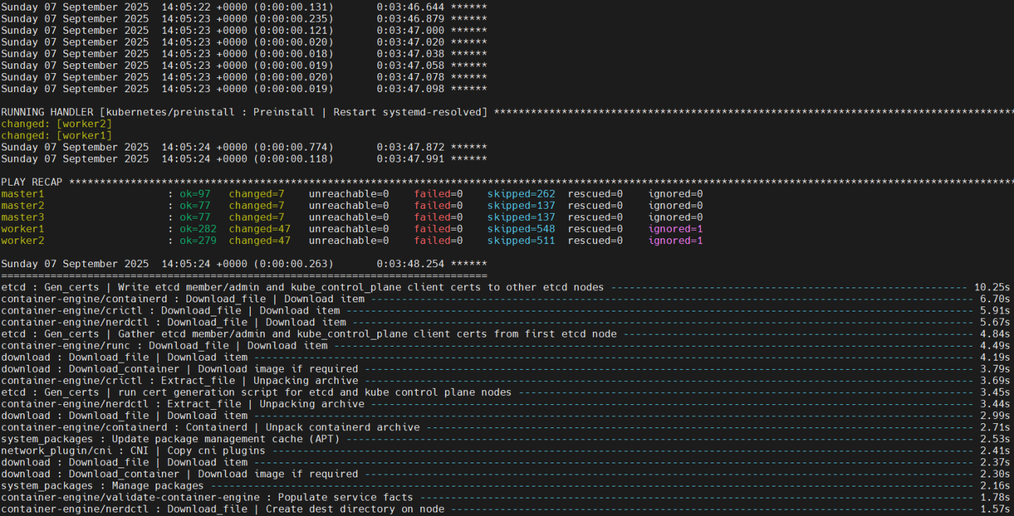
Verification
To follow the progress of the DPU provisioning, run the following command to check in which phase it currently is:
Jump Node Console
            $ watch -n10 "kubectl describe dpu -n dpf-operator-system | grep 'Node Name\|Type\|Last\|Phase'"
Every 10.0s: kubectl describe dpu -n dpf-operator-system | grep 'Node Name\|Type\|Last\|Phase'

  Dpu Node Name:                                      worker1
    Last Transition Time:  2025-09-07T14:10:24Z
    Type:                  Initialized
    Last Transition Time:  2025-09-07T14:10:24Z
    Type:                  BFBReady
    Last Transition Time:  2025-09-07T14:10:39Z
    Type:                  NodeEffectReady
    Last Transition Time:  2025-09-07T14:10:40Z
    Type:                  InterfaceInitialized
    Last Transition Time:  2025-09-07T14:10:40Z
    Type:                  FWConfigured
  Phase:  OS Installing
  Dpu Node Name:                                      worker2
    Last Transition Time:  2025-09-07T14:10:27Z
    Type:                  Initialized
    Last Transition Time:  2025-09-07T14:10:27Z
    Type:                  BFBReady
    Last Transition Time:  2025-09-07T14:10:42Z
    Type:                  NodeEffectReady
    Last Transition Time:  2025-09-07T14:10:43Z
    Type:                  InterfaceInitialized
    Last Transition Time:  2025-09-07T14:10:43Z
    Type:                  FWConfigured
  Phase:  OS Installing
Validate that the DPUs have been provisioned successfully by ensuring they're in ready state:
Jump Node Console
            $ kubectl wait --for=condition=ready --namespace dpf-operator-system dpu --all
dpu.provisioning.dpu.nvidia.com/worker1-mt2404xz0c97 condition met
dpu.provisioning.dpu.nvidia.com/worker2-mt2333xz0xvb condition met
Ensure that the following DaemonSets have 2 ready replicas:
Jump Node Console
            $ kubectl wait ds --for=jsonpath='{.status.numberReady}'=2 --namespace nvidia-network-operator kube-multus-ds sriov-network-config-daemon sriov-device-plugin
daemonset.apps/kube-multus-ds condition met
daemonset.apps/sriov-network-config-daemon condition met
daemonset.apps/sriov-device-plugin condition met

$ kubectl wait ds --for=jsonpath='{.status.numberReady}'=2 --namespace ovn-kubernetes ovn-kubernetes-node-dpu-host
daemonset.apps/ovn-kubernetes-node-dpu-host condition met
Validate that all the different DPUServices, DPUServiceIPAMs, DPUServiceInterfaces and DPUServiceChains objects are now in ready state:
Jump Node Console
            $ kubectl wait --for=condition=ApplicationsReady --namespace dpf-operator-system dpuservices -l svc.dpu.nvidia.com/owned-by-dpudeployment=dpf-operator-system_ovn-hbn
dpuservice.svc.dpu.nvidia.com/blueman-hvtnh condition met
dpuservice.svc.dpu.nvidia.com/dts-8hkcs condition met
dpuservice.svc.dpu.nvidia.com/hbn-hh6ht condition met
dpuservice.svc.dpu.nvidia.com/ovn-dfvsw condition met

$ kubectl wait --for=condition=DPUIPAMObjectReady --namespace dpf-operator-system dpuserviceipam --all
dpuserviceipam.svc.dpu.nvidia.com/loopback condition met
dpuserviceipam.svc.dpu.nvidia.com/pool1 condition met

$ kubectl wait --for=condition=ServiceInterfaceSetReady --namespace dpf-operator-system dpuserviceinterface --all
dpuserviceinterface.svc.dpu.nvidia.com/hbn-p0-if-76skb condition met
dpuserviceinterface.svc.dpu.nvidia.com/hbn-p1-if-gqlvx condition met
dpuserviceinterface.svc.dpu.nvidia.com/hbn-pf2dpu2-if-6gw7z condition met
dpuserviceinterface.svc.dpu.nvidia.com/ovn condition met
dpuserviceinterface.svc.dpu.nvidia.com/p0 condition met
dpuserviceinterface.svc.dpu.nvidia.com/p1 condition met

$ kubectl wait --for=condition=ServiceChainSetReady --namespace dpf-operator-system dpuservicechain --all
dpuservicechain.svc.dpu.nvidia.com/ovn-hbn-z9wds condition met
Congratulations, the DPF system has been successfully installed!
Infrastructure Latency & Bandwidth Validation
Verify the deployment and that you can reach link-speed performance and good latency results on the DPF system by using various tests:
- RDMA - for latency measurements
- Iperf TCP - for bandwidth measurements
Each of the tests is described thoroughly. At the end of each test, you'll see the achieved performance.
Make sure that the servers are tuned for maximum performance (not covered in this document).
The following diagram illustrates the test environment and how the network traffic is redirected via the accelerated OVN-Kubernetes and HBN services using SFC:
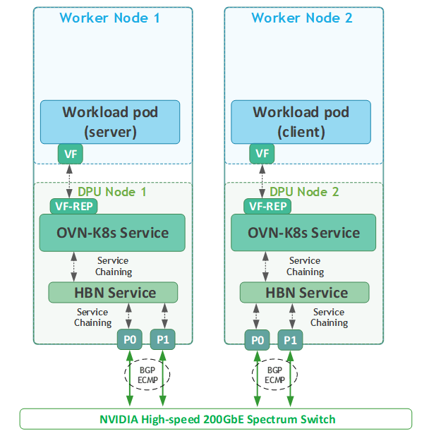
Performance Tests
RoCE Latency Test
Apply the following NetworkPolicy to enable stateless traffic:
stateless_netpolicy.yaml
apiVersion: networking.k8s.io/v1 kind: NetworkPolicy metadata: name: multi-port-egress namespace:
defaultannotations: k8s.ovn.org/acl-stateless:"true"spec: podSelector: {} policyTypes: - Egress - Ingress egress: - {} ingress: - {}Jump Node Console
$ kubectl apply -f stateless_netpolicy.yaml
Create a test Deployment using the following YAML to create 2 replicas on 2 different worker nodes:
NoteThe container image specified below must include NVIDIA user space drivers and perftest
testapp-performance-test-deployment.yaml
--- apiVersion: apps/v1 kind: Deployment metadata: name: testapp-performance labels: app: testapp-performance spec: replicas:
2selector: matchLabels: app: testapp-performance template: metadata: labels: app: testapp-performance spec: topologySpreadConstraints: - maxSkew:1topologyKey: kubernetes.io/hostname whenUnsatisfiable: DoNotSchedule labelSelector: matchLabels: app: testapp-performance containers: - name: testapp-pod image: <container_image> imagePullPolicy: Always command: ['sh','-c','trap : TERM INT; sleep infinity & wait'] securityContext: capabilities: add: ["IPC_LOCK"] resources: requests: cpu:'24'memory:'8Gi'limits: cpu:'24'memory:'8Gi'Apply the resource:
Jump Node Console
$ kubectl apply -f testapp-performance-test-deployment.yaml
Validate that the deployment is running successfully:
Jump Node Console
            $ kubectl get pods -o wide
NAME                                   READY   STATUS    RESTARTS   AGE   IP            NODE      NOMINATED NODE   READINESS GATES
testapp-performance-6cb7bd497d-4dz4j   1/1     Running   0          13m   10.233.68.3   worker2   <none>           <none>
testapp-performance-6cb7bd497d-lj2cm   1/1     Running   0          13m   10.233.67.3   worker1   <none>           <none>
Connect to one of the pods in the Deployment:
Jump Node Console
$ kubectl exec -it testapp-performance-6cb7bd497d-4dz4j -- bash
From within the container, check its IP address on its interface and see that it is recognizable as an RDMA device:
First Pod Console
            root@testapp-performance-6cb7bd497d-4dz4j:/# ip a
1: lo: <LOOPBACK,UP,LOWER_UP> mtu 65536 qdisc noqueue state UNKNOWN group default qlen 1000
    link/loopback 00:00:00:00:00:00 brd 00:00:00:00:00:00
    inet 127.0.0.1/8 scope host lo
       valid_lft forever preferred_lft forever
    inet6 ::1/128 scope host
       valid_lft forever preferred_lft forever
102: eth0: <BROADCAST,MULTICAST,UP,LOWER_UP> mtu 8940 qdisc mq state UP group default qlen 1000
    link/ether 0a:58:0a:e9:44:03 brd ff:ff:ff:ff:ff:ff permaddr 52:79:d2:fa:44:15
    altname enp137s0f0v10
    inet 10.233.68.3/24 brd 10.233.68.255 scope global eth0
       valid_lft forever preferred_lft forever
    inet6 fe80::5079:d2ff:fefa:4415/64 scope link
       valid_lft forever preferred_lft forever

root@testapp-performance-6cb7bd497d-4dz4j:/# rdma link | grep eth0
link mlx5_12/1 state ACTIVE physical_state LINK_UP netdev eth0
Start the
ib_read_latserver side:First Pod Console
            root@testapp-performance-6cb7bd497d-4dz4j:/# ib_read_lat -F -n 20000

************************************
* Waiting for client to connect... *
************************************
Using another console window , reconnect to the jump node and connect to the second pod in the deployment.
Jump Node Console
$ kubectl exec -it testapp-performance-6cb7bd497d-lj2cm -- bash
From within the container, start the
ib_read_latclient (use the IP address from the server-side container) and check the latency results:First Pod Console
            root@testapp-performance-6cb7bd497d-lj2cm:/# ib_read_lat -F -n 20000 10.233.68.3
---------------------------------------------------------------------------------------
                    RDMA_Read Latency Test
 Dual-port       : OFF          Device         : mlx5_28
 Number of qps   : 1            Transport type : IB
 Connection type : RC           Using SRQ      : OFF
 PCIe relax order: ON
 ibv_wr* API     : ON
 TX depth        : 1
 Mtu             : 4096[B]
 Link type       : Ethernet
 GID index       : 5
 Outstand reads  : 16
 rdma_cm QPs     : OFF
 Data ex. method : Ethernet
---------------------------------------------------------------------------------------
 local address: LID 0000 QPN 0x0244 PSN 0x395cf4 OUT 0x10 RKey 0x07c500 VAddr 0x0057d4910f6000
 GID: 00:00:00:00:00:00:00:00:00:00:255:255:10:233:67:03
 remote address: LID 0000 QPN 0x0234 PSN 0x523259 OUT 0x10 RKey 0x078500 VAddr 0x0059d0a3802000
 GID: 00:00:00:00:00:00:00:00:00:00:255:255:10:233:68:03
---------------------------------------------------------------------------------------
 #bytes #iterations    t_min[usec]    t_max[usec]  t_typical[usec]    t_avg[usec]    t_stdev[usec]   99% percentile[usec]   99.9% percentile[usec]
 2       20000          3.97           9.67         4.08               4.77             0.95            8.16                    8.28
---------------------------------------------------------------------------------------
iPerf TCP Bandwidth Test
Create a test Deployment using the YAML from the previous example to create a pod on each worker that you can use to test TCP connectivity and performance.
NoteThe container image specified in the test must include iperf.
Connect to one of the pods in the deployment:
Jump Node Console
$ kubectl exec -it testapp-performance-6cb7bd497d-4dz4j -- bash
Before starting the
iperf3server listeners, and to be able to achieve good results, check in another tab the cores the pod is currently running on:NoteTo be able to bind to specific cores, make sure to schedule a pod in Guaranteed QoS class.
Check on which worker node the pod is running on:
Jump Node Console
            $ kubectl get pods -o wide | grep 4dz4j
testapp-performance-6cb7bd497d-4dz4j   1/1     Running   0          18m   10.233.68.3   worker2   <none>           <none>
SSH to the worker:
Jump Node Console
            depuser@jump:~$ ssh worker2
depuser@worker2:~$ sudo -i
root@worker2:~#
Inspect the pod current cores:
Worker2 Console
            root@worker2:~# crictl ps | grep testapp
48f972357dada       138fed3c17cc0       19 minutes ago      Running             testapp-pod                   0                   7bd82b0acb59e       testapp-performance-6cb7bd497d-4dz4j
root@worker2:~# crictl inspect 48f972357dada | jq '.status.resources.linux.cpusetCpus'
Output example:
Worker2 Console
"28-51"
Back within the container of the pod, use the following script to start multiple
iperf3servers (1 for each core) on different ports:iperf_server.sh
#!/bin/bash# Cores to bind the iperf3 server processes toCORES=$1# Calculate the first_core and last_core to provide the CPU rangefirst_core=$(echo$CORES |cut-d"-"-f1) last_core=$(echo$CORES |cut-d"-"-f2)# Loop over the ports (5201 + i*2) for i in the given CPU range and run iperf3 serversforiin$(seq$first_core $last_core);doecho"Running iperf3 server on core $i"taskset -c $i iperf3 -s -p $((5201 + i * 2)) > /dev/null 2>&1 &doneStart the script using the previous CPU range (leave 1 core as a buffer):
First Pod Console
            root@testapp-performance-6cb7bd497d-4dz4j:/# chmod +x iperf_server.sh
root@testapp-performance-6cb7bd497d-4dz4j:/# ./iperf_server.sh 28-50
Running iperf3 server on core 28
Running iperf3 server on core 29

...
...
Running iperf3 server on core 49
Running iperf3 server on core 50

root@testapp-performance-6cb7bd497d-4dz4j:/# ps -ef | grep iperf3
root          39       1  0 13:02 pts/1    00:00:00 iperf3 -s -p 5257
root          40       1  0 13:02 pts/1    00:00:00 iperf3 -s -p 5259
...
...
root          60       1  0 13:02 pts/1    00:00:00 iperf3 -s -p 5299
root          61       1  0 13:02 pts/1    00:00:00 iperf3 -s -p 5301
Connect to the second pod:
Jump Node Console
$ kubectl exec -it testapp-performance-6cb7bd497d-lj2cm -- bash
- Follow the previously displayed method to identify the CPU cores the second pod is running on.
Use the following script to start multiple
iperf3clients that will connect to eachiperf3server in the first pod:NoteThe script receives 3 parameters: server IP to connect to, the cores it will spawn the
iperf3processes to, and the duration theiperf3test will run. Make sure to pass all 3 when initiating the script and providing the CPU cores as a range (28-50 in this example).jqandbcshould be installed on the pod to properly run it.
iperf_client.sh
#!/bin/bash# IP address of the server where iperf3 servers are runningSERVER_IP=$1# Change to your server's IP# Cores to bind the iperf3 client processes toCORES=$2# Duration to run the iperf3 testDUR=$3# Variable to accumulate the total bandwidth in Gbit/sectotal_bandwidth_Gbit=0# Calculate the first_core and last_core to provide the CPU rangefirst_core=$(echo$CORES |cut-d"-"-f1) last_core=$(echo$CORES |cut-d"-"-f2)# Array to store the PIDs of background taskspids=()# Loop over the ports (5201 + i*2) for i in the given CPU rangeforiin$(seq$first_core $last_core);doport=$((5201 + i * 2)) cpu_core=$i# Assign CPU core based on the value of ioutput_file="iperf3_client_results_$port.log"# Run the iperf3 client in the background with CPU core bindingtimeout $(( DUR +5 )) taskset -c $cpu_core iperf3 -c $SERVER_IP -p $port -t $DUR -J > $output_file & pid=$! pids+=("$pid")done# Wait for all background tasks to complete and check their statusforpidin"${pids[@]}";dowait $pidif[[ $? -ne0 ]];thenecho"Process with PID $pid failed or timed out."fidone# Summarize the results from each log fileecho"Summary of iperf3 client results:"foriin$(seq$first_core $last_core);doport=$((5201 + i * 2)) output_file="iperf3_client_results_$port.log"if[[ -f $output_file ]];thenecho"Results for port $port:"# Parse the results and print a summarybandwidth_bps=$(jq'.end.sum_received.bits_per_second'$output_file)if[[ -n $bandwidth_bps ]];then# Convert bandwidth from bps to Gbit/secbandwidth_Gbit=$(echo"scale=3; $bandwidth_bps / 1000000000"|bc)echo" Bandwidth: $bandwidth_Gbit Gbit/sec"# Accumulate the bandwidth for the total summarytotal_bandwidth_Gbit=$(echo"scale=3; $total_bandwidth_Gbit + $bandwidth_Gbit"|bc)# Delete current log filerm$output_fileelseecho"No bandwidth data found in $output_file"fielseecho"No results found for port $port"fidone# Print the total bandwidth summaryecho"Total Bandwidth across all streams: $total_bandwidth_Gbit Gbit/sec"Run the script and check the performance results:
Second Pod Console
            root@testapp-performance-6cb7bd497d-lj2cm:/# chmod +x iperf_client.sh
root@testapp-performance-6cb7bd497d-lj2cm:/# ./iperf_client.sh 10.233.68.3 28-50 30
Summary of iperf3 client results:
Results for port 5257:
  Bandwidth: 18.850 Gbit/sec
Results for port 5259:
  Bandwidth: 17.713 Gbit/sec
Results for port 5261:
  Bandwidth: 16.795 Gbit/sec
Results for port 5263:
  Bandwidth: 21.718 Gbit/sec
Results for port 5265:
  Bandwidth: 22.281 Gbit/sec
Results for port 5267:
  Bandwidth: 11.733 Gbit/sec
Results for port 5269:
  Bandwidth: 12.200 Gbit/sec
Results for port 5271:
  Bandwidth: 13.031 Gbit/sec
Results for port 5273:
  Bandwidth: 22.623 Gbit/sec
Results for port 5275:
  Bandwidth: 20.902 Gbit/sec
Results for port 5277:
  Bandwidth: 14.753 Gbit/sec
Results for port 5279:
  Bandwidth: 16.763 Gbit/sec
Results for port 5281:
  Bandwidth: 12.722 Gbit/sec
Results for port 5283:
  Bandwidth: 21.618 Gbit/sec
Results for port 5285:
  Bandwidth: 7.626 Gbit/sec
Results for port 5287:
  Bandwidth: 8.012 Gbit/sec
Results for port 5289:
  Bandwidth: 22.466 Gbit/sec
Results for port 5291:
  Bandwidth: 22.270 Gbit/sec
Results for port 5293:
  Bandwidth: 8.048 Gbit/sec
Results for port 5295:
  Bandwidth: 16.793 Gbit/sec
Results for port 5297:
  Bandwidth: 15.952 Gbit/sec
Results for port 5299:
  Bandwidth: 19.632 Gbit/sec
Results for port 5301:
  Bandwidth: 20.959 Gbit/sec
Total Bandwidth across all streams: 385.460 Gbit/sec
Connecting to BlueMan Web Interface
As part of the DPF system installation, DTS and Blueman DPUServices were deployed.
DOCA Telemetry Service (DTS) collects data from built-in providers (data providers such as
sysfs
,
ethtool
and
tc
, and aggregation providers such as
fluent_aggr
and
prometheus_aggr
), and from external telemetry applications.
DOCA BlueMan runs in the DPU as a standalone web dashboard and consolidates all the basic information, health, and telemetry counters into a single interface.
All the information that BlueMan provides is gathered from the DOCA Telemetry Service (DTS).
To be able to log into BlueMan and view the local DTS instance data in a convenient way, the management IP address of the DPU should be entered to a web browser located in the same network as the DPU. In this RDG, it will be demonstrated by using RDP to connect to the jump node and opening a web browser in it (same as with MaaS, Firewall).
To find out the DPU management IP address in the
10.0.110.0/24subnet, obtain the DPU names:Jump Node Console
            $ kubectl get dpus -n dpf-operator-system
NAME                   READY   PHASE   AGE
worker1-mt2404xz0c97   True    Ready   50m
worker2-mt2333xz0xvb   True    Ready   50m
Obtain the DPU management IPs (replace
worker$i-0000-89-00with your DPU name):Jump Node Console
            $ kubectl get dpus -n dpf-operator-system -o json | jq '.items[].status.addresses[0].address' | cut -d '"' -f2
10.0.110.88
10.0.110.89
In the RDP session, open a web browser and enter https://<DPU_INTERNAL_IP>. A warning of self-signed certificate should appear; click accept the risk and proceed.
Afterwards it will open the login page:
The login credentials to use are the same pair used for the SSH connection to the DPU (
ubuntu/ubuntu). However, login straight away won't work and an additional certificate exception in the browser has to be made.Open another tab in the browser and enter https://<DPU_INTERNAL_IP>:10000. It will again prompt a warning of self-signed certificate; click accept the risk to add it to your browser exception list. An error message similar to the following will be displayed, but it doesn't matter since it's an internal address to fetch resources from–in other words, the error message can be ignored.
Return to the BlueMan login page, enter the credentials, and you should be able to login.
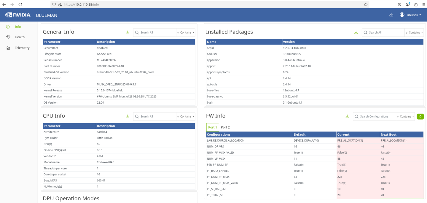
Authors

| Guy Zilberman is a solution architect at NVIDIA's Networking Solution s Labs, bringing extensive experience from several leadership roles in cloud computing. He specializes in designing and implementing solutions for cloud and containerized workloads, leveraging NVIDIA's advanced networking technologies. His work primarily focuses on open-source cloud infrastructure, with expertise in platforms such as Kubernetes (K8s) and OpenStack. |
This document is provided for information purposes only and shall not be regarded as a warranty of a certain functionality, condition, or quality of a product. NVIDIA Corporation (“NVIDIA”) makes no representations or warranties, expressed or implied, as to the accuracy or completeness of the information contained in this document and assumes no responsibility for any errors contained herein. NVIDIA shall have no liability for the consequences or use of such information or for any infringement of patents or other rights of third parties that may result from its use. This document is not a commitment to develop, release, or deliver any Material (defined below), code, or functionality. NVIDIA reserves the right to make corrections, modifications, enhancements, improvements, and any other changes to this document, at any time without notice. Customer should obtain the latest relevant information before placing orders and should verify that such information is current and complete. NVIDIA products are sold subject to the NVIDIA standard terms and conditions of sale supplied at the time of order acknowledgement, unless otherwise agreed in an individual sales agreement signed by authorized representatives of NVIDIA and customer (“Terms of Sale”). NVIDIA hereby expressly objects to applying any customer general terms and conditions with regards to the purchase of the NVIDIA product referenced in this document. No contractual obligations are formed either directly or indirectly by this document.