RDG for NVIDIA network Accelerated VMware vSphere with Tanzu Cluster
Created on Jan 16, 2022
Updated on May 24, 2022
Introduction
The following Reference Deployment Guide (RDG) explains how to install and configure VMware vSphere Tanzu version 7.0 Update 3d with NSX-Data Center 3.2 version on a single vSphere cluster over NVIDIA® accelerated end-to-end 25/100 Gbps Ethernet solution. This setup is capable of running RDMA and DPDK-based applications. VMware’s vSAN over RDMA will be used as a share storage for the vSphere Tanzu Workloads.
Abbreviations and Acronyms
|
Term |
Definition |
Term |
Definition |
|
DAC |
Direct Attached Cable |
RDMA |
Remote Direct Memory Access |
|
DHCP |
Dynamic Host Configuration Protocol |
RoCE |
RDMA over Converged Ethernet |
|
DPDK |
Data Plane Development Kit |
SDS |
Software-Defined Storage |
|
CNI |
Container Network Interface |
VDS |
vSphere Distributed Switch |
|
NOS |
Network Operation System |
VM |
Virtual Machine |
Introduction
Provisioning Tanzu Kubernetes cluster for running RDMA and DPDK-based workloads may become an extremely complicated task. Proper design, and software and hardware component selection may become a gating task toward successful deployment.
This guide provides a step-by-step instructions to deploy vSphere with Tanzu with combined Management, Edge and Workload functions on a single vSphere cluster including technology overview, design, component selection, and deployment steps.
vSphere with Tanzu requires specific networking configuration to enable connectivity to the Supervisor Clusters , vSphere Namespaces , and all objects that run inside the namespaces, such as vSphere Pods , VMs, and Tanzu Kubernetes clusters. We are going to configure the networking manually by deploying a new instance of NSX-T Data Center and vSphere VDS .
VMware’s vSANoRDMA is now fully qualified and available as of the ESXi 7.0 U2 release, making it ready for deployments.
In this document, we will be using the NVIDIA Network Operator which is in responsible for deploying and configuring with a Host Device Network mode. This allow to run RDMA and DPDK workloads on a Tanzu Kubernetes Cluster Worker Node.
References
Solution Architecture
Key Components and Technologies
NVIDIA Spectrum Ethernet Switches
Flexible form-factors with 16 to 128 physical ports, supporting 1GbE through 400GbE speeds.
Based on a ground-breaking silicon technology optimized for performance and scalability, NVIDIA Spectrum switches are ideal for building high-performance, cost-effective, and efficient Cloud Data Center Networks, Ethernet Storage Fabric, and Deep Learning Interconnects.
NVIDIA combines the benefits of NVIDIA Spectrum™ switches, based on an industry-leading application-specific integrated circuit (ASIC) technology, with a wide variety of modern network operating system choices, including NVIDIA Cumulus® Linux , SONiC and NVIDIA Onyx®.
NVIDIA® Cumulus® Linux is the industry's most innovative open network operating system that allows you to automate, customize, and scale your data center network like no other.
NVIDIA ConnectX SmartNICs
10/25/40/50/100/200 and 400G Ethernet Network Adapters
The industry-leading NVIDIA® ConnectX® family of smart network interface cards (SmartNICs) offer advanced hardware offloads and accelerations.
NVIDIA Ethernet adapters enable the highest ROI and lowest Total Cost of Ownership for hyperscale, public and private clouds, storage, machine learning, AI, big data, and telco platforms.
The NVIDIA® LinkX® product family of cables and transceivers provides the industry’s most complete line of 10, 25, 40, 50, 100, 200, and 400GbE in Ethernet and 100, 200 and 400Gb/s InfiniBand products for Cloud, HPC, hyperscale, Enterprise, telco, storage and artificial intelligence, data center applications.
- Run Kubernetes workloads using your existing IT infrastructure. vSphere with Tanzu bridges the gap between IT and developers for cloud-native apps on-premises and in the cloud.
VMware vSphere Distributed Switch (VDS) provides a centralized interface from which you can configure, monitor and administer virtual machine access switching for the entire data center. The VDS provides simplified Virtual Machine network configuration, enhanced network monitoring and troubleshooting capabilities.
VMware NSX-T Data Center provides an agile software-defined infrastructure to build cloud-native application environments.
NSX-T Data Center focuses on providing networking, security, automation, and operational simplicity for emerging application frameworks and architectures that have heterogeneous endpoint environments and technology stacks. NSX-T Data Center supports cloud-native applications, bare metal workloads, multi-hypervisor environments, public clouds, and multiple clouds.
NSX-T Data Center is designed for management, operation, and consumption by development organizations. NSX-T Data Center allows IT teams and development teams to select the technologies best suited for their applications.
vSAN over RoCE Support for VMware (vSAN RDMA) provides increased performance for vSAN.
RDMA (Remote Direct Memory Access) is an innovative technology that boosts data communication performance and efficiency. RDMA makes data transfers more efficient and enables fast data movement between servers and storage without using the OS or burdening the server’s CPU. Throughput is increased, latency reduced and the CPU is freed to run applications.
RDMA over Converged Ethernet ( RoCE ) or InfiniBand over Ethernet ( IBoE ) [1] is a network protocol that allows remote direct memory access (RDMA) over an Ethernet network. It does this by encapsulating an InfiniBand (IB) transport packet over Ethernet.
NVIDIA Network Operator leverages Kubernetes CRDs and Operator SDK to manage networking related components, in order to enable fast networking, RDMA and GPUDirect for workloads in a Kubernetes cluster.
Logical Design
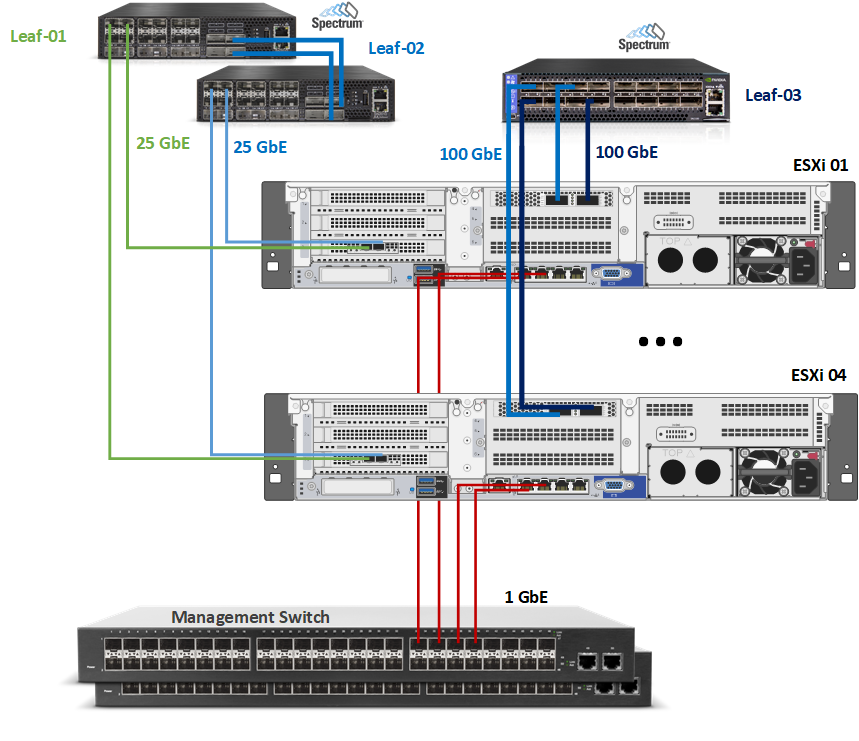
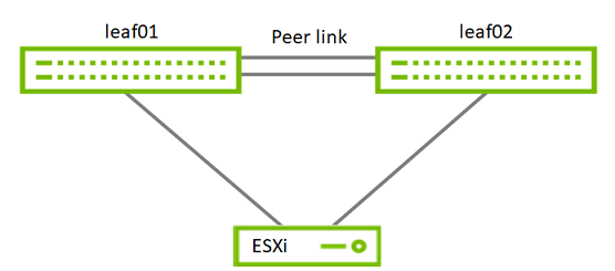
The setup used one vSphere cluster that includes 4 ESXi servers connected to two NVIDIA® Spectrum® SN2010 Ethernet switches (Management, Ingress and Egress traffic) and one NVIDIA® Spectrum® 2 SN3700 Ethernet switch (High speed vSAN, RDMA and DPDK traffic).
vCenter and NSX-T Managers VM will be placed on the same cluster.
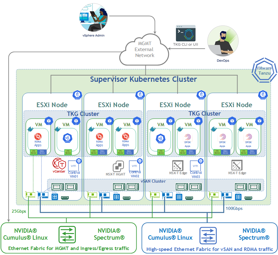
For production design, we recommend to place a vCenter and an NSX-T Managers in a separate management cluster. This is recommended for VMware Validated Design (VVD) and VMware Cloud Foundation (VCF) which is based on VVD.
Network Design
vSphere Tanzu Networks
vSphere with Tanzu requires specific networking configuration to enable connectivity to the Supervisor Clusters , vSphere Namespaces , and all objects that run inside the namespaces, such as vSphere Pods , VMs, and Tanzu Kubernetes clusters.
We are going to configure the Supervisor Cluster networking manually by deploying a new instance of NSX-T Data Center .
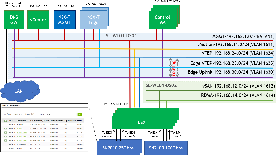
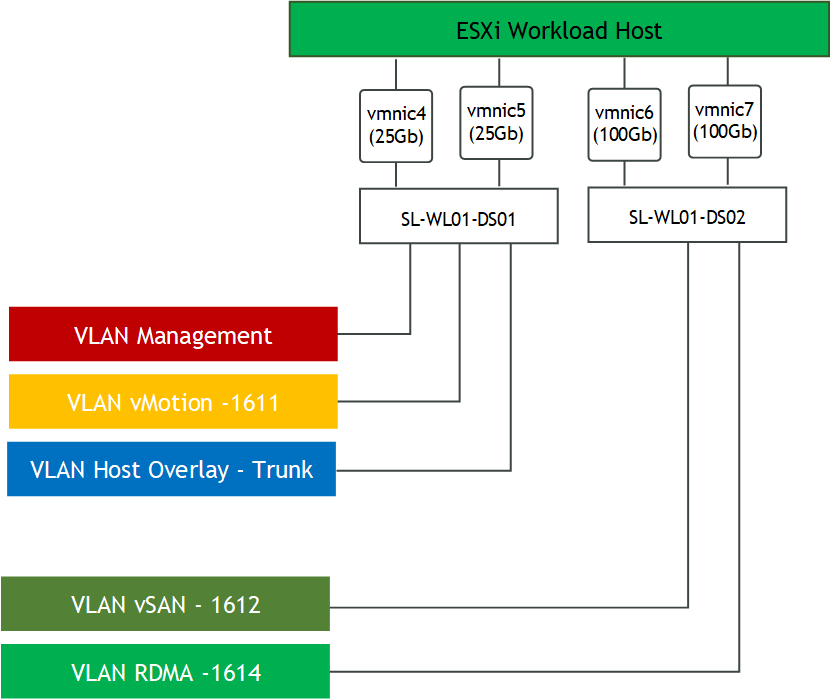
SL-WL01-DS-01 VDS:
Management Network (VLAN 1 - 192.168.1.x/24)
This is where the ESXi VMkernel interface and Management VMs will reside such as the NSX-T Manager and vCenter.
WarningDHCP and DNS services are required. The components installation and configuration are not covered in this guide.
vMotion Network (VLAN 1611 – 192.168.11.0/24)
This is where the ESXi vMotion VMkernel interfaces will reside.NSX-T Geneve Overlay Network for ESXi Hosts (VLAN 1624 - 192.168.24.0/24) – This network will be used by the Geneve Overlay Tunnel endpoints VMkernel interfaces on the ESXi Hosts.
NSX-T Geneve Overlay Network for Edge VMs (VLAN 1625 - 192.168.25.0/24) – This network will be used by the Geneve Overlay Tunnel endpoints VMkernel interfaces on the Edge VMs.
NSX-T Edge VMs Uplink Network (VLAN 1630 -192.168.25.0/24) – This network will be used by
SL-WL01-DS-02 VDS:
vSAN Network (VLAN 1612 – 192.168.12.0/24)
This is where the ESXi vSAN VMkernel interfaces will reside.RDMA Network (VLAN 1614 – 192.168.14.0/24)
This is where the ESXi vSAN VMkernel interfaces will reside.
Internet Network – The environment can access the Internet including the TKG Clusters.
Supervisor Cluster Networking
Workload Management which will be realized in NSX-T.
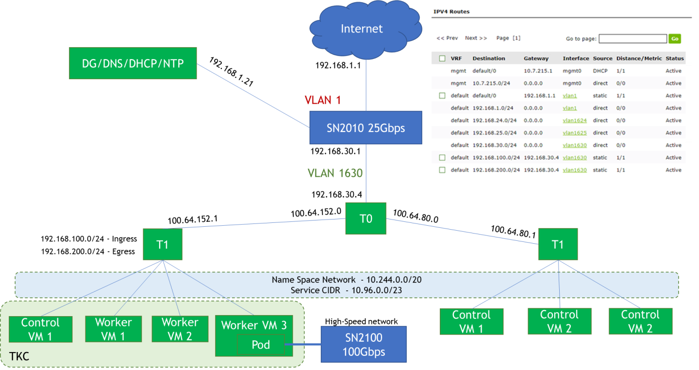
Pod CIDR (Default – 10.244.0.0/20) – This network is used for the Kubernetes Pods. It will be further segment into /28 segments per namespace or per TKG cluster. This is an internal address pool which does not need to be routed from the physical router.
Services CIDR (Default 10.96.0.0/23) – This network pool will be used when you create a Kubernetes service. This is an internal address pool which does not need to be routed from the physical router.
Ingress CIDR (192.168.100.0/24) – This network pool will provide addresses for when load-balancing services are required as part of an application deployment. For example, one NSX-T Load Balancer VIP will be assigned to the Control Plane IP Address for the Supervisor Cluster.
Egress CIDR (192.168.200.0/24) – This network pool will be used when the Pods require to communicate outside the NSX-T environment, such as accessing to the Internet. For example, one IP will be assigned to the T0 router as a source NAT(SNAT) source address when the Pods access the Internet.
WarningBoth the Ingress and Egress CIDR networks need to be routed on the physical router next-hop to the T0.
Software Stack Components
This guide assumes the following software and drivers are installed:
VMware ESXi 7.0.3, build 17630552
VMware vCenter 7.0.3, build 17694817
Distributed Switch 7.0.3
NSX-T 3.2
NVIDIA® ConnectX® Driver for VMware ESXi Server v4.21.71.101
NVIDIA® ConnectX®-6DX FW version 22.32.2004
NVIDIA® ConnectX®-6LX FW version 26.32.1010
Network Operational System (NOS): NVIDIA Cumulus™ v 5.1
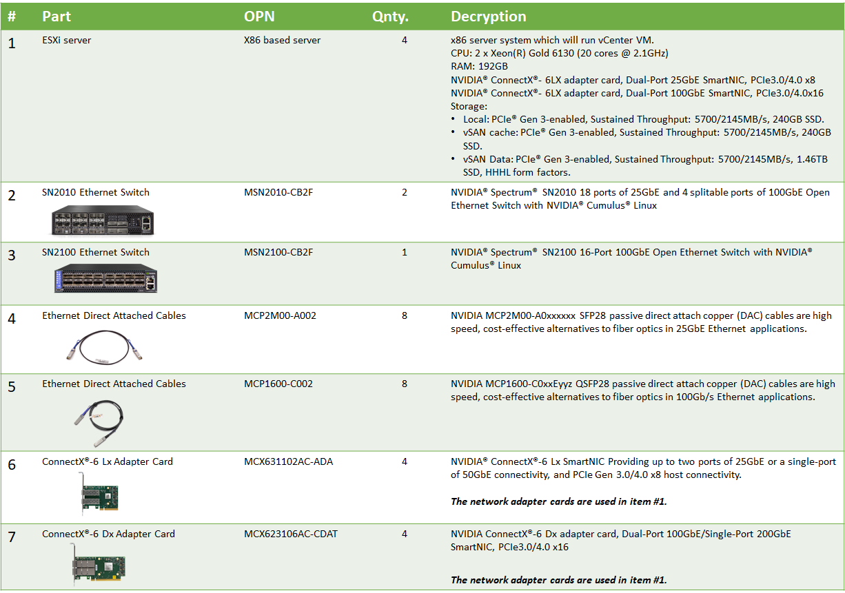
Bill of Materials
The following hardware setup is utilized in the vSphere environment described in this guide.
Supervisor Cluster Hardware:
Supervisor Cluster Compute/Storage:
|
VM |
CPU |
MEM |
DISK |
|
Compute Cluster vCenter (based on Small) |
4 |
20GB |
48GB |
|
NSX-T Manager x 3 |
6 |
24GB |
300GB |
|
NSX-T Edge VMs (minimum Large) x 2 |
8 |
32GB |
200GB |
|
Supervisor Cluster VMs (based on Tiny) |
2 |
8GB |
22GB |
|
Guest Clusters (based on x-small) x 3 |
2 |
2GB |
16GB |
Deployment and Configuration
Installing ESXi, vCenter, ESXi hosts vCenter, configuring virtual DCs, clusters, virtual Data Center, vSphere cluster and adding ESXi hosts and hosts to clusters is outside of the scope of the document.
Wiring
This document covers highly available VMware vSphere cluster deployment.
Supervisor Cluster:
vSphere Distributed Switches Design
Network
Prerequisites
Switch OS
NVIDIA® Cumulus® Linux v5.1Network adapter
NVIDIA ConnectX-6 Lx and ConnectX-6 Dx adapter cards.
Latest FW and Driver versions. For more information, please see:vSAN over RDMA
vSAN RDMA Ready network adapter is required and can be found on the vSAN VCG.Management Network
DHCP and DNS services are required.
WarningThe components installation and configuration are not covered in this guide.
Hosts Network Configuration
This table provides details of the ESXi server, switches names and their network configuration.
SL-WL01-Cluster01 Supervisor Cluster
|
Server |
Server Name |
IP and NICs |
|
|
High-Speed Ethernet Network |
Management Network 192.168.1.0/24 |
||
|
ESXi-01 |
clx-host-51 |
vmk1: 192.168.11.111 (vMotion) vmk2: 192.168.12.111 (vSAN) vmk10: From IP Pool 192.168.24.0/24 (NSX Host TEP) |
vmk0: 192.168.1.111 From DHCP (reserved) |
|
ESXi-02 |
clx-host-52 |
vmk1: 192.168.11.112 (vMotion) vmk2: 192.168.12.112 (vSAN) vmk10: From IP Pool 192.168.24.0/24 (NSX Host TEP) |
vmk0: 192.168.1.11 2 From DHCP (reserved) |
|
ESXi-03 |
clx-host-53 |
vmk1: 192.168.11.113(vMotion) vmk2: 192.168.12.113 (vSAN) vmk10: From IP Pool 192.168.24.0/24 (NSX Host TEP) |
vmk0: 192.168.1.11 3 From DHCP (reserved) |
|
ESXi-04 |
clx-host-54 |
vmk1: 192.168.11.114(vMotion) vmk2: 192.168.12.114 (vSAN) vmk10: From IP Pool 192.168.24.0/24 (NSX Host TEP) |
vmk0: 192.168.1.11 4 From DHCP (reserved) |
|
Leaf-01 |
clx-swx-033 |
10.7.215.233 |
|
|
Leaf-02 |
clx-swx-034 |
10.7.215.234 |
|
|
Leaf-03 |
clx-swx-035 |
10.7.215.235 |
|
|
vCenter (VM) |
sl01w01vc01 |
192.168.1.25 |
|
|
NSX-T Manager 01 (VM) |
sl01w01nsx01 |
192.168.1.26 |
|
|
NSX-T Edge 01 (VM) |
sl01w01nsxedge01 |
From IP Pool 192.168.25.0/24 (NSX Edge TEP) |
192.168.1.28 |
|
NSX-T Edge 02 (VM) |
sl01w01nsxedge02 |
From IP Pool 192.168.25.0/24 (NSX Edge TEP) |
192.168.1.29 |
|
NSX-T Edge Cluster |
EdgeCluster1 |
||
|
FreeNAS ISCSI Storage (VM) |
sl01w01fnas01 |
192.168.1.27 |
|
|
DNS/DHCP/AD/NTP/Bridge VM |
10.7.215.24 |
192.168.1.21 |
|
Network Switch Configuration
ESXi to Leaf's connection
Port Channel and VLAN Configuration
Run the following commands on both Leaf NVIDIA SN2010 switches in the Supervisor Cluster to configure port channel and VLAN .
Sample for clx-swx-033 switch:
Switch console
            cumulus@clx-swx-033:mgmt:~$sudo nv set system hostname clx-swx-033
cumulus@clx-swx-033:mgmt:~$sudo nv set interface lo ip address 10.10.10.1/32
cumulus@clx-swx-033:mgmt:~$sudo nv set interface swp1-22 type swp
cumulus@clx-swx-033:mgmt:~$sudo nv set interface swp7 link speed 1G
cumulus@clx-swx-033:mgmt:~$sudo nv set interface swp7 link mtu 1500
cumulus@clx-swx-033:mgmt:~$sudo nv set interface swp1-4 bridge domain br_default
cumulus@clx-swx-033:mgmt:~$sudo nv set interface swp7 bridge domain br_default
cumulus@clx-swx-033:mgmt:~$sudo nv set bridge domain br_default vlan 1611
cumulus@clx-swx-033:mgmt:~$sudo nv set bridge domain br_default vlan 1624-1625
cumulus@clx-swx-033:mgmt:~$sudo nv set bridge domain br_default vlan 1630
cumulus@clx-swx-033:mgmt:~$sudo nv set interface vlan1 ip address 192.168.1.254/24
cumulus@clx-swx-033:mgmt:~$sudo nv set interface vlan1624 ip address 192.168.24.1/24
cumulus@clx-swx-033:mgmt:~$sudo nv set interface vlan1625 ip address 192.168.25.1/24
cumulus@clx-swx-033:mgmt:~$sudo nv set interface vlan1630 ip address 192.168.30.1/24
cumulus@clx-swx-033:mgmt:~$sudo nv set interface vlan1 link mtu 1500
cumulus@clx-swx-033:mgmt:~$sudo nv set vrf default router static 0.0.0.0/0 via 192.168.1.21
cumulus@clx-swx-033:mgmt:~$sudo nv set vrf default router static 192.168.100.0/24 via 192.168.30.4
cumulus@clx-swx-033:mgmt:~$sudo nv set vrf default router static 192.168.200.0/24 via 192.168.30.4
cumulus@clx-swx-033:mgmt:~$sudo nv set interface peerlink bond member swp21-22
cumulus@clx-swx-033:mgmt:~$sudo nv set mlag mac-address 44:38:39:BE:EF:AA
cumulus@clx-swx-033:mgmt:~$sudo nv set mlag backup 10.10.10.2
cumulus@clx-swx-033:mgmt:~$sudo nv set mlag peer-ip linklocal
cumulus@clx-swx-033:mgmt:~$sudo nv config apply
cumulus@clx-swx-033:mgmt:~$sudo nv config save
Sample for clx-swx-034 switch:
Switch console
            cumulus@clx-swx-033:mgmt:~$sudo nv set system hostname clx-swx-034
cumulus@clx-swx-033:mgmt:~$sudo nv set interface lo ip address 10.10.10.2/32
cumulus@clx-swx-033:mgmt:~$sudo nv set interface swp1-22 type swp
cumulus@clx-swx-033:mgmt:~$sudo nv set interface swp1-4 bridge domain br_default
cumulus@clx-swx-033:mgmt:~$sudo nv set bridge domain br_default vlan 1611
cumulus@clx-swx-033:mgmt:~$sudo nv set bridge domain br_default vlan 1624-1625
cumulus@clx-swx-033:mgmt:~$sudo nv set bridge domain br_default vlan 1630
cumulus@clx-swx-033:mgmt:~$sudo nv set interface vlan1 ip address 192.168.1.254/24
cumulus@clx-swx-033:mgmt:~$sudo nv set interface vlan1624 ip address 192.168.24.1/24
cumulus@clx-swx-033:mgmt:~$sudo nv set interface vlan1625 ip address 192.168.25.1/24
cumulus@clx-swx-033:mgmt:~$sudo nv set interface vlan1630 ip address 192.168.30.1/24
cumulus@clx-swx-033:mgmt:~$sudo nv set interface vlan1 link mtu 1500
cumulus@clx-swx-033:mgmt:~$sudo nv set vrf default router static 0.0.0.0/0 via 192.168.1.21
cumulus@clx-swx-033:mgmt:~$sudo nv set vrf default router static 192.168.100.0/24 via 192.168.30.4
cumulus@clx-swx-033:mgmt:~$sudo nv set vrf default router static 192.168.200.0/24 via 192.168.30.4
cumulus@clx-swx-033:mgmt:~$sudo nv set interface peerlink bond member swp21-22
cumulus@clx-swx-033:mgmt:~$sudo nv set mlag mac-address 44:38:39:BE:EF:AA
cumulus@clx-swx-033:mgmt:~$sudo nv set mlag backup 10.10.10.1
cumulus@clx-swx-033:mgmt:~$sudo nv set mlag peer-ip linklocal
cumulus@clx-swx-033:mgmt:~$sudo nv config apply
cumulus@clx-swx-033:mgmt:~$sudo nv config save
Port Channel and VLAN Configuration on a High Speed NVIDIA SN2100 Switches
Run the following commands on the High Speed switch in the vSphere Cluster to configure port channel and VLAN .
Sample for the clx-swx-035:
Switch console
            cumulus@clx-swx-035:mgmt:~$sudo nv set interface swp9-16 link mtu 1500
cumulus@clx-swx-035:mgmt:~$sudo nv set interface swp1-16 bridge domain br_default
cumulus@clx-swx-035:mgmt:~$sudo nv set bridge domain br_default vlan 1612
cumulus@clx-swx-035:mgmt:~$sudo nv set bridge domain br_default vlan 1614
cumulus@clx-swx-035:mgmt:~$sudo set interface swp1-16 bridge domain br_default untagged 1614
cumulus@clx-swx-035:mgmt:~$sudo nv config apply
cumulus@clx-swx-035:mgmt:~$sudo nv config save
Enable RDMA over Converged Ethernet Lossless (with PFC and ETS) on High Speed SN2100 Switch
RoCE transport is utilized to accelerate vSAN networking. To get the highest possible results, the network is configured to be lossless.
Run the following commands on all Leaf switches to configure a lossless networks for NVIDIA Cumulus.
Switch console
            cumulus@clx-swx-035:mgmt:~$sudo nv set qos roce
cumulus@clx-swx-035:mgmt:~$sudo nv config apply
cumulus@clx-swx-035:mgmt:~$sudo nv config save
To check RoCE configuration, run the following command:
Switch console
            cumulus@leaf-01:mgmt:~$sudo nv show qos roce

                    operational  applied   description
------------------  -----------  --------  ------------------------------------------------------
enable                           on        Turn the feature 'on' or 'off'.  The default is 'off'.
mode                lossless     lossless  Roce Mode
cable-length        100          100       Cable Length(in meters) for Roce Lossless Config
congestion-control
  congestion-mode   ECN                    Congestion config mode
  enabled-tc        0,3                    Congestion config enabled Traffic Class
  max-threshold     1.43 MB                Congestion config max-threshold
  min-threshold     146.48 KB              Congestion config min-threshold
pfc
  pfc-priority      3                      switch-prio on which PFC is enabled
  rx-enabled        enabled                PFC Rx Enabled status
  tx-enabled        enabled                PFC Tx Enabled status
trust
  trust-mode        pcp,dscp               Trust Setting on the port for packet classification


RoCE PCP/DSCP->SP mapping configurations
===========================================
        pcp  dscp                     switch-prio
    --  ---  -----------------------  -----------
    0   0    0,1,2,3,4,5,6,7          0
    1   1    8,9,10,11,12,13,14,15    1
    2   2    16,17,18,19,20,21,22,23  2
    3   3    24,25,26,27,28,29,30,31  3
    4   4    32,33,34,35,36,37,38,39  4
    5   5    40,41,42,43,44,45,46,47  5
    6   6    48,49,50,51,52,53,54,55  6
    7   7    56,57,58,59,60,61,62,63  7


RoCE SP->TC mapping and ETS configurations
=============================================
        switch-prio  traffic-class  scheduler-weight
    --  -----------  -------------  ----------------
    0   0            0              DWRR-50%
    1   1            0              DWRR-50%
    2   2            0              DWRR-50%
    3   3            3              DWRR-50%
    4   4            0              DWRR-50%
    5   5            0              DWRR-50%
    6   6            6              strict-priority
    7   7            0              DWRR-50%


RoCE pool config
===================
        name                   mode     size   switch-priorities  traffic-class
    --  ---------------------  -------  -----  -----------------  -------------
    0   lossy-default-ingress  Dynamic  50.0%  0,1,2,4,5,6,7      -
    1   roce-reserved-ingress  Dynamic  50.0%  3                  -
    2   lossy-default-egress   Dynamic  50.0%  -                  0,6
    3   roce-reserved-egress   Dynamic  inf    -                  3


Exception List
=================
        description
Supervisor Cluster Configuration
Prerequisites
Host BIOS
Verify that an SR-IOV supported server platform is being used and review the BIOS settings in the server platform vendor documentation to enable SR-IOV in the BIOS.
Physical server configuration
All ESXi servers must have the same PCIe placement for the NIC and expose the same interface name.
Experience with Kubernetes
Familiarization with the Kubernetes Cluster architecture is essential.
Verify that your environment meets the system requirements for configuring a vSphere cluster as a Supervisor Cluster. For information about requirements, see System Requirements for Setting Up vSphere with Tanzu with NSX-T Data Center.
Assign the VMware vSphere 7 Enterprise Plus with an Add-on for Kubernetes license to all ESXi hosts that will be part of the Supervisor Cluster.
Verify that you have the Modify cluster-wide configuration privilege on the cluster.
Verify that in your environment NTP configured and works properly.


Create and configure 2 VMware VDS by using following document - How-to: Configure a vSphere Distributed Switch with NVIDIA network fabric.
Two VDS will be used in the environment:
SL-WL01-DS01 with following port groups:
SL-WL01-MGMT-VLAN1
SL-WL01-vMotion-VLAN611
SL-WL01-Trunk-PG
SL-WL01-DS02 with following port groups:
SL-WL01-vSAN-VLAN1612
SL-WL01-RDMA-VLAN1614
Create and configure a VMware vSAN RDMA cluster by using following document - RDG: VMware vSAN over RoCE on VMware vSphere 7.0 U3.
WarningAs one of prerequisites for Supervisor Cluster configuration, you need to Create the VM Storage Policies. We will use in our case the vSAN Storage Police.
Enable DRS and HA on the SL-WL01-Cluster01 vSphere Cluster.


Enable SR-IOV.
NVIDIA Network Operator leverages Kubernetes CRDs and Operator SDK to manage networking-related components to enable fast networking and RDMA for workloads in TKG cluster. The fast network is a secondary network of the K8s cluster for applications that require high bandwidth or low latency.
In Tanzu Kubernetes Cluster we can use Dynamic DirectPath I/O to assign multiple PCI passthrough or SR-IOV devices to a Kubernetes Workload VM.To make it work, we need to enable SR-IOV capability on a ConnectX-6 Dx network adapter.
To Enable SR-IOV:Launch the vSphere Web Client and connect to a vCenter Server instance.
Navigate to a ESXi host and select Configure → Hardware → PCI Devices. Click on ALL PCI DEVICES. Click on Filter.

Type Mellanox and click on Vendor Name.

Select a ConnectX-6 Dx NIC.

Click on CONFIGURE SR-IOV.

Enable SR-IOV and set the number of Virtual functions (VF).
Click OK.

Click on PASSTHROUGH-ENABLED DEVICES to verify that 8 VFs were enabled.

Enable Content Library.
To enable Content Library:
Launch the vSphere Web Client and connect to a vCenter Server instance.
Navigate to vCenter → Menu → Content Libraries.

Click CREATE.
Fill Name → Tanzu.
Click NEXT.

Select Subscribed content library. Fil the Subscription URL → https://wp-content.vmware.com/v2/latest/lib.json.
Click NEXT.

Click YES.

Click NEXT.

Select the storage where you want to store the ova images → datastore01-ISCSI .
Click NEXT.

Click FINISH.

This is how it looks like when the image is downloaded successfully.

Install and configure a VMware NSX-T Data Center for vSphere following document - How-to: Install and Configure an NSX-T with NVIDIA network fabric.
Create the Segment required for Tier-0 Uplinks.
To create the Segment:
Log in to NSX manager UI login page by using the URL "https://<fqdn or IP>".
Navigate to Networking → Segments.
Click ADD Segment.

Fill up the Segment Name, Transport Zone, Subnets and VLAN.
Click SAVE.

Click NO.

The Segment was created.

Configure the Tier-0 Gateway.
To configure the Tier-0 Gateway:
Log in to NSX manager UI login page by using the URL "https://<fqdn or IP>".
Navigate to Networking → Tier-0 Gateways.
Click DD Gateway and choose Tier-0.

Fill up the Tier-0 Gateway Name → T0-EdgeCluster1 . Select HA Mode → Active Standby(in our case, you can select Active Active) , Fail Over → Preemptive, Edge Cluster → EdgeCluster1 and Preferred Edge → sl01wl01nsxedge01.
Click SAVE.

Select Yes when asked if you wish to continue to configure this Tier-0 Gateway.

Click Set under Interfaces.

Click Add Interface.
Define Name → T0-Uplink1-Int, Type → External, IP Address/Mask → 192.168.30.5/24, Connect To(Segment) → Seg-T0-Uplink1,Edge Node → sl01wl01nsxedge01 .Click SAVE.

Click Add Interface for the 2nd Edge VM.
Define Name → T0-Uplink2-Int, Type → External, IP Address/Mask → 192.168.30.6/24, Connect To(Segment) → Seg-T0-Uplink1,Edge Node → sl01wl01nsxedge02 .Click SAVE.

The following shows that both interfaces for the Tier-0 Gateway are created correctly.

Click Set under HA VIP Configuration.

Click ADD HA VIP CONFIGURATION. Fill IP Address / Mask → 192.168.30.4/24, Interface → T0-Uplink1-Int1, T0-Uplink1-Int2.
Click ADD.

The following shows that the HA VIP configuration has been successfully created.
To ensure that the Tier-0 Gateway Uplink is configured correctly, we shall login to the next hop device, in my case is the SN2010, to do a ping test.
Firstly ping yourself ie. 192.168.30.1 which is configured on the switch then follow be the HA VIP configured on the Tier-0 Gateway.
Lastly we need to configured a default route out so that the containers can communicate back to IP addresses outside the NSX-T domain.
Click Set under Static Routes in the Routing option.WarningIf you are using BGP, then probably this step would differ.

Click ADD STATIC ROUTE. Fill Name → Default, Network → 0.0.0.0/0.
Click Set under the Next Hops option.

Click SET NEXT HOP. IP Address → 192.168.30.1.
Click ADD.

Click SAVE.

Click CLOSE.

Click SAVE.

Once the static route has been added, one way is to test is from outside the NSX-T domain. In our case, we have the DG VM which is outside the NSX-T domain and the gateway of the VM is pointing to the SN2010 as well. A ping test was done from the VM to the Tier-0 Gateway VIP. If the ping test is successful, it means the static route we added to the Tier-0 gateway is successfully configured.

Validate whether NSX-T has been successfully set up for vSphere with Kubernetes.
As all the configuration on the NSX-T, vSphere VDS and physical network are set up, now go back to Workload Management to see whether we are ready to deploy Workload Management Clusters.
Enabling Workload Management and Creating a Supervisor Cluster.
To enable Workload Management and create a Supervisor Cluster:
Launch the vSphere Web Client and connect to a vCenter Server instance.
Navigate to vCenter → Menu → Workload Management .
Click GET STARTED.

Select NSX under Select a networking stack.

Select vSphere cluster → Sl-WL01-Cluster01.
Click NEXT.

Select a storage police → vSAN Default Storage Policy.
Click NEXT.

Configure Management Network. Network Mode → DHCP, Network → SL-WL01-MGMT-VLAN1.
Click NEXT.
ImportantNTP is very important. Thus, when you see authentication errors in the wcpsvc logs, usually this has to do with NTP not working correctly.

Configure Workload Network.
vSphere Distributed Switch → SL-WL01-DS01, Edge Cluster → EdgeCluster1, DNS Server(s) → 192.168.1.21, Tier-0 Gateway → T0-EdgeCluster1,NAT Mode → Enabled (Default) ,Subnet Prefix → /28 (Default), Namespace Network → 10.244.0.0./20 (Default), Service CIDR → 10.96.0.0./23 (Default), Ingress CIDRs → 192.168.100.0/24, Egress CIDRs → 192.168.200.0/24.Click NEXT.

Click Add to select the Content Library.

Select Tanzu content library.
Click OK.

Click NEXT.

Click FINISH.

The Supervisor Cluster Control VMs is being deployed.
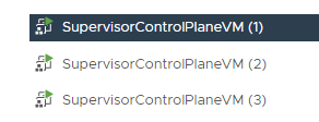
Come back in about 25 mins and see the Supervisor Cluster being deployed.

You can view the Network configuration here.

Create New VM Class
To create New VM Class included second high speed network:
Launch the vSphere Web Client and connect to a vCenter Server instance.
Navigate to vCenter → Menu → Workload Management → Services .
Click GOT IT.
Click CREATE VM CLASS .
Fill following data:VM Class Name → best-effort-2xlarge-pci vCPU Count → 8 Memory → 64 GB Add Advanced Configuration → Select PCI Device.Click NEXT.

Click ADD PCI DEVICE and s elect Dynamic DirectPath IO.

Select ConnectX Family nmlx5Gen Virtual Function. And click NEXT and FINISH in case you don't want to add another PCI Devices.

Click FINISH.

Create Namespace, Set up Permissions, Storage, Add Content Library and VM Classes
To createa Namespace:
Launch the vSphere Web Client and connect to a vCenter Server instance.
Navigate to vCenter → Menu → Workload Management .
Click on the Namespaces tab .

Click CREATE NAMESPACE.

Select Cluster → SL-WL01-Cluster01 where you want to create the namespace and give a Name → sl-wl01-ns01 to the namespace.
Click CREATE.

The namespace has been created successfully.
Click ADD PERMISSIONS.

Give permissions to Administrator@vsphere.local with edit role.
Click ADD STORAGE to add a storage to the Namespace.

Add Storage Policies → vSAN Default Storage Policy .

Click ADD CONTENT LIBRARY to add a Content Library.

Select the Tanzu Content Library.
Click OK.
Click ADD VM CLASS to add VM CLASSES.

Select the best-effort-2xlarge-pci VM class created before. We are going to use the VM class as a TKC Worker VM template as we need a second high speed network.
In additional select the best-effort-small. We are going to use the VM class as a TKC control VM template.

This is how it looks like.

Download and Install the Kubernetes CLI Tools for vSphere
You can use Kubernetes CLI tools for vSphere to view and control vSphere with Tanzu namespaces and clusters.
The Kubernetes CLI tools download package includes two executables: the standard open-source kubectl and the vSphere Plugin for kubectl.
Launch the vSphere Web Client and connect to a vCenter Server instance.
Navigate to vCenter → Menu → Workload Management . Select the Namespace ns-01.
Select the Summary tab and locate the Status area on this page.
Select Open underneath the Link to CLI Tools heading to open the download page.

Using a browser, navigate to the Kubernetes CLI Tools download URL for your environment. Referee to the prerequisites section above for guidance on how to locate the download URL.

To verify the installation of the kubectl CLI, start a shell, terminal, or command prompt session and run the command kubectl.
You see the kubectl banner message, and the list of command-line options for the CLI.
To verify the installation of the vSphere Plugin for kubectl, run the command kubectl vsphere.
You see the vSphere Plugin for kubectl banner message, and the list of command-line options for the plugin.
Create TKG Clusters
Start a shell, terminal, or command prompt session on Kubernetes Client VM. In our lab this is a Ubuntu 20.04 VM.
To begin, we are login, to the Supervisor Cluster.
K8s CLI VM console
            root@user:~# kubectl-vsphere login --vsphere-username administrator@vsphere.local --server=192.168.100.2 --insecure-skip-tls-verify

KUBECTL_VSPHERE_PASSWORD environment variable is not set. Please enter the password below
Password:
Logged in successfully.

You have access to the following contexts:
   192.168.100.2
   sl-wl01-ns01

If the context you wish to use is not in this list, you may need to try
logging in again later, or contact your cluster administrator.

To change context, use `kubectl config use-context <workload name>`
root@user:~#
Get the list the nodes, the namespaces and set our context to our new namespace we created earlier.
K8s CLI VM console
            root@user:~# kubectl get nodes
NAME                               STATUS                        ROLES                  AGE   VERSION
422c84eaa32359de85bf2c23da755530   Ready                         control-plane,master   11d   v1.21.0+vmware.wcp.2
422cbcc4e5e9327986c2d05773175a6b   Ready                         control-plane,master   11d   v1.21.0+vmware.wcp.2
422cfca0e639bb91581ee525ae08813b   Ready                         control-plane,master   11d   v1.21.0+vmware.wcp.2
sl01w01esx11.vwd.clx               Ready                         agent                  11d   v1.21.0-sph-fc0747b
sl01w01esx12.vwd.clx               Ready                         agent                  11d   v1.21.0-sph-fc0747b
sl01w01esx13.vwd.clx               Ready                         agent                  11d   v1.21.0-sph-fc0747b
sl01w01esx14.vwd.clx               Ready                         agent                  11d   v1.21.0-sph-fc0747b

root@user:~# kubectl get ns
NAME STATUS AGE
default Active 11d
kube-node-lease Active 11d
kube-public Active 11d
kube-system Active 11d
sl-wl01-ns01 Active 51m
svc-tmc-c8 Active 11d
vmware-system-appplatform-operator-system Active 11d
vmware-system-capw Active 11d
vmware-system-cert-manager Active 11d
vmware-system-csi Active 11d
vmware-system-kubeimage Active 11d
vmware-system-license-operator Active 11d
vmware-system-logging Active 11d
vmware-system-nsop Active 11d
vmware-system-nsx Active 11d
vmware-system-registry Active 11d
vmware-system-supervisor-services Active 11d
vmware-system-tkg Active 11d
vmware-system-ucs Active 11d
vmware-system-vmop Active 11d

root@user:~# kubectl config get-contexts
CURRENT   NAME            CLUSTER         AUTHINFO                                        NAMESPACE
          192.168.100.2   192.168.100.2   wcp:192.168.100.2:administrator@vsphere.local
*         sl-wl01-ns01    192.168.100.2   wcp:192.168.100.2:administrator@vsphere.local   sl-wl01-ns01

root@user:~# kubectl config use-context sl-wl01-ns01
Switched to context "sl-wl01-ns01".
Make sure that the StorageClass is available and that the TKG guest cluster virtual machine images is synced and available in the Content Library. Images is used to create the control plane VM and worker node VMs in the TKG guest cluster.
K8s CLI VM console
            root@user:~# kubectl get sc
NAME                          PROVISIONER              RECLAIMPOLICY   VOLUMEBINDINGMODE   ALLOWVOLUMEEXPANSION   AGE
vsan-default-storage-policy   csi.vsphere.vmware.com   Delete          Immediate           true                   11d

root@user:~# kubectl get virtualmachineimages
NAME                                                         CONTENTSOURCENAME                      VERSION                           OSTYPE                FORMAT   AGE
ob-15957779-photon-3-k8s-v1.16.8---vmware.1-tkg.3.60d2ffd    f636d81a-96b1-4861-8516-39e4c032c589   v1.16.8+vmware.1-tkg.3.60d2ffd    vmwarePhoton64Guest   ovf      11d
ob-16466772-photon-3-k8s-v1.17.7---vmware.1-tkg.1.154236c    f636d81a-96b1-4861-8516-39e4c032c589   v1.17.7+vmware.1-tkg.1.154236c    vmwarePhoton64Guest   ovf      11d
ob-16545581-photon-3-k8s-v1.16.12---vmware.1-tkg.1.da7afe7   f636d81a-96b1-4861-8516-39e4c032c589   v1.16.12+vmware.1-tkg.1.da7afe7   vmwarePhoton64Guest   ovf      11d
ob-16551547-photon-3-k8s-v1.17.8---vmware.1-tkg.1.5417466    f636d81a-96b1-4861-8516-39e4c032c589   v1.17.8+vmware.1-tkg.1.5417466    vmwarePhoton64Guest   ovf      11d
ob-16897056-photon-3-k8s-v1.16.14---vmware.1-tkg.1.ada4837   f636d81a-96b1-4861-8516-39e4c032c589   v1.16.14+vmware.1-tkg.1.ada4837   vmwarePhoton64Guest   ovf      11d
ob-16924026-photon-3-k8s-v1.18.5---vmware.1-tkg.1.c40d30d    f636d81a-96b1-4861-8516-39e4c032c589   v1.18.5+vmware.1-tkg.1.c40d30d    vmwarePhoton64Guest   ovf      11d
ob-16924027-photon-3-k8s-v1.17.11---vmware.1-tkg.1.15f1e18   f636d81a-96b1-4861-8516-39e4c032c589   v1.17.11+vmware.1-tkg.1.15f1e18   vmwarePhoton64Guest   ovf      11d
ob-17010758-photon-3-k8s-v1.17.11---vmware.1-tkg.2.ad3d374   f636d81a-96b1-4861-8516-39e4c032c589   v1.17.11+vmware.1-tkg.2.ad3d374   vmwarePhoton64Guest   ovf      11d
ob-17332787-photon-3-k8s-v1.17.13---vmware.1-tkg.2.2c133ed   f636d81a-96b1-4861-8516-39e4c032c589   v1.17.13+vmware.1-tkg.2.2c133ed   vmwarePhoton64Guest   ovf      11d
ob-17419070-photon-3-k8s-v1.18.10---vmware.1-tkg.1.3a6cd48   f636d81a-96b1-4861-8516-39e4c032c589   v1.18.10+vmware.1-tkg.1.3a6cd48   vmwarePhoton64Guest   ovf      11d
ob-17654937-photon-3-k8s-v1.18.15---vmware.1-tkg.1.600e412   f636d81a-96b1-4861-8516-39e4c032c589   v1.18.15+vmware.1-tkg.1.600e412   vmwarePhoton64Guest   ovf      11d
ob-17658793-photon-3-k8s-v1.17.17---vmware.1-tkg.1.d44d45a   f636d81a-96b1-4861-8516-39e4c032c589   v1.17.17+vmware.1-tkg.1.d44d45a   vmwarePhoton64Guest   ovf      11d
ob-17660956-photon-3-k8s-v1.19.7---vmware.1-tkg.1.fc82c41    f636d81a-96b1-4861-8516-39e4c032c589   v1.19.7+vmware.1-tkg.1.fc82c41    vmwarePhoton64Guest   ovf      11d
ob-17861429-photon-3-k8s-v1.20.2---vmware.1-tkg.1.1d4f79a    f636d81a-96b1-4861-8516-39e4c032c589   v1.20.2+vmware.1-tkg.1.1d4f79a    vmwarePhoton64Guest   ovf      11d
ob-18035533-photon-3-k8s-v1.18.15---vmware.1-tkg.2.ebf6117   f636d81a-96b1-4861-8516-39e4c032c589   v1.18.15+vmware.1-tkg.2.ebf6117   vmwarePhoton64Guest   ovf      11d
ob-18035534-photon-3-k8s-v1.19.7---vmware.1-tkg.2.f52f85a    f636d81a-96b1-4861-8516-39e4c032c589   v1.19.7+vmware.1-tkg.2.f52f85a    vmwarePhoton64Guest   ovf      11d
ob-18037317-photon-3-k8s-v1.20.2---vmware.1-tkg.2.3e10706    f636d81a-96b1-4861-8516-39e4c032c589   v1.20.2+vmware.1-tkg.2.3e10706    vmwarePhoton64Guest   ovf      11d
ob-18186591-photon-3-k8s-v1.20.7---vmware.1-tkg.1.7fb9067    f636d81a-96b1-4861-8516-39e4c032c589   v1.20.7+vmware.1-tkg.1.7fb9067    vmwarePhoton64Guest   ovf      11d
ob-18284400-photon-3-k8s-v1.18.19---vmware.1-tkg.1.17af790   f636d81a-96b1-4861-8516-39e4c032c589   v1.18.19+vmware.1-tkg.1.17af790   vmwarePhoton64Guest   ovf      11d
ob-18324108-photon-3-k8s-v1.19.11---vmware.1-tkg.1.9d9b236   f636d81a-96b1-4861-8516-39e4c032c589   v1.19.11+vmware.1-tkg.1.9d9b236   vmwarePhoton64Guest   ovf      11d
ob-18461281-photon-3-k8s-v1.20.9---vmware.1-tkg.1.a4cee5b    f636d81a-96b1-4861-8516-39e4c032c589   v1.20.9+vmware.1-tkg.1.a4cee5b    vmwarePhoton64Guest   ovf      11d
ob-18532793-photon-3-k8s-v1.19.14---vmware.1-tkg.1.8753786   f636d81a-96b1-4861-8516-39e4c032c589   v1.19.14+vmware.1-tkg.1.8753786   vmwarePhoton64Guest   ovf      11d
ob-18592554-photon-3-k8s-v1.21.2---vmware.1-tkg.1.ee25d55    f636d81a-96b1-4861-8516-39e4c032c589   v1.21.2+vmware.1-tkg.1.ee25d55    vmwarePhoton64Guest   ovf      11d
ob-18807685-tkgs-ova-ubuntu-2004-v1.20.8---vmware.1-tkg.2    f636d81a-96b1-4861-8516-39e4c032c589   v1.20.8+vmware.1-tkg.2            ubuntu64Guest         ovf      11d
ob-18895415-photon-3-k8s-v1.19.16---vmware.1-tkg.1.df910e2   f636d81a-96b1-4861-8516-39e4c032c589   v1.19.16+vmware.1-tkg.1.df910e2   vmwarePhoton64Guest   ovf      11d
ob-18900476-photon-3-k8s-v1.21.6---vmware.1-tkg.1.b3d708a    f636d81a-96b1-4861-8516-39e4c032c589   v1.21.6+vmware.1-tkg.1.b3d708a    vmwarePhoton64Guest   ovf      11d
ob-18903450-photon-3-k8s-v1.20.12---vmware.1-tkg.1.b9a42f3   f636d81a-96b1-4861-8516-39e4c032c589   v1.20.12+vmware.1-tkg.1.b9a42f3   vmwarePhoton64Guest   ovf      11d

root@user:~# kubectl get virtualmachineclasses
NAME                      CPU   MEMORY   AGE
best-effort-2xlarge-pci   8     64Gi     165m
best-effort-small         2     4Gi      165m
The output above shows that everything is in order. We have switched to the new namespace, and have verified that the Storage Class, Virtual Machine Image and VM classes are available. W e can now proceed with deploying the TKG guest cluster. The below is the manifest used to deploy the cluster.
We have create the following manifest sl-wl01-tkc01.yaml file. In this manifest, we have requested a single control plane node and 3 worker nodes.
We will use the vsan-default-storage-policy for the Storage Class as it is the only one we configured in this namespace.
The size of the nodes is set to best-effort-small for control plane node and best-effort-2xlarge-pci for worker nodes.
The v1.20.8---vmware.1-tkg.2 Virtual Machine Image will used for both.
Two volumes will added to each worker node 200GB and 50GB.
Custom Antrea CNI will be used.
To create the manifest sl-wl01-tkc01.yaml file run.
K8s CLI VM console
root@user:~# vim sl-wl01-tkc01.yaml
Sample sl-wl01-tkc01.yaml:
K8s CLI VM console
            apiVersion: run.tanzu.vmware.com/v1alpha2				  #TKGS API endpoint
kind: TanzuKubernetesCluster         					  #required parameter
metadata:
  name: sl-wl01-tkc01				 					  #cluster name, user defined
  namespace: sl-wl01-ns01								  #vsphere namespace
spec:
  distribution:
    fullVersion: v1.20.8+vmware.1-tkg.2
  topology:
    controlPlane:
      replicas: 1										  #number of control plane nodes
      storageClass: vsan-default-storage-policy           #storageclass for control plane
      tkr:
        reference:
          name: v1.20.8---vmware.1-tkg.2				  #vm image for control plane nodes
      vmClass: best-effort-small						  #vmclass for control plane nodes
    nodePools:
    - name: workercx6dx
      replicas: 3										  #number of worker nodes
      storageClass: vsan-default-storage-policy           #storageclass for worker nodes
      tkr:
        reference:
          name: v1.20.8---vmware.1-tkg.2    			  #vm image for worker nodes
      vmClass: best-effort-2xlarge-pci				      #vmclass for worker nodes
      volumes:
      - capacity:
          storage: 200Gi
        mountPath: /var/lib/containerd
        name: containerd
      - capacity:
          storage: 50Gi
        mountPath: /var/lib/kubelet
        name: kubelet
  settings:
    network:
      cni:
        name: antrea                       #Use Antrea CNI
      pods:
        cidrBlocks:
        - 193.0.2.0/16                     #Must not overlap with SVC
      services:
        cidrBlocks:
        - 195.51.100.0/12                  #Must not overlap with SVC
      serviceDomain: managedcluster.local
To build the TKG cluster run.
K8s CLI VM console
root@user:~#kubectl apply -f sl-wl01-tkc01.yaml
To see how the deployment has progressed. First let’s look at the cluster ( After 5-10 minutes ).
K8s CLI VM console
            root@user:~#kubectl get TanzuKubernetesCluster
NAME            CONTROL PLANE   WORKER   TKR NAME                   AGE    READY   TKR COMPATIBLE   UPDATES AVAILABLE
sl-wl01-tkc01   1               3        v1.20.8---vmware.1-tkg.2   137m   True    True
Query the VMs that back the control plane and nodes.
K8s CLI VM console
            root@user:~#kubectl get VirtualMachines
NAME                                              POWERSTATE   AGE
sl-wl01-tkc01-control-plane-crtld                 poweredOn    138m
sl-wl01-tkc01-workercx6dx-jgfgf-7875fd7f9-drmlq   poweredOn    134m
sl-wl01-tkc01-workercx6dx-jgfgf-7875fd7f9-q2prv   poweredOn    134m
sl-wl01-tkc01-workercx6dx-jgfgf-7875fd7f9-rsz75   poweredOn    134m
What is very interesting is a describe against the cluster.
K8s CLI VM console
            root@user:~# kubectl describe TanzuKubernetesCluster sl-wl01-tkc01
Name:         sl-wl01-tkc01
Namespace:    sl-wl01-ns01
Labels:       run.tanzu.vmware.com/tkr=v1.20.8---vmware.1-tkg.2
Annotations:  <none>
API Version:  run.tanzu.vmware.com/v1alpha2
Kind:         TanzuKubernetesCluster
Metadata:
  Creation Timestamp:  2022-02-20T08:07:28Z
  Finalizers:
    tanzukubernetescluster.run.tanzu.vmware.com
  Generation:  1
  Managed Fields:
    API Version:  run.tanzu.vmware.com/v1alpha2
    Fields Type:  FieldsV1
    fieldsV1:
      f:metadata:
        f:annotations:
          .:
          f:kubectl.kubernetes.io/last-applied-configuration:
      f:spec:
        .:
        f:distribution:
          .:
          f:fullVersion:
        f:settings:
          .:
          f:network:
            .:
            f:cni:
              .:
              f:name:
            f:pods:
              .:
              f:cidrBlocks:
            f:serviceDomain:
            f:services:
              .:
              f:cidrBlocks:
        f:topology:
          .:
          f:controlPlane:
            .:
            f:replicas:
            f:storageClass:
            f:tkr:
              .:
              f:reference:
                .:
                f:name:
            f:vmClass:
          f:nodePools:
    Manager:      kubectl-client-side-apply
    Operation:    Update
    Time:         2022-02-20T08:07:28Z
    API Version:  run.tanzu.vmware.com/v1alpha2
    Fields Type:  FieldsV1
    fieldsV1:
      f:metadata:
        f:finalizers:
          .:
          v:"tanzukubernetescluster.run.tanzu.vmware.com":
        f:labels:
          .:
          f:run.tanzu.vmware.com/tkr:
      f:status:
        .:
        f:addons:
        f:apiEndpoints:
        f:conditions:
        f:phase:
        f:totalWorkerReplicas:
    Manager:         manager
    Operation:       Update
    Time:            2022-02-20T08:11:31Z
  Resource Version:  9909758
  Self Link:         /apis/run.tanzu.vmware.com/v1alpha2/namespaces/sl-wl01-ns01/tanzukubernetesclusters/sl-wl01-tkc01
  UID:               a11347b8-79ea-4d41-9b13-e448deb18522
Spec:
  Distribution:
    Full Version:  v1.20.8+vmware.1-tkg.2
  Settings:
    Network:
      Cni:
        Name:  antrea
      Pods:
        Cidr Blocks:
          193.0.2.0/16
      Service Domain:  managedcluster.local
      Services:
        Cidr Blocks:
          195.51.100.0/12
  Topology:
    Control Plane:
      Replicas:       1
      Storage Class:  vsan-default-storage-policy
      Tkr:
        Reference:
          Name:  v1.20.8---vmware.1-tkg.2
      Vm Class:  best-effort-small
    Node Pools:
      Name:           workercx6dx
      Replicas:       3
      Storage Class:  vsan-default-storage-policy
      Tkr:
        Reference:
          Name:  v1.20.8---vmware.1-tkg.2
      Vm Class:  best-effort-2xlarge-pci
      Volumes:
        Capacity:
          Storage:   200Gi
        Mount Path:  /var/lib/containerd
        Name:        containerd
        Capacity:
          Storage:   50Gi
        Mount Path:  /var/lib/kubelet
        Name:        kubelet
Status:
  Addons:
    Conditions:
      Last Transition Time:  2022-02-20T08:11:36Z
      Status:                True
      Type:                  Provisioned
    Name:                    CoreDNS
    Type:                    DNS
    Version:                 v1.7.0_vmware.12
    Conditions:
      Last Transition Time:  2022-02-20T08:11:40Z
      Status:                True
      Type:                  Provisioned
    Name:                    antrea
    Type:                    CNI
    Version:                 v0.13.5+vmware.3
    Conditions:
      Last Transition Time:  2022-02-20T08:11:34Z
      Status:                True
      Type:                  Provisioned
    Name:                    pvcsi
    Type:                    CSI
    Version:                 vsphere70u2-f665008-8a37f95
    Conditions:
      Last Transition Time:  2022-02-20T08:11:33Z
      Status:                True
      Type:                  Provisioned
    Name:                    vmware-guest-cluster
    Type:                    CPI
    Version:                 v0.1-87-gb6bb261
    Conditions:
      Last Transition Time:  2022-02-20T08:11:42Z
      Status:                True
      Type:                  Provisioned
    Name:                    authsvc
    Type:                    AuthService
    Version:                 v0.1-71-g64e1c73
    Conditions:
      Last Transition Time:  2022-02-20T08:11:36Z
      Status:                True
      Type:                  Provisioned
    Name:                    kube-proxy
    Type:                    Proxy
    Version:                 v1.20.8+vmware.1
    Conditions:
      Last Transition Time:  2022-02-20T08:11:31Z
      Status:                True
      Type:                  Provisioned
    Name:                    defaultpsp
    Type:                    PSP
    Version:                 v1.20.8+vmware.1-tkg.2
    Conditions:
      Last Transition Time:  2022-02-20T08:11:42Z
      Status:                True
      Type:                  Provisioned
    Name:                    metrics-server
    Type:                    MetricsServer
    Version:                 v0.4.0+vmware.2
  API Endpoints:
    Host:  192.168.100.3
    Port:  6443
  Conditions:
    Last Transition Time:  2022-02-20T08:20:29Z
    Status:                True
    Type:                  Ready
    Last Transition Time:  2022-02-20T08:11:42Z
    Status:                True
    Type:                  AddonsReady
    Last Transition Time:  2022-02-20T08:11:33Z
    Status:                True
    Type:                  ControlPlaneReady
    Last Transition Time:  2022-02-20T08:20:29Z
    Status:                True
    Type:                  NodePoolsReady
    Last Transition Time:  2022-02-20T08:20:28Z
    Message:               1/1 Control Plane Node(s) healthy. 3/3 Worker Node(s) healthy
    Status:                True
    Type:                  NodesHealthy
    Last Transition Time:  2022-02-20T08:11:31Z
    Status:                True
    Type:                  ProviderServiceAccountsReady
    Last Transition Time:  2022-02-20T08:11:31Z
    Status:                True
    Type:                  RoleBindingSynced
    Last Transition Time:  2022-02-20T08:11:33Z
    Status:                True
    Type:                  ServiceDiscoveryReady
    Last Transition Time:  2022-02-20T08:11:31Z
    Status:                True
    Type:                  StorageClassSynced
    Last Transition Time:  2022-02-20T08:11:33Z
    Status:                True
    Type:                  TanzuKubernetesReleaseCompatible
    Last Transition Time:  2022-02-08T15:20:53Z
    Reason:                NoUpdates
    Status:                False
    Type:                  UpdatesAvailable
  Phase:                   running
  Total Worker Replicas:   3
Events:                    <none>
From a UI perspective, we can now see the TKG cluster deployed in the tkg-guest-01 namespace. We can also see the control plane node and the three worker nodes.

Select the sl-wl01-tkc01 Namespace. Navigate Compute > VMware Resources > Tanzu Kubernetes clusters
Here you can see more details about the TKG cluster. Note that the API Server’s Load Balancer IP address (192.168.100.3) is provided from an Ingress range that we provided during the Enabling Workload Management and creation of Supervisor Cluster process .

In the VMware Resources > Virtual Machines you can see details about the TKG cluster node VMs, including the manifest for the VM class.

The VM class can be view to see details about how the node was configured, including its resource guarantee.


Network Operator Deployment with a Host Device Network
Network operator deployment with:
SR-IOV device plugin, single SR-IOV resource pool
Secondary network
Mutlus CNI
Container networking-plugins CNI plugins
Whereabouts IPAM CNI plugin
In this mode, the Network Operator could be deployed on virtualized deployments as well. It supports both Ethernet and InfiniBand modes. From the Network Operator perspective, there is no difference between the deployment procedures. To work on a VM (Virtual Machine), the PCI passthrough must be configured for SR-IOV devices. The Network Operator works both with VF (Virtual Function) and PF (Physical Function) inside the VMs.
Start a shell, terminal, or command prompt session.
To deploy Network Operator switch contexts. Rather than use the namespace context, we switch context to the TKG cluster. This enables us to run operations in the context of the guest cluster. To do this, log out and log back in, specifying the TKG cluster namespace and cluster name in the login command. The login is a rather long command, as you can see below.
K8s CLI VM console
            root@user:~# kubectl-vsphere logout
Your KUBECONFIG context has changed.
The current KUBECONFIG context is unset.
To change context, use `kubectl config use-context <workload name>`
Logged out of all vSphere namespaces.
root@user:~# kubectl-vsphere login --vsphere-username administrator@vsphere.local --server=192.168.100.2 --insecure-skip-tls-verify --tanzu-kubernetes-cluster-namespace=sl-wl01-ns01 --tanzu-kubernetes-cluster-name=sl-wl01-tkc01

KUBECTL_VSPHERE_PASSWORD environment variable is not set. Please enter the password below
Password:
Logged in successfully.

You have access to the following contexts:
   192.168.100.2
   sl-wl01-ns01
   sl-wl01-tkc01

If the context you wish to use is not in this list, you may need to try
logging in again later, or contact your cluster administrator.

To change context, use `kubectl config use-context <workload name>`
root@user:~# kubectl config use-context sl-wl01-tkc01
Switched to context "sl-wl01-tkc01".
To display the K8s nodes of the TKG run.
K8s CLI VM console
            root@user:~# kubectl get nodes -o wide
NAME                                              STATUS   ROLES                  AGE     VERSION            INTERNAL-IP   EXTERNAL-IP   OS-IMAGE             KERNEL-VERSION     CONTAINER-RUNTIME
sl-wl01-tkc01-control-plane-crtld                 Ready    control-plane,master   3h29m   v1.20.8+vmware.1   10.244.0.34   <none>        Ubuntu 20.04.3 LTS   5.4.0-88-generic   containerd://1.4.6
sl-wl01-tkc01-workercx6dx-jgfgf-7875fd7f9-drmlq   Ready    <none>                 3h21m   v1.20.8+vmware.1   10.244.0.35   <none>        Ubuntu 20.04.3 LTS   5.4.0-88-generic   containerd://1.4.6
sl-wl01-tkc01-workercx6dx-jgfgf-7875fd7f9-q2prv   Ready    <none>                 3h20m   v1.20.8+vmware.1   10.244.0.36   <none>        Ubuntu 20.04.3 LTS   5.4.0-88-generic   containerd://1.4.6
sl-wl01-tkc01-workercx6dx-jgfgf-7875fd7f9-rsz75   Ready    <none>                 3h20m   v1.20.8+vmware.1   10.244.0.37   <none>        Ubuntu 20.04.3 LTS   5.4.0-88-generic   containerd://1.4.6
Now need to add a Role "worker" manually for our worker nodes by.
K8s CLI VM console
            root@user:~# kubectl label node sl-wl01-tkc01-workercx6dx-jgfgf-7875fd7f9-drmlq node-role.kubernetes.io/worker=worker

node/sl-wl01-tkc01-workercx6dx-jgfgf-7875fd7f9-drmlq labeled

root@user:~# kubectl label node sl-wl01-tkc01-workercx6dx-jgfgf-7875fd7f9-q2prv node-role.kubernetes.io/worker=worker

node/sl-wl01-tkc01-workercx6dx-jgfgf-7875fd7f9-q2prv labeled

root@user:~# kubectl label node sl-wl01-tkc01-workercx6dx-jgfgf-7875fd7f9-rsz75 node-role.kubernetes.io/worker=worker

node/sl-wl01-tkc01-workercx6dx-jgfgf-7875fd7f9-rsz75 labeled

root@user:~# kubectl get nodes -o wide
NAME                                              STATUS   ROLES                  AGE     VERSION            INTERNAL-IP   EXTERNAL-IP   OS-IMAGE             KERNEL-VERSION     CONTAINER-RUNTIME
sl-wl01-tkc01-control-plane-crtld                 Ready    control-plane,master   3h36m   v1.20.8+vmware.1   10.244.0.34   <none>        Ubuntu 20.04.3 LTS   5.4.0-88-generic   containerd://1.4.6
sl-wl01-tkc01-workercx6dx-jgfgf-7875fd7f9-drmlq   Ready    worker                 3h28m   v1.20.8+vmware.1   10.244.0.35   <none>        Ubuntu 20.04.3 LTS   5.4.0-88-generic   containerd://1.4.6
sl-wl01-tkc01-workercx6dx-jgfgf-7875fd7f9-q2prv   Ready    worker                 3h28m   v1.20.8+vmware.1   10.244.0.36   <none>        Ubuntu 20.04.3 LTS   5.4.0-88-generic   containerd://1.4.6
sl-wl01-tkc01-workercx6dx-jgfgf-7875fd7f9-rsz75   Ready    worker                 3h28m   v1.20.8+vmware.1   10.244.0.37   <none>        Ubuntu 20.04.3 LTS   5.4.0-88-generic   containerd://1.4.6
We need to install Helm install by running.
K8s CLI VM console
root@user:~# snap install helm --classic
To install the operator with chart default values, run.
K8s CLI VM console
            root@user:~# helm repo add mellanox https://mellanox.github.io/network-operator
'mellanox" has been added to your repository
root@user:~# helm repo update
Hang tight while we grab the latest from your chart repositories...

...Successfully got an update from the "mellanox" chart repository
Update Complete. *Happy Helming!*
Create values.yaml file.
K8s CLI VM console
root@user:~# vim values.yaml
K8s CLI VM console
            nfd:
  enabled: true
sriovNetworkOperator:
  enabled: false
# NicClusterPolicy CR values:
deployCR: true
ofedDriver:
  deploy: true

rdmaSharedDevicePlugin:
  deploy: false

sriovDevicePlugin:
  deploy: true
  resources:
    - name: hostdev
      vendors: [15b3]
secondaryNetwork:
  deploy: true
  multus:
    deploy: true
  cniPlugins:
    deploy: true
  ipamPlugin:
    deploy: true
Below are deployment examples, which the values.yaml file provided to the Helm during the installation of the network operator. This was achieved by running the below command.
By default, the NVIDIA network operator does not deploy Pod Security Policy. To do that, override the psp chart parameter by setting psp.enabled=true.
K8s CLI VM console
root@user:~# helm install network-operator -f ./values.yaml -n network-operator --create-namespace --wait mellanox/network-operator --set psp.enabled=true
Validating the Deployment
Get network operator deployed resources by running the following commands. Need to wait for the install finish about 10-15 minutes.
K8s CLI VM console
            root@user:~# kubectl -n network-operator get pods -o wide

network-operator-6688d556cb-ccmfw                                 1/1     Running   0          2m11s   193.0.3.3   sl-wl01-tkc01-workercx6dx-jgfgf-7875fd7f9-q2prv   <none>           <none>
network-operator-node-feature-discovery-master-596fb8b7cb-cx99m   1/1     Running   0          2m11s   193.0.1.4   sl-wl01-tkc01-workercx6dx-jgfgf-7875fd7f9-drmlq   <none>           <none>
network-operator-node-feature-discovery-worker-6c2bk              1/1     Running   0          2m11s   193.0.2.3   sl-wl01-tkc01-workercx6dx-jgfgf-7875fd7f9-rsz75   <none>           <none>
network-operator-node-feature-discovery-worker-8rfpb              1/1     Running   0          2m11s   193.0.1.3   sl-wl01-tkc01-workercx6dx-jgfgf-7875fd7f9-drmlq   <none>           <none>
network-operator-node-feature-discovery-worker-rs694              1/1     Running   0          2m11s   193.0.3.4   sl-wl01-tkc01-workercx6dx-jgfgf-7875fd7f9-q2prv   <none>           <none>
network-operator-node-feature-discovery-worker-wprgw              1/1     Running   0          2m11s   193.0.0.8   sl-wl01-tkc01-control-plane-crtld                 <none>           <none>

root@user:~# kubectl -n nvidia-operator-resources get pods -o wide

NAME                         READY   STATUS    RESTARTS   AGE     IP            NODE                                              NOMINATED NODE   READINESS GATES
cni-plugins-ds-55t2r         1/1     Running   0          14m     10.244.0.37   sl-wl01-tkc01-workercx6dx-jgfgf-7875fd7f9-rsz75   <none>           <none>
cni-plugins-ds-gvj9l         1/1     Running   0          14m     10.244.0.36   sl-wl01-tkc01-workercx6dx-jgfgf-7875fd7f9-q2prv   <none>           <none>
cni-plugins-ds-tf9kz         1/1     Running   0          14m     10.244.0.35   sl-wl01-tkc01-workercx6dx-jgfgf-7875fd7f9-drmlq   <none>           <none>
kube-multus-ds-jp7mq         1/1     Running   0          14m     10.244.0.37   sl-wl01-tkc01-workercx6dx-jgfgf-7875fd7f9-rsz75   <none>           <none>
kube-multus-ds-qv2gr         1/1     Running   0          14m     10.244.0.35   sl-wl01-tkc01-workercx6dx-jgfgf-7875fd7f9-drmlq   <none>           <none>
kube-multus-ds-rbqlp         1/1     Running   0          14m     10.244.0.36   sl-wl01-tkc01-workercx6dx-jgfgf-7875fd7f9-q2prv   <none>           <none>
mofed-ubuntu20.04-ds-lh8rf   1/1     Running   0          14m     10.244.0.37   sl-wl01-tkc01-workercx6dx-jgfgf-7875fd7f9-rsz75   <none>           <none>
mofed-ubuntu20.04-ds-ntwct   1/1     Running   0          14m     10.244.0.35   sl-wl01-tkc01-workercx6dx-jgfgf-7875fd7f9-drmlq   <none>           <none>
mofed-ubuntu20.04-ds-stjhk   1/1     Running   0          14m     10.244.0.36   sl-wl01-tkc01-workercx6dx-jgfgf-7875fd7f9-q2prv   <none>           <none>
sriov-device-plugin-fkn5w    1/1     Running   0          3m56s   10.244.0.36   sl-wl01-tkc01-workercx6dx-jgfgf-7875fd7f9-q2prv   <none>           <none>
sriov-device-plugin-n8k5q    1/1     Running   0          5m28s   10.244.0.35   sl-wl01-tkc01-workercx6dx-jgfgf-7875fd7f9-drmlq   <none>           <none>
sriov-device-plugin-ppqpl    1/1     Running   0          64s     10.244.0.37   sl-wl01-tkc01-workercx6dx-jgfgf-7875fd7f9-rsz75   <none>           <none>
whereabouts-5726c            1/1     Running   0          14m     10.244.0.35   sl-wl01-tkc01-workercx6dx-jgfgf-7875fd7f9-drmlq   <none>           <none>
whereabouts-7m5wr            1/1     Running   0          14m     10.244.0.37   sl-wl01-tkc01-workercx6dx-jgfgf-7875fd7f9-rsz75   <none>           <none>
whereabouts-c8flr            1/1     Running   0          14m     10.244.0.36   sl-wl01-tkc01-workercx6dx-jgfgf-7875fd7f9-q2prv   <none>           <none>
To display the TKG K8s worker node that has the nvidia.com/hostdev: 1, run.
K8s CLI VM console
            root@user:~# kubectl describe node sl-wl01-tkc01-workercx6dx-jgfgf-7875fd7f9-drmlq
...
Capacity:
  cpu:                 8
  ephemeral-storage:   205374420Ki
  hugepages-1Gi:       0
  hugepages-2Mi:       0
  memory:              65868016Ki
  nvidia.com/hostdev:  1
  pods:                110
Allocatable:
  cpu:                 8
  ephemeral-storage:   189273065159
  hugepages-1Gi:       0
  hugepages-2Mi:       0
  memory:              65765616Ki
  nvidia.com/hostdev:  1
  pods:                110
...
After deployment, the network operator should be configured, and K8s networking is deployed in order to use it in pod configuration.
host-device-net.yaml is the
configuration file for such a deployment.
K8s CLI VM console
root@user:~# vim host-device-net.yaml
K8s CLI VM console
            apiVersion: mellanox.com/v1alpha1
kind: HostDeviceNetwork
metadata:
  name: hostdev-net
spec:
  networkNamespace: "default"
  resourceName: "nvidia.com/hostdev"
  ipam: |
    {
      "type": "whereabouts",
      "datastore": "kubernetes",
      "kubernetes": {
        "kubeconfig": "/etc/cni/net.d/whereabouts.d/whereabouts.kubeconfig"
      },
      "range": "192.168.3.225/28",
      "exclude": [
       "192.168.3.229/30",
       "192.168.3.236/32"
      ],
      "log_file" : "/var/log/whereabouts.log",
      "log_level" : "info"
    }
And run following command.
K8s CLI VM console
            root@user:~# kubectl apply -f host-device-net.yaml

hostdevicenetwork.mellanox.com/hostdev-net created
Application
Now we can deploy a sample Pod.
K8s CLI VM console
root@user:~# vim pod.yaml
K8s CLI VM console
            apiVersion: v1
kind: Pod
metadata:
  name: hostdev-test-pod
  annotations:
    k8s.v1.cni.cncf.io/networks: hostdev-net
spec:
  restartPolicy: OnFailure
  containers:
  - image: harbor.mellanox.com/nbu-solutions-labs/ubuntu-mlnx-inbox:20.04
    name: mofed-test-ctr
    securityContext:
      capabilities:
        add: [ "IPC_LOCK" ]
    resources:
      requests:
        nvidia.com/hostdev: 1
      limits:
        nvidia.com/hostdev: 1
    command:
    - sh
    - -c
    - sleep inf
And run following command.
K8s CLI VM console
            root@user:~# kubectl apply -f pod.yaml

pod/hostdev-test-pod created
Check RDMA
To check RDMA we need to deploy second Pod.
K8s CLI VM console
root@user:~# vim pod2.yaml
K8s CLI VM console
            apiVersion: v1
kind: Pod
metadata:
  name: hostdev-test-pod-2
  annotations:
    k8s.v1.cni.cncf.io/networks: hostdev-net
spec:
  restartPolicy: OnFailure
  containers:
  - image: harbor.mellanox.com/nbu-solutions-labs/ubuntu-mlnx-inbox:20.04
    name: mofed-test-ctr
    securityContext:
      capabilities:
        add: [ "IPC_LOCK" ]
    resources:
      requests:
        nvidia.com/hostdev: 1
      limits:
        nvidia.com/hostdev: 1
    command:
    - sh
    - -c
    - sleep inf
And run following command.
K8s CLI VM console
            root@user:~# kubectl apply -f pod2.yaml

pod/hostdev-test-pod-2 created
Verify that two pods are running.
K8s CLI VM console
            root@user:~# kubectl get pods -o wide

NAME                 READY   STATUS    RESTARTS   AGE    IP          NODE                                              NOMINATED NODE   READINESS GATES
hostdev-test-pod     1/1     Running   0          102s   193.0.2.4   sl-wl01-tkc01-workercx6dx-jgfgf-7875fd7f9-rsz75   <none>           <none>
hostdev-test-pod-2   1/1     Running   0          83s    193.0.3.5   sl-wl01-tkc01-workercx6dx-jgfgf-7875fd7f9-q2prv   <none>           <none>
As you can see first hostdev-test-pod pod is running on the worker sl-wl01-tkc01-workercx6dx-jgfgf-7875fd7f9-rsz75 and second hostdev-test-pod-2 pod is running on the worker sl-wl01-tkc01-workercx6dx-jgfgf-7875fd7f9-q2prv.
Now we can run ib_write_bw (InfiniBand write bandwidth) tool is part of Perftest Package . by running following.
Get a shell to the first running container.
K8s CLI VM console
root@user:~# kubectl exec -it hostdev-test-pod -- bash
Check available network interfaces in POD.
K8s CLI VM console
            root@hostdev-test-pod:/tmp# rdma link

link mlx5_0/1 state ACTIVE physical_state LINK_UP netdev net1

root@hostdev-test-pod:/tmp# ip a s

1: lo: <LOOPBACK,UP,LOWER_UP> mtu 65536 qdisc noqueue state UNKNOWN group default qlen 1000
    link/loopback 00:00:00:00:00:00 brd 00:00:00:00:00:00
    inet 127.0.0.1/8 scope host lo
       valid_lft forever preferred_lft forever
    inet6 ::1/128 scope host
       valid_lft forever preferred_lft forever
3: eth0@if11: <BROADCAST,MULTICAST,UP,LOWER_UP> mtu 1450 qdisc noqueue state UP group default
    link/ether a2:8d:77:4f:68:70 brd ff:ff:ff:ff:ff:ff link-netnsid 0
    inet 193.0.2.4/24 brd 193.0.2.255 scope global eth0
       valid_lft forever preferred_lft forever
    inet6 fe80::a08d:77ff:fe4f:6870/64 scope link
       valid_lft forever preferred_lft forever
10: net1: <BROADCAST,MULTICAST,UP,LOWER_UP> mtu 1500 qdisc mq state UP group default qlen 1000
    link/ether 00:0c:29:70:e2:e7 brd ff:ff:ff:ff:ff:ff
    inet 192.168.3.225/28 brd 192.168.3.239 scope global net1
       valid_lft forever preferred_lft forever
    inet6 fe80::20c:29ff:fe70:e2e7/64 scope link
       valid_lft forever preferred_lft forever
And run.
K8s CLI VM console
root@hostdev-test-pod:/tmp# ib_write_bw -F -d mlx5_0 --report_gbits
Open additional console window and get a shell to the second running container.
K8s CLI VM console
root@user:~# kubectl exec -it hostdev-test-pod-2 -- bash
Check available network interfaces in POD.
K8s CLI VM console
            root@hostdev-test-pod-2:/tmp# rdma link

link mlx5_0/1 state ACTIVE physical_state LINK_UP netdev net1

root@hostdev-test-pod-2:/tmp# ip a s

1: lo: <LOOPBACK,UP,LOWER_UP> mtu 65536 qdisc noqueue state UNKNOWN group default qlen 1000
    link/loopback 00:00:00:00:00:00 brd 00:00:00:00:00:00
    inet 127.0.0.1/8 scope host lo
       valid_lft forever preferred_lft forever
    inet6 ::1/128 scope host
       valid_lft forever preferred_lft forever
3: eth0@if11: <BROADCAST,MULTICAST,UP,LOWER_UP> mtu 1450 qdisc noqueue state UP group default
    link/ether a2:8d:77:4f:68:70 brd ff:ff:ff:ff:ff:ff link-netnsid 0
    inet 193.0.3.5/24 brd 193.0.3.255 scope global eth0
       valid_lft forever preferred_lft forever
    inet6 fe80::a08d:77ff:fe4f:6870/64 scope link
       valid_lft forever preferred_lft forever
10: net1: <BROADCAST,MULTICAST,UP,LOWER_UP> mtu 1500 qdisc mq state UP group default qlen 1000
    link/ether 00:0c:29:70:e2:e7 brd ff:ff:ff:ff:ff:ff
    inet 192.168.3.226/28 brd 192.168.3.239 scope global net1
       valid_lft forever preferred_lft forever
    inet6 fe80::20c:29ff:fe70:e2e7/64 scope link
       valid_lft forever preferred_lft forever
And run.
K8s CLI VM console
root@hostdev-test-pod-2:/tmp# ib_write_bw -F 192.168.3.225 -d mlx5_0 --report_gbits
Result.
K8s CLI VM console
            On Server side.

************************************
* Waiting for client to connect... *
************************************
---------------------------------------------------------------------------------------
                    RDMA_Write BW Test
 Dual-port       : OFF          Device         : mlx5_0
 Number of qps   : 1            Transport type : IB
 Connection type : RC           Using SRQ      : OFF
 CQ Moderation   : 100
 Mtu             : 1024[B]
 Link type       : Ethernet
 GID index       : 2
 Max inline data : 0[B]
 rdma_cm QPs     : OFF
 Data ex. method : Ethernet
---------------------------------------------------------------------------------------
 local address: LID 0000 QPN 0x0127 PSN 0x6e0491 RKey 0x038b04 VAddr 0x007f23bd877000
 GID: 00:00:00:00:00:00:00:00:00:00:255:255:192:168:03:225
 remote address: LID 0000 QPN 0x0127 PSN 0xcdfca6 RKey 0x038b04 VAddr 0x007fdb2dbd7000
 GID: 00:00:00:00:00:00:00:00:00:00:255:255:192:168:03:226
---------------------------------------------------------------------------------------
 #bytes     #iterations    BW peak[Gb/sec]    BW average[Gb/sec]   MsgRate[Mpps]
 65536      5000             91.87              91.85              0.174290
---------------------------------------------------------------------------------------

On Client side.

---------------------------------------------------------------------------------------
                    RDMA_Write BW Test
 Dual-port       : OFF          Device         : mlx5_0
 Number of qps   : 1            Transport type : IB
 Connection type : RC           Using SRQ      : OFF
 TX depth        : 128
 CQ Moderation   : 100
 Mtu             : 1024[B]
 Link type       : Ethernet
 GID index       : 2
 Max inline data : 0[B]
 rdma_cm QPs     : OFF
 Data ex. method : Ethernet
---------------------------------------------------------------------------------------
 local address: LID 0000 QPN 0x0127 PSN 0xcdfca6 RKey 0x038b04 VAddr 0x007fdb2dbd7000
 GID: 00:00:00:00:00:00:00:00:00:00:255:255:192:168:03:226
 remote address: LID 0000 QPN 0x0127 PSN 0x6e0491 RKey 0x038b04 VAddr 0x007f23bd877000
 GID: 00:00:00:00:00:00:00:00:00:00:255:255:192:168:03:225
---------------------------------------------------------------------------------------
 #bytes     #iterations    BW peak[Gb/sec]    BW average[Gb/sec]   MsgRate[Mpps]
 65536      5000             91.87              91.85              0.174290
---------------------------------------------------------------------------------------
To run DPDK application please see following document RDG: DPDK Applications on SR-IOV Enabled Kubernetes Cluster with NVIDIA Network Operator.
Done!
Authors

|
Boris Kovalev Boris Kovalev has worked for the past several years as a Solutions Architect, focusing on NVIDIA Networking/Mellanox technology, and is responsible for complex machine learning, Big Data and advanced VMware-based cloud research and design. Boris previously spent more than 20 years as a senior consultant and solutions architect at multiple companies, most recently at VMware. He has written multiple reference designs covering VMware, machine learning, Kubernetes, and container solutions which are available at the Mellanox Documents website. |
|
Vitaliy Razinkov Over the past few years, Vitaliy Razinkov has been working as a Solutions Architect on the NVIDIA Networking team, responsible for complex Kubernetes/OpenShift and Microsoft's leading solutions, research and design. He previously spent more than 25 years in senior positions at several companies. Vitaliy has written several reference designs guides on Microsoft technologies, RoCE/RDMA accelerated machine learning in Kubernetes/OpenShift, and container solutions, all of which are available on the NVIDIA Networking Documentation website. |