RDG for Red-Hat OpenStack Cloud over NVIDIA Converged High-Performance Ethernet Network
Scope
This R eference D eployment G uide ( RDG ) document is aimed at having a practical and scalable Red-Hat OpenStack deployment suitable for high-performance workloads.
The deployment utilizes a single physical network based on NVIDIA high-speed NICs and switches.
Abbreviations and Acronyms
|
Term |
Definition |
Term |
Definition |
|
AI |
Artificial Intelligence |
MLAG |
Multi-Chassis Link Aggregation |
|
ASAP2 |
Accelerated Switching and Packet Processing® |
MLNX_OFED |
NVIDIA OpenFabrics Enterprise Distribution for Linux (network driver) |
|
BGP |
Border Gateway Protocol |
NFV |
Network Functions Virtualization |
|
BOM |
Bill of Materials |
NIC |
Network Interface Card |
|
CPU |
Central Processing Unit |
OS |
Operating System |
|
CUDA |
Compute Unified Device Architecture |
OVS |
Open vSwitch |
|
DHCP |
Dynamic Host Configuration Protocol |
RDG |
Reference Deployment Guide |
|
DPDK |
Data Plane Development Kit |
RDMA |
Remote Direct Memory Access |
|
DVR |
Distributed Virtual Routing |
RHEL |
Red Hat Enterprise Linux |
|
ECMP |
Equal Cost Multi-Pathing |
RH-OSP |
Red Hat OpenStack Platform |
|
FW |
FirmWare |
RoCE |
RDMA over Converged Ethernet |
|
GPU |
Graphics Processing Unit |
SDN |
Software Defined Networking |
|
HA |
High Availability |
SR-IOV |
Single Root Input/Output Virtualization |
|
IP |
Internet Protocol |
VF |
Virtual Function |
|
IPMI |
Intelligent Platform Management Interface |
VF-LAG |
Virtual Function Link Aggregation |
|
L3 |
IP Network Layer 3 |
VLAN |
Virtual LAN |
|
LACP |
Link Aggregation Control Protocol |
VM |
Virtual Machine |
|
MGMT |
Management |
VNF |
Virtualized Network Function |
|
ML2 |
Modular Layer 2 Openstack Plugin |
Introduction
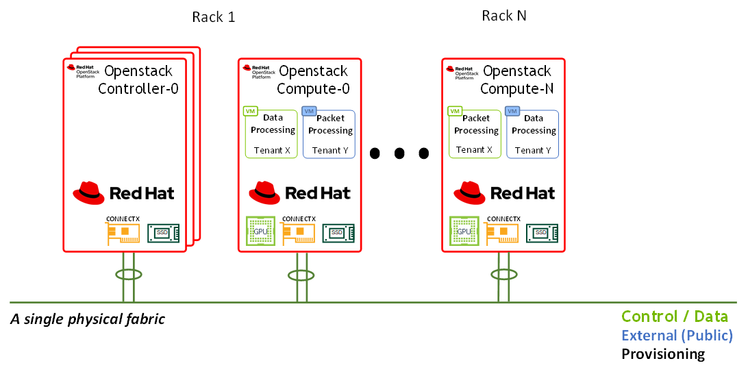
This document demonstrates the deployment of a large-scale OpenStack cloud over a single high-speed fabric.
The fabric provides the cloud a mix of L3-routed networks and L2-stretched EVPN networks -
L2-stretched networks are used for the "Deployment/Provisioning" network (as they greatly simplify DHCP and PXE operations) and for the "External" network (as they allow attaching a single external network segment to the cluster, typically a subnet that has real Internet addressing).
Red Hat OpenStack Platform (RH-OSP) is a cloud computing solution that enables the creation, deployment, scale and management of a secure and reliable public or private OpenStack-based cloud. This production-ready platform offers a tight integration with NVIDIA networking and data processing technologies.
The solution demonstrated in this article can be easily applied to diverse use cases, such as core or edge computing, with hardware accelerated packet and data processing for NFV, Big Data, and AI workloads over IP, DPDK, and RoCE stacks.
RH-OSP16.1 Release Notes
Red Hat OpenStack Platform 16.1, supports offloading of the OVS switching function to the SmartNIC hardware. This enhancement reduces the processing resources required and accelerates the data path. In Red Hat OpenStack Platform 16.1, this feature has graduated from Technology Preview and is now fully supported.
Downloadable Content
All configuration files used in this article can be found here: 47036708-1.0.0.zip
References
Red Hat OpenStack Platform 16.1 Installation Guide
Red Hat Openstack Platform 16.1 Spine Leaf Networking
QSG: High Availability with ASAP2 Enhanced SR-IOV (VF-LAG).
Solution Architecture
Key Components and Technologies
CONNECTX®-6 Dx is a member of the world-class, award-winning ConnectX series of network adapters. ConnectX-6 Dx delivers two ports of 10/25/40/50/100Gb/s or a single-port of 200Gb/s Ethernet connectivity paired with best-in-class hardware capabilities that accelerate and secure cloud and data center workloads.
NVIDIA Spectrum™ Ethernet Switch product family includes a broad portfolio of top-of-rack and aggregation switches, that can be deployed in layer-2 and layer-3 cloud designs, in overlay-based virtualized networks, or as part of high-performance, mission-critical ethernet storage fabrics.
LinkX® product family of cables and transceivers provides the industry’s most complete line of 10, 25, 40, 50, 100, 200, and 400GbE in Ethernet and EDR, HDR, and NDR in InfiniBand products for Cloud, HPC, Web 2.0, Enterprise, telco, storage, and artificial intelligence and data center applications. LinkX cables and transceivers are often used to link top-of-rack switches downwards to network adapters in NVIDIA GPUs and CPU servers, and storage and/or upwards in switch-to-switch applications throughout the network infrastructure.
CUMULUS Linux is the world’s most robust open networking operating system. It includes a comprehensive list of advanced, modern networking features, and is built for scale.
Red Hat OpenStack Platform is a cloud computing platform that virtualizes resources from industry-standard hardware, organizes those resources into clouds, and manages them so users can access what they need, when they need it.
Logical Design
A typical OpenStack deployment uses several infrastructure networks, as portrayed in the following diagram:
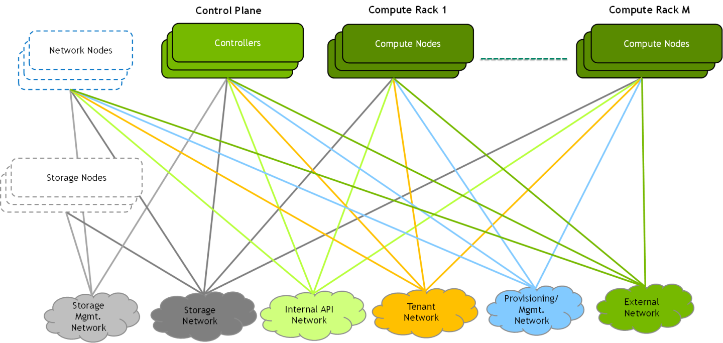
A straight forward approach would be to use a separate physical network for each infrastructure network above, but this is not practical. Most deployments converge several networks onto a physical fabric and typically use one or more 1/10GbE fabrics and sometimes an additional high-speed fabric (25/100/200GbE).
In this document, we will demonstrate a deployment that converges all the below networks onto a single 100/200GbE high-speed fabric.
Network Fabric Design
Note
In this network design, Compute Nodes are connected to the External network as required for Distributed Virtual Routing (DVR) configuration. For more information, please refer to Red Hat Openstack Platform DVR.
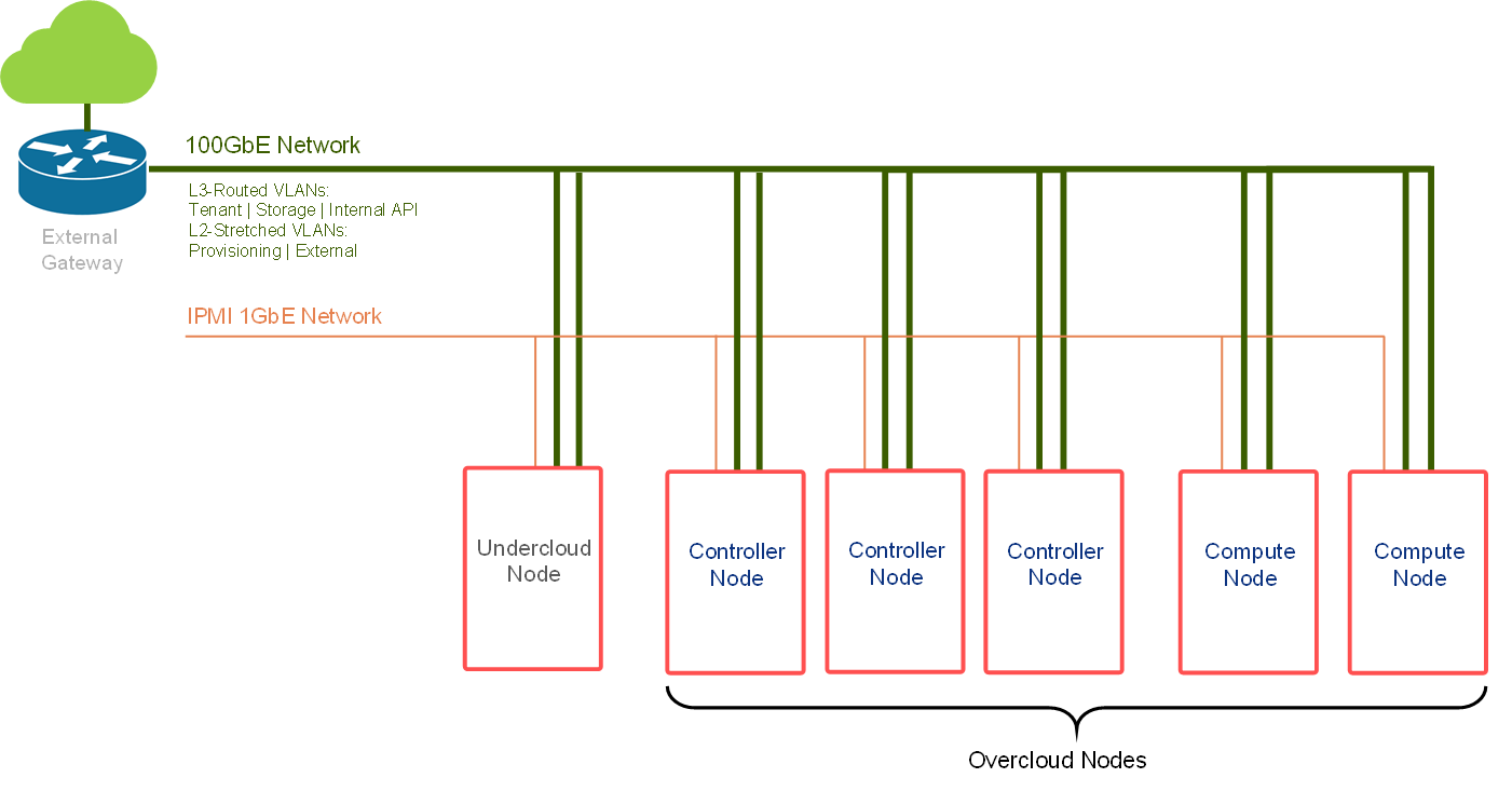
Routed Spine-Leaf networking architecture is used in this RDG for high speed Control and Data networks. However, the provisioning and External network use L2-Stretched EVPN networks. For more information, please see Red Hat Openstack Platform Spine Leaf Networking.
The deployment includes two separate networking layers:
High-speed Ethernet fabric
IPMI and switch management (not covered in this document)
The high-speed fabric described in this document contains the following building blocks:
Routed Spine-Leaf networking architecture
2 x MSN3700C Spine switches
L3 BGP unnumbered with ECMP is configured on the Leaf and Spine switches to allow multipath routing between racks located on different L3 network segments
2 x MSN2100 Leaf switches per rack in MLAG topology
2 x 100GbE ports for MLAG peerlink between Leaf pairs
L3 VRR VLAN interfaces on a Leaf pair that is used as the default gateway for the host servers VLAN interfaces
VXLAN VTEPs with BGP EVPN control plane for creating stretch L2 networks for provisioning and for the external network
Host servers with 2 x 100GbE ports configured with LACP Active-Active bonding with multiple VLAN interfaces
The entire fabric is configured to support Jumbo Frames (MTU=9000)

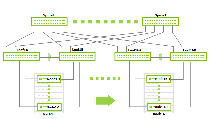
This document will demonstrate a minimalistic scale of two racks with 1 compute node each. Though using the same design, the fabric can be scaled to accommodate up to 236 compute nodes with 2x100GbE connectivity and a non-blocking fabric.
This is a diagram demonstrating the maximum possible scale for a non-blocking deployment that uses 2x100GbE to the hosts (16 racks, 15 servers each using 15 spines and 32 leafs):
Host Accelerated Bonding Logical Design
In order to use the MLAG-based network high availability, the hosts must have two high-speed interfaces that are bonded together with an LACP bond.
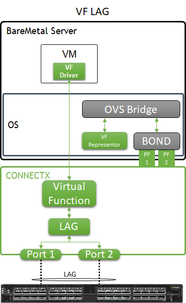
In the solution described in this article, enhanced SR-IOV with bonding support ( ASAP 2 VF-LAG) is used to offload network processing from the host and VM into the network adapter hardware, while providing fast data plane with high availability functionality.
Two Virtual Functions, each on a different physical port, are bonded and allocated to the VM as a single LAGed VF. The bonded interface is connected to a single or multiple ToR switches, using Active-Standby or Active-Active bond modes.
For additional information, refer to QSG: High Availability with ASAP2 Enhanced SR-IOV (VF-LAG).
Host and Application Logical Design
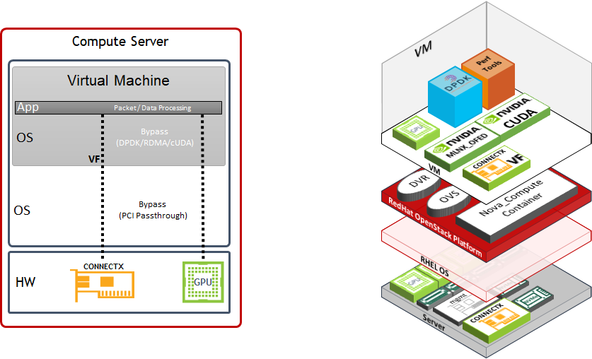
Compute host components:
ConnectX-6 Dx High Speed NIC with a dual physical port that is configured with LACP bonding in MLAG topology and providing VF-LAG redundancy to the VM
Storage Drives for local OS usage
RHEL as a base OS
Red Hat OpenStack Platform containerized software stack with the following:
KVM-based hypervisor
Openvswitch (OVS) with hardware offload support
Distributed Virtual Routing (DVR) configuration
Virtual Machine components:
CentOS 7.x/8.x as a base OS
SR-IOV VF allocated using PCI passthrough which allows to bypass the compute server hypervisor
perftest-tools Performance and benchmark testing tool set
Software Stack Components
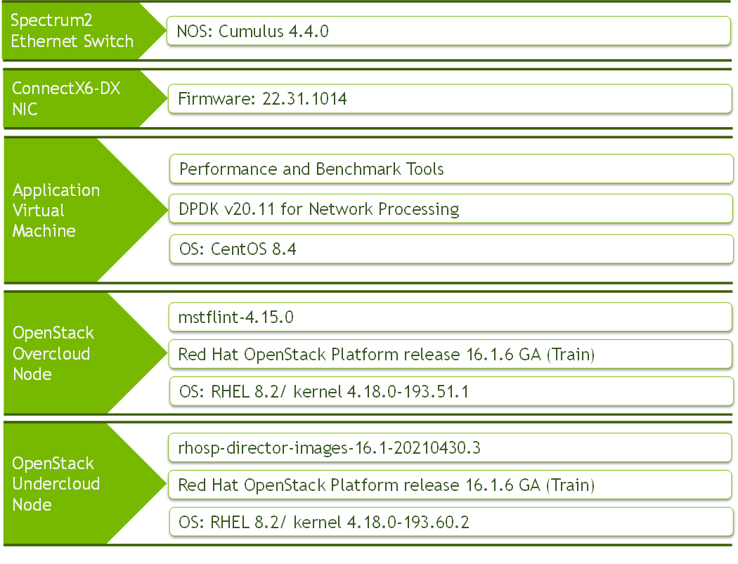
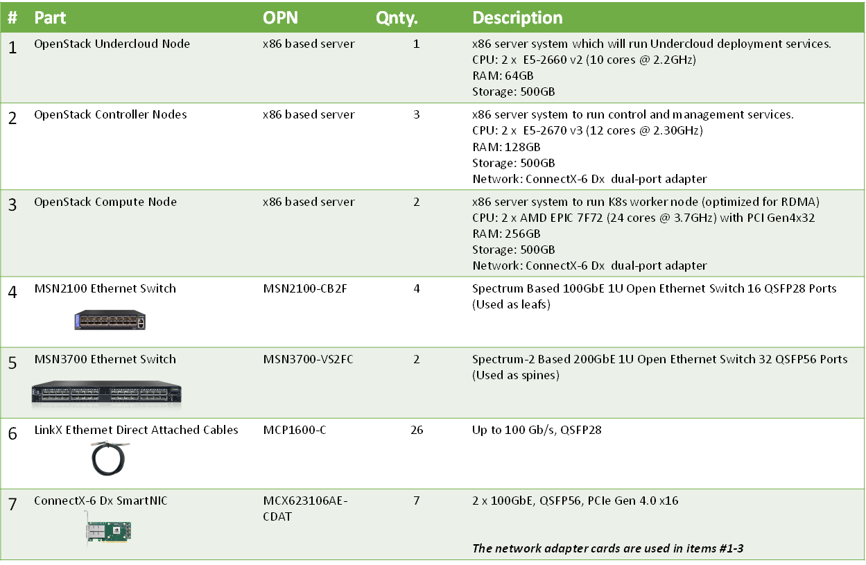
Bill of Materials
Deployment and Configuration
|
Spines |
|||
|
Hostname |
Router ID |
Autonomous System |
Downlinks |
|
spine1 |
10.10.10.101/32 |
65199 |
swp1-4 |
|
spine2 |
10.10.10.102/32 |
65199 |
swp1-4 |
|
Leafs |
||||||||
|
Rack |
Hostname |
Router ID |
Autonomous System |
Uplinks |
ISL ports |
CLAG System MAC |
CLAG Priority |
VXLAN_Anycast_IP |
|
1 |
leaf1a |
10.10.10.1/32 |
65100 |
swp13-14 |
swp15-16 |
44:38:39:BE:EF:AA |
1000 |
10.0.0.10 |
|
1 |
leaf1b |
10.10.10.2/32 |
65100 |
swp13-14 |
swp15-16 |
44:38:39:BE:EF:AA |
32768 |
10.0.0.10 |
|
2 |
leaf2a |
10.10.10.3/32 |
65101 |
swp13-14 |
swp15-16 |
44:38:39:BE:EF:BB |
1000 |
10.0.0.20 |
|
2 |
leaf2b |
10.10.10.4/32 |
65101 |
swp13-14 |
swp15-16 |
44:38:39:BE:EF:BB |
32768 |
10.0.0.20 |
|
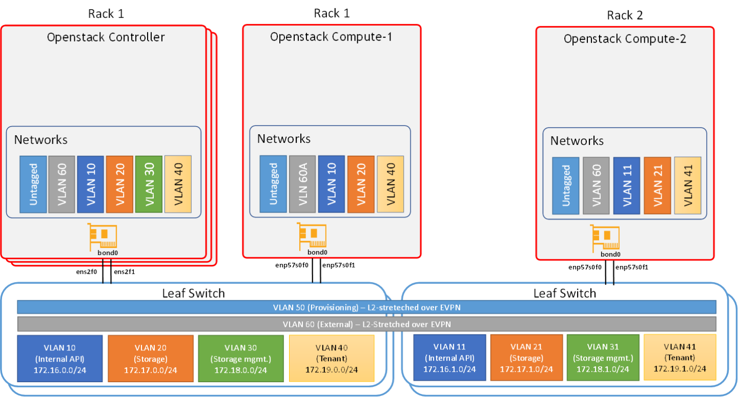
L3-Routed VLANs |
|||||
|
VLAN ID |
Virtual MAC |
Virtual IP |
Primary Router IP |
Secondary Router IP |
Purpose |
|
10 |
00:00:5E:00:01:00 |
172.16.0.254/24 |
172.16.0.252/24 |
172.16.0.253/24 |
Internal_API |
|
20 |
00:00:5E:00:01:00 |
172.17.0.254/24 |
172.17.0.252/24 |
172.17.0.253/24 |
Storage |
|
30 |
00:00:5E:00:01:00 |
172.18.0.254/24 |
172.18.0.252/24 |
172.18.0.253/24 |
Storage Mgmt |
|
40 |
00:00:5E:00:01:00 |
172.19.0.254/24 |
172.19.0.252/24 |
172.19.0.253/24 |
Tenant |
|
11 |
00:00:5E:00:01:01 |
172.16.1.254/24 |
172.16.1.252/24 |
172.16.1.253/24 |
Internal_API |
|
21 |
00:00:5E:00:01:01 |
172.17.1.254/24 |
172.17.1.252/24 |
172.17.1.253/24 |
Storage |
|
31 |
00:00:5E:00:01:01 |
172.18.1.254/24 |
172.18.1.252/24 |
172.18.1.253/24 |
Storage Mgmt |
|
41 |
00:00:5E:00:01:01 |
172.19.1.254/24 |
172.19.1.252/24 |
172.19.1.253/24 |
Tenant |
|
L2-Stretched VLANs (EVPN) |
|||
|
VLAN ID |
VNI |
Used Subnet |
Purpose |
|
50 |
10050 |
192.168.24.0/24 |
Provisioning (generated by the undercloud node) |
|
60 |
10060 |
172.60.0.0/24 |
External/Internet Access The undercloud node has an address in this subnet (172.60.0.1) and its default gateway is 172.60.0.254 |
|
Server Ports |
||||
|
Rack |
VLAN ID |
Access Ports |
Trunk Ports |
Network Purpose |
|
1 |
10 |
swp1-5 |
Internal API |
|
|
1 |
20 |
swp1-5 |
Storage |
|
|
1 |
30 |
swp1-5 |
Storage Mgmt |
|
|
1 |
40 |
swp1-5 |
Tenant |
|
|
1 |
50 |
swp1-5 |
Provisioning/Mgmt (Undercloud-Overcloud) |
|
|
1 |
60 |
swp1-5 |
External |
|
|
2 |
11 |
swp1 |
Internal API |
|
|
2 |
21 |
swp1 |
Storage |
|
|
2 |
31 |
swp1 |
Storage Mgmt |
|
|
2 |
41 |
swp1 |
Tenant |
|
|
2 |
50 |
swp1 |
Provisioning/Mgmt (Undercloud-Overcloud) |
|
|
2 |
60 |
swp1 |
External |
|
|
Server Wiring |
||
|
Rack1 |
Director Node (Undercloud) |
ens2f0 → Leaf1A, swp1 ens2f1 → Leaf1B, swp1 |
|
Controller-1 |
ens2f0 → Leaf1A, swp2 ens2f1 → Leaf1B, swp2 |
|
|
Controller-2 |
ens2f0 → Leaf1A, swp3 ens2f1 → Leaf1B, swp3 |
|
|
Controller-3 |
ens2f0 → Leaf1A, swp4 ens2f1 → Leaf1B, swp4 |
|
|
Compute-1 |
enp57s0f0 → Leaf1A, swp5 enp57s0f1 → Leaf1B, swp5 |
|
|
Rack2 |
Compute-2 |
enp57s0f1 → Leaf2A, swp1 enp57s0f0 → Leaf2A, swp1 |
Wiring
The wiring principal for the high-speed Ethernet fabric is as follows:
Each server in the racks is wired to two leaf(or "TOR") switch
Leaf switches are interconnected using two ports (to create an MLAG)
Every leaf is wired to all the spines
Below is the full wiring diagram for the demonstrated fabric:
Network/Fabric
Updating Cumulus Linux
As a best practice, make sure to use the latest released Cumulus Linux NOS version.
Please see this guide on how to upgrade Cumulus Linux.
Configuring the Cumulus Linux switch
Make sure your Cumulus Linux switch has passed its initial configuration stages (for additional information, see the Quick-Start Guide for version 4.4):
License installation
Creation of switch interfaces (e.g., swp1-32)
The configuration of the spine switches includes the following:
Routing & BGP
EVPN
Downlinks configuration
The configuration of the leaf switches includes the following:
Routing & BGP
EVPN
Uplinks configuration
MLAG
L3-Routed VLANs
L2-Stretched VLANs
Bonds configuration
Following are the configuration commands:
The configuration below does not include the connection of an external router/gateway for external/Internet connectivity
The "external" network (stretched L2 over VLAN 60) is assumed to have a gateway (at 172.60.0.254) and to provide Internet connectivity for the cluster
The director (undercloud) node has an interface on VLAN 60 (bond0.60 with address 172.60.0.1)
Spine1 Console
            net add loopback lo ip address 10.10.10.101/32
net add routing defaults datacenter
net add routing log syslog informational
net add routing service integrated-vtysh-config
net add bgp autonomous-system 65199
net add bgp router-id 10.10.10.101
net add bgp neighbor underlay peer-group
net add bgp neighbor underlay remote-as external
net add interface swp1 mtu 9216
net add bgp neighbor swp1 interface peer-group underlay
net add interface swp2 mtu 9216
net add bgp neighbor swp2 interface peer-group underlay
net add interface swp3 mtu 9216
net add bgp neighbor swp3 interface peer-group underlay
net add interface swp4 mtu 9216
net add bgp neighbor swp4 interface peer-group underlay
net add bgp ipv4 unicast redistribute connected
net add bgp ipv6 unicast neighbor underlay activate
net add bgp l2vpn evpn  neighbor underlay activate
net add bgp l2vpn evpn  advertise-all-vni
net commit
Spine2 Console
            net add loopback lo ip address 10.10.10.102/32
net add routing defaults datacenter
net add routing log syslog informational
net add routing service integrated-vtysh-config
net add bgp autonomous-system 65199
net add bgp router-id 10.10.10.102
net add bgp neighbor underlay peer-group
net add bgp neighbor underlay remote-as external
net add interface swp1 mtu 9216
net add bgp neighbor swp1 interface peer-group underlay
net add interface swp2 mtu 9216
net add bgp neighbor swp2 interface peer-group underlay
net add interface swp3 mtu 9216
net add bgp neighbor swp3 interface peer-group underlay
net add interface swp4 mtu 9216
net add bgp neighbor swp4 interface peer-group underlay
net add bgp ipv4 unicast redistribute connected
net add bgp ipv6 unicast neighbor underlay activate
net add bgp l2vpn evpn  neighbor underlay activate
net add bgp l2vpn evpn  advertise-all-vni
net commit
Leaf1A Console
            net add interface swp15,swp16 mtu 9216
net add bond peerlink bond slaves swp15,swp16
net add interface swp1 mtu 9216
net add bond bond1 bond slaves swp1
net add bond bond1 clag id 1
net add interface swp2 mtu 9216
net add bond bond2 bond slaves swp2
net add bond bond2 clag id 2
net add interface swp3 mtu 9216
net add bond bond3 bond slaves swp3
net add bond bond3 clag id 3
net add interface swp4 mtu 9216
net add bond bond4 bond slaves swp4
net add bond bond4 clag id 4
net add interface swp5 mtu 9216
net add bond bond5 bond slaves swp5
net add bond bond5 clag id 5
net add bond bond1,bond2,bond3,bond4,bond5 bond lacp-bypass-allow
net add bond bond1,bond2,bond3,bond4,bond5 stp bpduguard
net add bond bond1,bond2,bond3,bond4,bond5 stp portadminedge
net add bridge bridge ports bond1,bond2,bond3,bond4,bond5,peerlink
net add bridge bridge vlan-aware
net add bgp autonomous-system 65100
net add routing defaults datacenter
net add routing log syslog informational
net add routing service integrated-vtysh-config
net add bgp router-id 10.10.10.1
net add bgp bestpath as-path multipath-relax
net add bgp neighbor underlay peer-group
net add bgp neighbor underlay remote-as external
net add bgp neighbor peerlink.4094 interface remote-as internal
net add interface swp13 mtu 9216
net add bgp neighbor swp13 interface peer-group underlay
net add interface swp14 mtu 9216
net add bgp neighbor swp14 interface peer-group underlay
net add bgp ipv4 unicast redistribute connected
net add loopback lo ip address 10.10.10.1/32
net add interface peerlink.4094 clag backup-ip 10.10.10.2
net add interface peerlink.4094 clag priority 1000
net add interface peerlink.4094 clag sys-mac 44:38:39:BE:EF:AA
net add interface peerlink.4094 clag peer-ip linklocal
net add interface peerlink.4094 clag args --initDelay 10
net add bridge bridge vids 10
net add vlan 10 ip address 172.16.0.252/24
net add vlan 10 ip address-virtual 00:00:5E:00:01:00 172.16.0.254/24
net add vlan 10 vlan-id 10
net add vlan 10 vlan-raw-device bridge
net add bridge bridge vids 20
net add vlan 20 ip address 172.17.0.252/24
net add vlan 20 ip address-virtual 00:00:5E:00:01:00 172.17.0.254/24
net add vlan 20 vlan-id 20
net add vlan 20 vlan-raw-device bridge
net add bridge bridge vids 30
net add vlan 30 ip address 172.18.0.252/24
net add vlan 30 ip address-virtual 00:00:5E:00:01:00 172.18.0.254/24
net add vlan 30 vlan-id 30
net add vlan 30 vlan-raw-device bridge
net add bridge bridge vids 40
net add vlan 40 ip address 172.19.0.252/24
net add vlan 40 ip address-virtual 00:00:5E:00:01:00 172.19.0.254/24
net add vlan 40 vlan-id 40
net add vlan 40 vlan-raw-device bridge
net add bgp l2vpn evpn  neighbor underlay activate
net add bgp l2vpn evpn  neighbor peerlink.4094 activate
net add bgp l2vpn evpn  advertise-all-vni
net add bgp l2vpn evpn  advertise-default-gw
net add bgp l2vpn evpn  advertise ipv4 unicast
net add bgp ipv6 unicast neighbor underlay activate
net add loopback lo clag vxlan-anycast-ip 10.0.0.10
net add loopback lo vxlan local-tunnelip 10.10.10.1
net add vlan 60 vlan-id 60
net add vlan 60 vlan-raw-device bridge
net add vlan 50 vlan-id 50
net add vlan 50 vlan-raw-device bridge
net add vxlan vtep60 vxlan id 10060
net add vxlan vtep50 vxlan id 10050
net add vxlan vtep60,50 bridge arp-nd-suppress on
net add vxlan vtep60,50 bridge learning off
net add vxlan vtep60,50 stp bpduguard
net add vxlan vtep60,50 stp portbpdufilter
net add vxlan vtep60,50 vxlan local-tunnelip 10.10.10.1
net add vxlan vtep60 bridge access 60
net add vxlan vtep50 bridge access 50
net add bridge bridge ports vtep60,vtep50
net add bridge bridge vids 60,50
net add bond bond1-5 bridge pvid 50
net commit
Leaf1B Console
            net add interface swp15,swp16 mtu 9216
net add bond peerlink bond slaves swp15,swp16
net add interface swp1 mtu 9216
net add bond bond1 bond slaves swp1
net add bond bond1 clag id 1
net add interface swp2 mtu 9216
net add bond bond2 bond slaves swp2
net add bond bond2 clag id 2
net add interface swp3 mtu 9216
net add bond bond3 bond slaves swp3
net add bond bond3 clag id 3
net add interface swp4 mtu 9216
net add bond bond4 bond slaves swp4
net add bond bond4 clag id 4
net add interface swp5 mtu 9216
net add bond bond5 bond slaves swp5
net add bond bond5 clag id 5
net add bond bond1,bond2,bond3,bond4,bond5 bond lacp-bypass-allow
net add bond bond1,bond2,bond3,bond4,bond5 stp bpduguard
net add bond bond1,bond2,bond3,bond4,bond5 stp portadminedge
net add bridge bridge ports bond1,bond2,bond3,bond4,bond5,peerlink
net add bridge bridge vlan-aware
net add bgp autonomous-system 65100
net add routing defaults datacenter
net add routing log syslog informational
net add routing service integrated-vtysh-config
net add bgp router-id 10.10.10.2
net add bgp bestpath as-path multipath-relax
net add bgp neighbor underlay peer-group
net add bgp neighbor underlay remote-as external
net add bgp neighbor peerlink.4094 interface remote-as internal
net add interface swp13 mtu 9216
net add bgp neighbor swp13 interface peer-group underlay
net add interface swp14 mtu 9216
net add bgp neighbor swp14 interface peer-group underlay
net add bgp ipv4 unicast redistribute connected
net add loopback lo ip address 10.10.10.2/32
net add interface peerlink.4094 clag backup-ip 10.10.10.1
net add interface peerlink.4094 clag priority 32768
net add interface peerlink.4094 clag sys-mac 44:38:39:BE:EF:AA
net add interface peerlink.4094 clag peer-ip linklocal
net add interface peerlink.4094 clag args --initDelay 10
net add bridge bridge vids 10
net add vlan 10 ip address 172.16.0.253/24
net add vlan 10 ip address-virtual 00:00:5E:00:01:00 172.16.0.254/24
net add vlan 10 vlan-id 10
net add vlan 10 vlan-raw-device bridge
net add bridge bridge vids 20
net add vlan 20 ip address 172.17.0.253/24
net add vlan 20 ip address-virtual 00:00:5E:00:01:00 172.17.0.254/24
net add vlan 20 vlan-id 20
net add vlan 20 vlan-raw-device bridge
net add bridge bridge vids 30
net add vlan 30 ip address 172.18.0.253/24
net add vlan 30 ip address-virtual 00:00:5E:00:01:00 172.18.0.254/24
net add vlan 30 vlan-id 30
net add vlan 30 vlan-raw-device bridge
net add bridge bridge vids 40
net add vlan 40 ip address 172.19.0.253/24
net add vlan 40 ip address-virtual 00:00:5E:00:01:00 172.19.0.254/24
net add vlan 40 vlan-id 40
net add vlan 40 vlan-raw-device bridge
net add bgp l2vpn evpn  neighbor underlay activate
net add bgp l2vpn evpn  neighbor peerlink.4094 activate
net add bgp l2vpn evpn  advertise-all-vni
net add bgp l2vpn evpn  advertise-default-gw
net add bgp l2vpn evpn  advertise ipv4 unicast
net add bgp ipv6 unicast neighbor underlay activate
net add loopback lo clag vxlan-anycast-ip 10.0.0.10
net add loopback lo vxlan local-tunnelip 10.10.10.2
net add vlan 60 vlan-id 60
net add vlan 60 vlan-raw-device bridge
net add vlan 50 vlan-id 50
net add vlan 50 vlan-raw-device bridge
net add vxlan vtep60 vxlan id 10060
net add vxlan vtep50 vxlan id 10050
net add vxlan vtep60,50 bridge arp-nd-suppress on
net add vxlan vtep60,50 bridge learning off
net add vxlan vtep60,50 stp bpduguard
net add vxlan vtep60,50 stp portbpdufilter
net add vxlan vtep60,50 vxlan local-tunnelip 10.10.10.2
net add vxlan vtep60 bridge access 60
net add vxlan vtep50 bridge access 50
net add bridge bridge ports vtep60,vtep50
net add bridge bridge vids 60,50
net add bond bond1-5 bridge pvid 50
net commit
Leaf2A Console
            net add interface swp15,swp16 mtu 9216
net add bond peerlink bond slaves swp15,swp16
net add interface swp1 mtu 9216
net add bond bond1 bond slaves swp1
net add bond bond1 clag id 1
net add bond bond1 bond lacp-bypass-allow
net add bond bond1 stp bpduguard
net add bond bond1 stp portadminedge
net add bridge bridge ports bond1,peerlink
net add bridge bridge vlan-aware
net add bgp autonomous-system 65101
net add routing defaults datacenter
net add routing log syslog informational
net add routing service integrated-vtysh-config
net add bgp router-id 10.10.10.3
net add bgp bestpath as-path multipath-relax
net add bgp neighbor underlay peer-group
net add bgp neighbor underlay remote-as external
net add bgp neighbor peerlink.4094 interface remote-as internal
net add interface swp13 mtu 9216
net add bgp neighbor swp13 interface peer-group underlay
net add interface swp14 mtu 9216
net add bgp neighbor swp14 interface peer-group underlay
net add bgp ipv4 unicast redistribute connected
net add loopback lo ip address 10.10.10.3/32
net add interface peerlink.4094 clag backup-ip 10.10.10.4
net add interface peerlink.4094 clag priority 1000
net add interface peerlink.4094 clag sys-mac 44:38:39:BE:EF:BB
net add interface peerlink.4094 clag peer-ip linklocal
net add interface peerlink.4094 clag args --initDelay 10
net add bridge bridge vids 11
net add vlan 11 ip address 172.16.1.252/24
net add vlan 11 ip address-virtual 00:00:5E:00:01:01 172.16.1.254/24
net add vlan 11 vlan-id 11
net add vlan 11 vlan-raw-device bridge
net add bridge bridge vids 21
net add vlan 21 ip address 172.17.1.252/24
net add vlan 21 ip address-virtual 00:00:5E:00:01:01 172.17.1.254/24
net add vlan 21 vlan-id 21
net add vlan 21 vlan-raw-device bridge
net add bridge bridge vids 31
net add vlan 31 ip address 172.18.1.252/24
net add vlan 31 ip address-virtual 00:00:5E:00:01:01 172.18.1.254/24
net add vlan 31 vlan-id 31
net add vlan 31 vlan-raw-device bridge
net add bridge bridge vids 41
net add vlan 41 ip address 172.19.1.252/24
net add vlan 41 ip address-virtual 00:00:5E:00:01:01 172.19.1.254/24
net add vlan 41 vlan-id 41
net add vlan 41 vlan-raw-device bridge
net add bgp l2vpn evpn  neighbor underlay activate
net add bgp l2vpn evpn  neighbor peerlink.4094 activate
net add bgp l2vpn evpn  advertise-all-vni
net add bgp l2vpn evpn  advertise-default-gw
net add bgp l2vpn evpn  advertise ipv4 unicast
net add bgp ipv6 unicast neighbor underlay activate
net add loopback lo clag vxlan-anycast-ip 10.0.0.20
net add loopback lo vxlan local-tunnelip 10.10.10.3
net add vlan 60 vlan-id 60
net add vlan 60 vlan-raw-device bridge
net add vlan 50 vlan-id 50
net add vlan 50 vlan-raw-device bridge
net add vxlan vtep60 vxlan id 10060
net add vxlan vtep50 vxlan id 10050
net add vxlan vtep60,50 bridge arp-nd-suppress on
net add vxlan vtep60,50 bridge learning off
net add vxlan vtep60,50 stp bpduguard
net add vxlan vtep60,50 stp portbpdufilter
net add vxlan vtep60,50 vxlan local-tunnelip 10.10.10.3
net add vxlan vtep60 bridge access 60
net add vxlan vtep50 bridge access 50
net add bridge bridge ports vtep60,vtep50
net add bridge bridge vids 60,50
net add bond bond1 bridge pvid 50
net commit
Leaf2B Console
            net add interface swp15,swp16 mtu 9216
net add bond peerlink bond slaves swp15,swp16
net add interface swp1 mtu 9216
net add bond bond1 bond slaves swp1
net add bond bond1 clag id 1
net add bond bond1 bond lacp-bypass-allow
net add bond bond1 stp bpduguard
net add bond bond1 stp portadminedge
net add bridge bridge ports bond1,peerlink
net add bridge bridge vlan-aware
net add bgp autonomous-system 65101
net add routing defaults datacenter
net add routing log syslog informational
net add routing service integrated-vtysh-config
net add bgp router-id 10.10.10.4
net add bgp bestpath as-path multipath-relax
net add bgp neighbor underlay peer-group
net add bgp neighbor underlay remote-as external
net add bgp neighbor peerlink.4094 interface remote-as internal
net add interface swp13 mtu 9216
net add bgp neighbor swp13 interface peer-group underlay
net add interface swp14 mtu 9216
net add bgp neighbor swp14 interface peer-group underlay
net add bgp ipv4 unicast redistribute connected
net add loopback lo ip address 10.10.10.4/32
net add interface peerlink.4094 clag backup-ip 10.10.10.3
net add interface peerlink.4094 clag priority 32768
net add interface peerlink.4094 clag sys-mac 44:38:39:BE:EF:BB
net add interface peerlink.4094 clag peer-ip linklocal
net add interface peerlink.4094 clag args --initDelay 10
net add bridge bridge vids 11
net add vlan 11 ip address 172.16.1.253/24
net add vlan 11 ip address-virtual 00:00:5E:00:01:01 172.16.1.254/24
net add vlan 11 vlan-id 11
net add vlan 11 vlan-raw-device bridge
net add bridge bridge vids 21
net add vlan 21 ip address 172.17.1.253/24
net add vlan 21 ip address-virtual 00:00:5E:00:01:01 172.17.1.254/24
net add vlan 21 vlan-id 21
net add vlan 21 vlan-raw-device bridge
net add bridge bridge vids 31
net add vlan 31 ip address 172.18.1.253/24
net add vlan 31 ip address-virtual 00:00:5E:00:01:01 172.18.1.254/24
net add vlan 31 vlan-id 31
net add vlan 31 vlan-raw-device bridge
net add bridge bridge vids 41
net add vlan 41 ip address 172.19.1.253/24
net add vlan 41 ip address-virtual 00:00:5E:00:01:01 172.19.1.254/24
net add vlan 41 vlan-id 41
net add vlan 41 vlan-raw-device bridge
net add bgp l2vpn evpn  neighbor underlay activate
net add bgp l2vpn evpn  neighbor peerlink.4094 activate
net add bgp l2vpn evpn  advertise-all-vni
net add bgp l2vpn evpn  advertise-default-gw
net add bgp l2vpn evpn  advertise ipv4 unicast
net add bgp ipv6 unicast neighbor underlay activate
net add loopback lo clag vxlan-anycast-ip 10.0.0.20
net add loopback lo vxlan local-tunnelip 10.10.10.4
net add vlan 60 vlan-id 60
net add vlan 60 vlan-raw-device bridge
net add vlan 50 vlan-id 50
net add vlan 50 vlan-raw-device bridge
net add vxlan vtep60 vxlan id 10060
net add vxlan vtep50 vxlan id 10050
net add vxlan vtep60,50 bridge arp-nd-suppress on
net add vxlan vtep60,50 bridge learning off
net add vxlan vtep60,50 stp bpduguard
net add vxlan vtep60,50 stp portbpdufilter
net add vxlan vtep60,50 vxlan local-tunnelip 10.10.10.4
net add vxlan vtep60 bridge access 60
net add vxlan vtep50 bridge access 50
net add bridge bridge ports vtep60,vtep50
net add bridge bridge vids 60,50
net add bond bond1 bridge pvid 50
net commit
Repeat the following commands on all the leafs:
Leaf Switch Console
            cumulus@leaf1a:mgmt:~$ net show clag
The peer is alive
     Our Priority, ID, and Role: 1000 1c:34:da:b4:09:40 primary
    Peer Priority, ID, and Role: 32768 1c:34:da:b4:06:40 secondary
          Peer Interface and IP: peerlink.4094 fe80::1e34:daff:feb4:640 (linklocal)
               VxLAN Anycast IP: 10.0.0.10
                      Backup IP: 10.10.10.2 (active)
                     System MAC: 44:38:39:be:ef:aa

CLAG Interfaces
Our Interface      Peer Interface     CLAG Id   Conflicts              Proto-Down Reason
----------------   ----------------   -------   --------------------   -----------------
           bond1   bond1              1         -                      -
           bond2   bond2              2         -                      -
           bond3   bond3              3         -                      -
           bond4   bond4              4         -                      -
           bond5   bond5              5         -                      -
          vtep50   vtep50             -         -                      -
          vtep60   vtep60             -         -                      -

cumulus@leaf1a:mgmt:~$ net show route
show ip route
=============
Codes: K - kernel route, C - connected, S - static, R - RIP,
       O - OSPF, I - IS-IS, B - BGP, E - EIGRP, N - NHRP,
       T - Table, v - VNC, V - VNC-Direct, A - Babel, D - SHARP,
       F - PBR, f - OpenFabric,
       > - selected route, * - FIB route, q - queued, r - rejected, b - backup
       t - trapped, o - offload failure
C>* 10.0.0.10/32 is directly connected, lo, 01w5d21h
B>* 10.0.0.20/32 [20/0] via fe80::1e34:daff:feb3:ff6c, swp30, weight 1, 01w5d21h
  *                     via fe80::1e34:daff:feb4:6c, swp29, weight 1, 01w5d21h
C>* 10.10.10.1/32 is directly connected, lo, 01w6d19h
B>* 10.10.10.2/32 [200/0] via fe80::1e34:daff:feb4:640, peerlink.4094, weight 1, 01w5d21h
B>* 10.10.10.3/32 [20/0] via fe80::1e34:daff:feb3:ff6c, swp30, weight 1, 01w5d21h
  *                      via fe80::1e34:daff:feb4:6c, swp29, weight 1, 01w5d21h
B>* 10.10.10.4/32 [20/0] via fe80::1e34:daff:feb3:ff6c, swp30, weight 1, 01w5d21h
  *                      via fe80::1e34:daff:feb4:6c, swp29, weight 1, 01w5d21h
B>* 10.10.10.101/32 [20/0] via fe80::1e34:daff:feb4:6c, swp29, weight 1, 01w5d21h
B>* 10.10.10.102/32 [20/0] via fe80::1e34:daff:feb3:ff6c, swp30, weight 1, 01w5d21h
C * 172.16.0.0/24 [0/1024] is directly connected, vlan10-v0, 01w5d21h
C>* 172.16.0.0/24 is directly connected, vlan10, 01w5d21h
B>* 172.16.1.0/24 [20/0] via fe80::1e34:daff:feb3:ff6c, swp30, weight 1, 01w5d21h
  *                      via fe80::1e34:daff:feb4:6c, swp29, weight 1, 01w5d21h
C * 172.17.0.0/24 [0/1024] is directly connected, vlan20-v0, 01w5d21h
C>* 172.17.0.0/24 is directly connected, vlan20, 01w5d21h
B>* 172.17.1.0/24 [20/0] via fe80::1e34:daff:feb3:ff6c, swp30, weight 1, 01w5d21h
  *                      via fe80::1e34:daff:feb4:6c, swp29, weight 1, 01w5d21h
C * 172.18.0.0/24 [0/1024] is directly connected, vlan30-v0, 01w5d21h
C>* 172.18.0.0/24 is directly connected, vlan30, 01w5d21h
B>* 172.18.1.0/24 [20/0] via fe80::1e34:daff:feb3:ff6c, swp30, weight 1, 01w5d21h
  *                      via fe80::1e34:daff:feb4:6c, swp29, weight 1, 01w5d21h
C * 172.19.0.0/24 [0/1024] is directly connected, vlan40-v0, 01w5d21h
C>* 172.19.0.0/24 is directly connected, vlan40, 01w5d21h
B>* 172.19.1.0/24 [20/0] via fe80::1e34:daff:feb3:ff6c, swp30, weight 1, 01w5d21h
  *                      via fe80::1e34:daff:feb4:6c, swp29, weight 1, 01w5d21h


show ipv6 route
===============
Codes: K - kernel route, C - connected, S - static, R - RIPng,
       O - OSPFv3, I - IS-IS, B - BGP, N - NHRP, T - Table,
       v - VNC, V - VNC-Direct, A - Babel, D - SHARP, F - PBR,
       f - OpenFabric,
       > - selected route, * - FIB route, q - queued, r - rejected, b - backup
       t - trapped, o - offload failure
C * fe80::/64 is directly connected, vlan50, 01w5d21h
C * fe80::/64 is directly connected, vlan60, 01w5d21h
C * fe80::/64 is directly connected, vlan40, 01w5d21h
C * fe80::/64 is directly connected, vlan40-v0, 01w5d21h
C * fe80::/64 is directly connected, vlan30-v0, 01w6d19h
C * fe80::/64 is directly connected, vlan30, 01w6d19h
C * fe80::/64 is directly connected, vlan20-v0, 01w6d19h
C * fe80::/64 is directly connected, vlan20, 01w6d19h
C * fe80::/64 is directly connected, vlan10-v0, 01w6d19h
C * fe80::/64 is directly connected, vlan10, 01w6d19h
C * fe80::/64 is directly connected, bridge, 01w6d19h
C * fe80::/64 is directly connected, peerlink.4094, 01w6d19h
C * fe80::/64 is directly connected, swid0_eth, 01w6d19h
C * fe80::/64 is directly connected, swp30, 01w6d19h
C>* fe80::/64 is directly connected, swp29, 01w6d19h
Host Preparation
In order to achieve optimal results for DPDK use cases, the compute node must be correctly optimized for DPDK performance.
The optimization might require specific BIOS and NIC Firmware settings. Please refer to the official DPDK performance document provided by your CPU vendor.
For our deployment we used the following document from AMD: https://www.amd.com/system/files/documents/epyc-7Fx2-processors-dpdk-nw-performance-brief.pdf
Please note that the host boot settings (Linux grub command line) are done later on as part of the overcloud image configuration and that the hugepages allocation is done on the actual VM used for testing.
OpenStack Deployment
The RedHat OpenStack Platform (RHOSP) version 16.1 will be used.
The deployment is divided into three major steps:
Installing the director node
Deploying the undercloud on the director node
Deploying the overcloud using the undercloud
Make sure that the BIOS settings on the worker nodes servers have SR-IOV enabled and that the servers are tuned for maximum performance.
All nodes which belong to the same profile (e.g., controller, compute) must have the same PCIe placement for the NIC and must expose the same interface name.
The director node needs to have the following network interfaces:
Untagged over bond0—used for provisioning the overcloud nodes (connected to stretched VLAN 50 on the switch)
Tagged VLAN 60 over bond0.60—used for Internet access over the external network segment (connected to stretched VLAN 60 on the switch)
An interface on the IPMI network—used for accessing to the bare metal nodes BMCs
Undercloud Director Installation
Follow RH-OSP Preparing for Director Installation up to Preparing Container Images.
Use the following environment file for OVS-based RH-OSP 16.1 container preparation. Remember to update your Red Hat registry credentials:
/home/stack/containers-prepare-parameter.yaml
            #global
parameter_defaults:
  ContainerImagePrepare:
  - push_destination: true
    excludes:
      - ceph
      - prometheus
    set:
      name_prefix: openstack-
      name_suffix: ''
      namespace: registry.redhat.io/rhosp-rhel8
      neutron_driver: null
      rhel_containers: false
      tag: '16.1'
    tag_from_label: '{version}-{release}'
  ContainerImageRegistryCredentials:
    registry.redhat.io:
      '<username>': '<password>'
Proceed with the director installation steps, described in RH-OSP Installing Director, up to the RH-OSP Installing Director execution.
The following undercloud configuration file was used in our deployment:
/home/stack/undercloud.conf
            [DEFAULT]
undercloud_hostname = rhosp-director.localdomain
local_ip = 192.168.24.1/24
network_gateway = 192.168.24.1
undercloud_public_host = 192.168.24.2
undercloud_admin_host = 192.168.24.3
undercloud_nameservers = 8.8.8.8,8.8.4.4
undercloud_ntp_servers = 10.211.0.134,10.211.0.124
subnets = ctlplane-subnet
local_subnet = ctlplane-subnet
generate_service_certificate = True
certificate_generation_ca = local
local_interface = bond0
inspection_interface = br-ctlplane
undercloud_debug = true
enable_tempest = false
enable_telemetry = false
enable_validations = true
enable_novajoin = false
clean_nodes = true
custom_env_files = /home/stack/custom-undercloud-params.yaml,/home/stack/ironic_ipmitool.yaml
container_images_file = /home/stack/containers-prepare-parameter.yaml

[auth]

[ctlplane-subnet]
cidr = 192.168.24.0/24
dhcp_start = 192.168.24.5
dhcp_end = 192.168.24.30
inspection_iprange = 192.168.24.100,192.168.24.120
gateway = 192.168.24.1
masquerade = true
Follow the instructions in RH-OSP Obtain Images for Overcloud Nodes (section 4.9.1, steps 1–3), without importing the images into the director yet.
Once obtained, follow the customization process described in RH-OSP Working with Overcloud Images:
Start from 3.3. QCOW: Installing virt-customize to director
Skip 3.4
Run 3.5. QCOW: Setting the root password (optional)
Run 3.6. QCOW: Registering the image
Run the following command to locate your subscription pool ID:
$ sudo subscription-manager list --available --all --matches="Red Hat OpenStack"
Replace [subscription-pool] in the below command with your relevant subscription pool ID:
$ virt-customize --selinux-relabel -a overcloud-full.qcow2 --run-command 'subscription-manager attach --pool [subscription-pool]'
Skip 3.7 and 3.8
Run the following command to add mstflint to overcloud image to allow the NIC firmware provisioning during overcloud deployment (similar to 3.9).
$ virt-customize --selinux-relabel -a overcloud-full.qcow2 --install mstflint
Notemstflint is required for the overcloud nodes to support the automatic NIC firmware upgrade by the cloud orchestration system during deployment.
Run 3.10. QCOW: Cleaning the subscription pool
Run 3.11. QCOW: Unregistering the image
Run 3.12. QCOW: Reset the machine ID
Run 3.13. Uploading the images to director
Undercloud Director Preparation for Automatic NIC Firmware Provisioning
Download the latest ConnectX NIC firmware binary file (fw-<NIC-Model>.bin) from NVIDIA Networking Firmware Download Site.
Create a directory named mlnx_fw under /var/lib/ironic/httpboot/ in the Director node, and place the firmware binary file in it.
Extract the connectx_first_boot.yaml file from the configuration files attached to this guide, and place it in the /home/stack/templates/ directory in the Director node
The connectx_first_boot.yaml file is called by another deployment configuration file ( env-ovs-dvr.yaml) , so please use the instructed location, or change the configuration files accordingly.
Overcloud Nodes Introspection
A full overcloud introspection procedure is described in RH-OSP Configuring a Basic Overcloud. In this RDG, the following configuration steps were used for introspecting overcloud bare metal nodes to be deployed later-on over two routed Spine-Leaf racks:
Prepare a bare metal inventory file - instackenv.json, with the overcloud nodes information. In this case, the inventory file is listing 5 bare metal nodes to be deployed as overcloud nodes: 3 controller nodes and 2 compute nodes (1 in each routed rack). Make sure to update the file with the IPMI servers addresses and credentials and with the MAC address of one of the physical ports in order to avoid issues in the introspection process:
instackenv.json
            {
    "nodes": [
        {
            "name": "controller-1",
            "pm_type":"ipmi",
            "pm_user":"root",
            "pm_password":"******",
            "pm_addr":"10.7.214.1",
			"ports":[
                {
                    "address":"<MAC_ADDRESS>",
                    "pxe_enabled":true
                }
            ]
        },
        {
            "name": "controller-2",
            "pm_type":"ipmi",
            "pm_user":"root",
            "pm_password":"******",
            "pm_addr":"10.7.214.2",
			"ports":[
                {
                    "address":"<MAC_ADDRESS>",
                    "pxe_enabled":true
                }
            ]
        },
        {
            "name": "controller-3",
            "pm_type":"ipmi",
            "pm_user":"root",
            "pm_password":"******",
            "pm_addr":"10.7.214.3",
			"ports":[
                {
                    "address":"<MAC_ADDRESS>",
                    "pxe_enabled":true
                }
            ]
        },
        {
            "name": "compute-1",
            "pm_type":"ipmi",
            "pm_user":"root",
            "pm_password":"******",
            "pm_addr":"10.7.214.4",
			"ports":[
                {
                    "address":"<MAC_ADDRESS>",
                    "pxe_enabled":true
                }
            ]
        },
        {
            "name": "compute-2",
            "pm_type":"ipmi",
            "pm_user":"root",
            "pm_password":"******",
            "pm_addr":"10.7.214.5",
			"ports":[
                {
                    "address":"<MAC_ADDRESS>",
                    "pxe_enabled":true
                }
            ]
        }
    ]
}
Import the overcloud baremetal nodes inventory, and wait until all nodes are listed in "manageable" state.
            [stack@rhosp-director ~]$ source ~/stackrc
(undercloud) [stack@rhosp-director ~]$ openstack overcloud node import /home/stack/instackenv.json
            $ openstack baremetal node list
+--------------------------------------+--------------+---------------+-------------+--------------------+-------------+
| UUID                                 | Name         | Instance UUID | Power State | Provisioning State | Maintenance |
+--------------------------------------+--------------+---------------+-------------+--------------------+-------------+
| 476c7659-abc2-4d8c-9532-1756abbfd18a | controller-1 | None          | power off   | manageable         | False       |
| 3cbb74e5-6508-4ec8-91a8-870dbf28baed | controller-2 | None          | power off   | manageable         | False       |
| 457b329e-f1bc-476a-996d-eb82a56998e8 | controller-3 | None          | power off   | manageable         | False       |
| 870445b7-650f-40fc-8ac2-5c3df700ccdc | compute-1    | None          | power off   | manageable         | False       |
| baa7356b-11ca-4cb0-b58c-16c110bbbea0 | compute-2    | None          | power off   | manageable         | False       |
+--------------------------------------+--------------+---------------+-------------+--------------------+-------------+
Start the baremetal nodes introspection:
$ openstack overcloud node introspect --all-manageable
Set the root device for deployment, and provide all baremetal nodes to reach "available" state:
            $ openstack overcloud node configure --all-manageable --instance-boot-option local --root-device largest
$ openstack overcloud node provide --all-manageable
Tag the controller nodes into the "control" profile, which is later mapped to the overcloud controller role:
            $ openstack baremetal node set --property capabilities='profile:control,boot_option:local' controller-1
$ openstack baremetal node set --property capabilities='profile:control,boot_option:local' controller-2
$ openstack baremetal node set --property capabilities='profile:control,boot_option:local' controller-3
WarningNote: The Role to Profile mapping is specified in the node-info.yaml file used during the overcloud deployment.
Create a new compute flavor, and tag one compute node into the "compute-r0" profile, which is later mapped to the overcloud "compute in rack 0" role:
            $ openstack flavor create --id auto --ram 4096 --disk 40 --vcpus 1 compute-r0
$ openstack flavor set --property "capabilities:boot_option"="local" --property "capabilities:profile"="compute-r0" --property "resources:CUSTOM_BAREMETAL"="1" --property "resources:DISK_GB"="0" --property "resources:MEMORY_MB"="0" --property "resources:VCPU"="0" compute-r0

$ openstack baremetal node set --property capabilities='profile:compute-r0,boot_option:local' compute-1
Create a new compute flavor, and tag the last compute node into the "compute-r1" profile, which is later mapped to the overcloud "compute in rack 1" role:
            $ openstack flavor create --id auto --ram 4096 --disk 40 --vcpus 1 compute-r1
$ openstack flavor set --property "capabilities:boot_option"="local" --property "capabilities:profile"="compute-r1" --property "resources:CUSTOM_BAREMETAL"="1" --property "resources:DISK_GB"="0" --property "resources:MEMORY_MB"="0" --property "resources:VCPU"="0" compute-r1

$ openstack baremetal node set --property capabilities='profile:compute-r1,boot_option:local' compute-2
Verify the overcloud nodes profiles allocation:
            $ openstack overcloud profiles list
+--------------------------------------+--------------+-----------------+-----------------+-------------------+
| Node UUID                            | Node Name    | Provision State | Current Profile | Possible Profiles |
+--------------------------------------+--------------+-----------------+-----------------+-------------------+
| 476c7659-abc2-4d8c-9532-1756abbfd18a | controller-1 | available       | control         |                   |
| 3cbb74e5-6508-4ec8-91a8-870dbf28baed | controller-2 | available       | control         |                   |
| 457b329e-f1bc-476a-996d-eb82a56998e8 | controller-3 | available       | control         |                   |
| 870445b7-650f-40fc-8ac2-5c3df700ccdc | compute-1    | available       | compute-r0      |                   |
| baa7356b-11ca-4cb0-b58c-16c110bbbea0 | compute-2    | available       | compute-r1      |                   |
+--------------------------------------+--------------+-----------------+-----------------+-------------------+
Overcloud Deployment Configuration Files
Prepare the following cloud deployment configuration files, and place it under the /home/stack/templates/dvr directory.
Note: The full files are attached to this article, and can be found here: 47036708-1.0.0.zip
Some configuration files are customized specifically the to the /home/stack/templates/dvr location. If you place the template files in a different location, adjust it accordingly.
containers-prepare-parameter.yaml
network-environment-dvr.yaml
controller.yaml
NoteThis template file contains the network settings for the controller nodes, including large MTU and bonding configuration
computesriov-dvr.yaml
NoteThis template file contains the network settings for compute node, including SR-IOV VFs, large MTU and accelerated bonding (VF-LAG) configuration for data path.
node-info.yaml
NoteThis environment file contains the count of nodes per role and the role to the baremetal profile mapping.
roles_data_dvr.yaml
NoteThis environment file contains the services enabled on each cloud role and the networks associated with its rack location.
network_data.yaml
NoteThis environment file contains a cloud network configuration for routed Spine-Leaf topology with large MTU. Rack0 and Rack1 L3 segments are listed as subnets of each cloud network. For further information refer to RH-OSP Configuring the Overcloud Leaf Networks.
env-ovs-dvr.yaml
NoteThis environment file contains the following settings:
Overcloud nodes time settings
ConnectX First Boot parameters (by calling /home/stack/templates/connectx_first_boot.yaml file)
Neutron Jumbo Frame MTU and DVR mode
Compute nodes CPU partitioning and isolation adjusted to Numa topology
Nova PCI passthrough settings adjusted to VXLAN hardware offload
Overcloud Deployment
Issue the overcloud deploy command to start cloud deployment with the prepared configuration files.
            $ openstack overcloud deploy --templates /usr/share/openstack-tripleo-heat-templates \
--libvirt-type kvm \
-n /home/stack/templates/dvr/network_data.yaml \
-r /home/stack/templates/dvr/roles_data_dvr.yaml \
--validation-warnings-fatal \
-e /home/stack/templates/dvr/node-info.yaml \
-e /home/stack/templates/dvr/containers-prepare-parameter.yaml \
-e /usr/share/openstack-tripleo-heat-templates/environments/podman.yaml \
-e /usr/share/openstack-tripleo-heat-templates/environments/network-isolation.yaml \
-e /usr/share/openstack-tripleo-heat-templates/environments/neutron-ovs-dvr.yaml \
-e /home/stack/templates/dvr/network-environment-dvr.yaml \
-e /home/stack/templates/dvr/env-ovs-dvr.yaml \
-e /usr/share/openstack-tripleo-heat-templates/environments/disable-telemetry.yaml
Once deployed, load the necessary environment variables to interact with your overcloud:
$ source ~/overcloudrc
Applications and Use Cases
Accelerated Packet Processing (SDN Acceleration)
Note: The following use case is demonstrating SDN layer acceleration using hardware offload capabilities.
The appendix below includes benchmarks that demonstrate SDN offload performance and usability.
VM Image
Build a VM cloud image (qcow2) with packet processing performance tools and cloud-init elements as described in How-to: Create OpenStack Cloud Image with Performance Tools.
Upload the image to the overcloud image store:
$ openstack image create perf --public --disk-format qcow2 --container-format bare --file /home/stack/images/guest/centos8-perf.qcow2
VM Flavor
Create a flavor:
$ openstack flavor create m1.packet --id auto --ram 8192 --disk 20 --vcpus 10
Set hugepages and cpu-pinning parameters:
            $ openstack flavor set m1.packet --property hw:mem_page_size=large
$ openstack flavor set m1.packet --property hw:cpu_policy=dedicated
VM Networks and Ports
Create a VXLAN network with normal ports to be used for instance management and access:
            $ openstack network create vx_mgmt --provider-network-type vxlan --share
$ openstack subnet create vx_mgmt_subnet --dhcp --network vx_mgmt --subnet-range 22.22.22.0/24 --dns-nameserver 8.8.8.8
$ openstack port create normal1 --network vx_mgmt --no-security-group --disable-port-security
$ openstack port create normal2 --network vx_mgmt --no-security-group --disable-port-security
Create a VXLAN network to be used for accelerated data traffic between the VM instances with Jumbo Frames support:
            $ openstack network create vx_data --provider-network-type vxlan --share --mtu 8950
$ openstack subnet create vx_data_subnet --dhcp --network vx_data --subnet-range 33.33.33.0/24 --gateway none
Create 2 x SR-IOV direct ports with hardware offload capabilities:
            $ openstack port create direct1 --vnic-type=direct --network vx_data --binding-profile '{"capabilities":["switchdev"]}'
$ openstack port create direct2 --vnic-type=direct --network vx_data --binding-profile '{"capabilities":["switchdev"]}'
Create an external network for public access:
            $ openstack network create public --provider-physical-network datacentre --provider-network-type vlan --provider-segment 60 --share --mtu 8950 --external
$ openstack subnet create public_subnet --dhcp --network public --subnet-range 172.60.0.0/24 --allocation-pool start=172.60.0.100,end=172.60.0.150 --gateway 172.60.0.254
Create a public router, and add the management network subnet:
            $ openstack router create public_router
$ openstack router set public_router --external-gateway public
$ openstack router add subnet public_router vx_mgmt_subnet
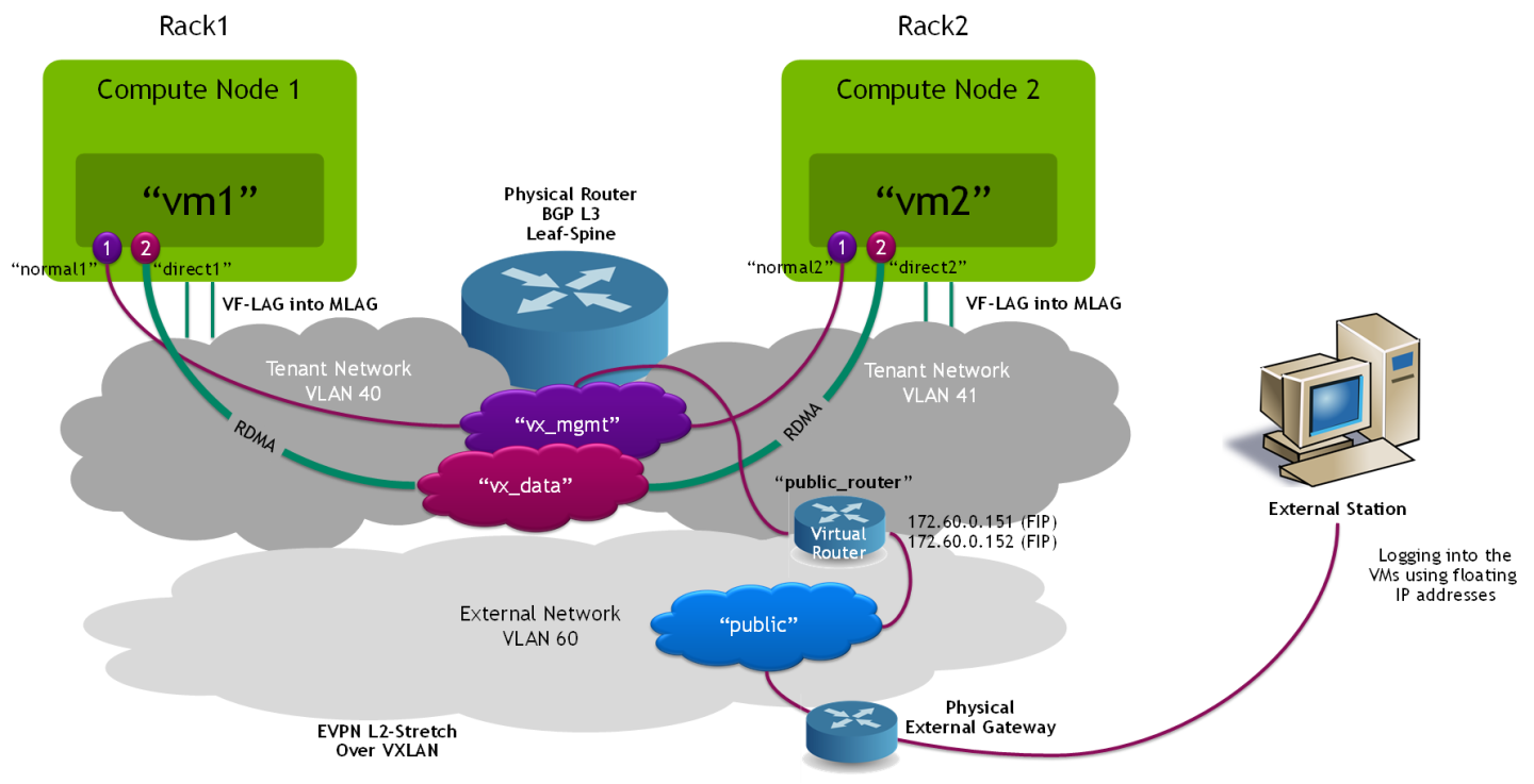
VM Instances
Create a VM instance with a management port and a direct port on the compute node located on the Rack0 L3 network segment:
$ openstack server create --flavor m1.packet --image perf --port normal1 --port direct1 vm1 --availability-zone nova:overcloud-computesriov-rack0-0.localdomain
Create a VM instance with a management port and a direct port on the compute node located on the Rack1 L3 network segment:
$ openstack server create --flavor m1.packet --image perf --port normal2 --port direct2 vm2 --availability-zone nova:overcloud-computesriov-rack1-0.localdomain
Wait until the VM instances status is changed to ACTIVE:
            $ openstack server list
+--------------------------------------+---------+--------+---------------------------------------------------------+-------+--------+
| ID                                   | Name    | Status | Networks                                                | Image | Flavor |
+--------------------------------------+---------+--------+---------------------------------------------------------+-------+--------+
| 000d3e17-9583-4885-aa2d-79c3b5df3cc8 | vm2     | ACTIVE | vx_data=33.33.33.244; vx_mgmt=22.22.22.151              | perf  |        |
| 150013ad-170d-4587-850e-70af692aa74c | vm1     | ACTIVE | vx_data=33.33.33.186; vx_mgmt=22.22.22.59               | perf  |        |
+--------------------------------------+---------+--------+---------------------------------------------------------+-------+--------+
In order to verify that external/public network access is functioning properly, create and assign external floating IP addresses for the VMs:
            $ openstack floating ip create --floating-ip-address 172.60.0.151 public
$ openstack server add floating ip vm1 172.60.0.151
$ openstack floating ip create --floating-ip-address 172.60.0.152 public
$ openstack server add floating ip vm2 172.60.0.152
Appendix
Performance Testing
The performance results listed in this document are indicative and should not be considered as formal performance targets for NVIDIA products.
Note: The tools used in the below tests are included in the VM image built with the perf-tools element, as instructed in previous steps.
iperf TCP Test
On the Transmitter VM, disable XPS (Transmit Packet Steering):
# for i in {0..7}; do echo 0 > /sys/class/net/eth1/queues/tx-$i/xps_cpus; done;
NoteThis step is required to allow packet distribution of the iperf traffic using ConnectX VF-LAG.
Use interface statistic/counters on the Leaf switches' bond interfaces to confirm traffic is distributed by the Transmitter VM to both switches using VF-LAG (Cumulus "net show counters" command).
On the Receiver VM, start multiple iperf3 servers:
            # iperf3 -s -p 5101&
# iperf3 -s -p 5102&
# iperf3 -s -p 5103&
# iperf3 -s -p 5104&
On the Transmitter VM, start multiple iperf3 clients for multi-core parallel streams:
            # iperf3 -c 33.33.33.180 -T s1 -p 5101 -t 15 &
# iperf3 -c 33.33.33.180 -T s2 -p 5102 -t 15 &
# iperf3 -c 33.33.33.180 -T s3 -p 5103 -t 15 &
# iperf3 -c 33.33.33.180 -T s4 -p 5104 -t 15 &
Check the results:
            s1:  - - - - - - - - - - - - - - - - - - - - - - - - -
s1:  [ ID] Interval           Transfer     Bitrate         Retr
s1:  [  5]   0.00-15.00  sec  38.4 GBytes  22.0 Gbits/sec  18239             sender
s1:  [  5]   0.00-15.04  sec  38.4 GBytes  22.0 Gbits/sec                  receiver
s1:
s1:  iperf Done.
s2:  [  5]  14.00-15.00  sec  3.24 GBytes  27.8 Gbits/sec  997   1008 KBytes
s2:  - - - - - - - - - - - - - - - - - - - - - - - - -
s2:  [ ID] Interval           Transfer     Bitrate         Retr
s2:  [  5]   0.00-15.00  sec  45.1 GBytes  25.8 Gbits/sec  22465             sender
s2:  [  5]   0.00-15.04  sec  45.1 GBytes  25.7 Gbits/sec                  receiver
s2:
s2:  iperf Done.
s4:  [  5]  14.00-15.00  sec  2.26 GBytes  19.4 Gbits/sec  1435    443 KBytes
s4:  - - - - - - - - - - - - - - - - - - - - - - - - -
s4:  [ ID] Interval           Transfer     Bitrate         Retr
s4:  [  5]   0.00-15.00  sec  46.5 GBytes  26.6 Gbits/sec  19964             sender
s4:  [  5]   0.00-15.04  sec  46.5 GBytes  26.6 Gbits/sec                  receiver
s4:
s4:  iperf Done.
s3:  [  5]  14.00-15.00  sec  2.70 GBytes  23.2 Gbits/sec  1537    643 KBytes
s3:  - - - - - - - - - - - - - - - - - - - - - - - - -
s3:  [ ID] Interval           Transfer     Bitrate         Retr
s3:  [  5]   0.00-15.00  sec  39.5 GBytes  22.6 Gbits/sec  18447             sender
s3:  [  5]   0.00-15.04  sec  39.5 GBytes  22.6 Gbits/sec                  receiver
s3:
s3:  iperf Done.
NoteThe test results above demonstrate a total of around 100Gbps line rate for IP TCP traffic.
Before proceeding to the next test, stop all iperf servers on the Receiver VM:
            # killall iperf3
iperf3: interrupt - the server has terminated
iperf3: interrupt - the server has terminated
iperf3: interrupt - the server has terminated
iperf3: interrupt - the server has terminated
RoCE Bandwidth Test over the bond
On the Receiver VM, start ib_write_bw server with 2 QPs in order to utilize the VF-LAG infrastructure:
# ib_write_bw -R --report_gbits --qp 2
On the Transmitter VM, start ib_write_bw client with 2 QPs and a duration of 10 seconds:
# ib_write_bw -R --report_gbits --qp 2 -D 10 33.33.33.180
Check the test results:
            ---------------------------------------------------------------------------------------
                    RDMA_Write BW Test
 Dual-port       : OFF          Device         : mlx5_0
 Number of qps   : 2            Transport type : IB
 Connection type : RC           Using SRQ      : OFF
 PCIe relax order: ON
 ibv_wr* API     : ON
 TX depth        : 128
 CQ Moderation   : 1
 Mtu             : 4096[B]
 Link type       : Ethernet
 GID index       : 3
 Max inline data : 0[B]
 rdma_cm QPs     : ON
 Data ex. method : rdma_cm
---------------------------------------------------------------------------------------
 local address: LID 0000 QPN 0x016e PSN 0x3ab6d6
 GID: 00:00:00:00:00:00:00:00:00:00:255:255:33:33:33:173
 local address: LID 0000 QPN 0x016f PSN 0xc9fa3f
 GID: 00:00:00:00:00:00:00:00:00:00:255:255:33:33:33:173
 remote address: LID 0000 QPN 0x016e PSN 0x8d928c
 GID: 00:00:00:00:00:00:00:00:00:00:255:255:33:33:33:180
 remote address: LID 0000 QPN 0x016f PSN 0xc89786
 GID: 00:00:00:00:00:00:00:00:00:00:255:255:33:33:33:180
---------------------------------------------------------------------------------------
 #bytes     #iterations    BW peak[Gb/sec]    BW average[Gb/sec]   MsgRate[Mpps]
 65536      22065492         0.00               192.81             0.367756
---------------------------------------------------------------------------------------
Single-core DPDK packet-rate test over a single port
In this test, we used two VMs - one running the trex traffic generator and the other running the dpdk-testpmd tool.
The traffic generator sends 64 byte packets to the test-pmd tool and the tool sends them back (thus testing the DPDK packet-processing pipeline).
We tested single-core packet processing rate between two VMs using 2 tx and rx queues.
Please note that this test requires using specific versions of DPDK and the VM image kernel and compatibility issues might exist when using the latest releases.
For this test we used a CentOS 7.8 image with kernel 3.10.0-1160.42.2 and DPDK 20.11.
On one VM we activated the dpdk-testpmd utility, this is the command line used to run testpmd (this command displays the MAC address of the port to be used later on with trex as the destination port MAC):
testpmd VM console
# ./dpdk-testpmd -c 0x1ff -n 4 -m 1024 -a 00:05.0 -- --burst=64 --txd=1024 --rxd=1024 --mbcache=512 --rxq=4 --txq=4 --nb-cores=1 --rss-udp --forward-mode=macswap -a -i
Next, we created a second VM with two direct ports (on the vx_data network) and used it for running the trex traffic generator (version 2.82):
We ran the DPDK port setup interactive wizard and used the MAC address of the TestPMD VM collected beforehand:
trex VM console
            # cd /root/trex/v2.82
# ./dpdk_setup_ports.py -i
By default, IP based configuration file will be created. Do you want to use MAC based config? (y/N)y
+----+------+---------+-------------------+----------------------------------------------+------------+----------+----------+
| ID | NUMA |   PCI   |        MAC        |                     Name                     |   Driver   | Linux IF |  Active  |
+====+======+=========+===================+==============================================+============+==========+==========+
| 0  | -1   | 00:03.0 | fa:16:3e:11:3e:64 | Virtio network device                        | virtio-pci | eth0     | *Active* |
+----+------+---------+-------------------+----------------------------------------------+------------+----------+----------+
| 1  | -1   | 00:05.0 | fa:16:3e:cb:a4:82 | ConnectX Family mlx5Gen Virtual Function     | mlx5_core  | eth1     |          |
+----+------+---------+-------------------+----------------------------------------------+------------+----------+----------+
| 2  | -1   | 00:06.0 | fa:16:3e:58:79:e2 | ConnectX Family mlx5Gen Virtual Function     | mlx5_core  | eth2     |          |
+----+------+---------+-------------------+----------------------------------------------+------------+----------+----------+
Please choose an even number of interfaces from the list above, either by ID, PCI or Linux IF
Stateful will use order of interfaces: Client1 Server1 Client2 Server2 etc. for flows.
Stateless can be in any order.
Enter list of interfaces separated by space (for example: 1 3) : 1 2

For interface 1, assuming loopback to its dual interface 2.
Destination MAC is fa:16:3e:58:79:e2. Change it to MAC of DUT? (y/N).y
Please enter a new destination MAC of interface 1: FA:16:3E:32:5C:A4
For interface 2, assuming loopback to its dual interface 1.
Destination MAC is fa:16:3e:cb:a4:82. Change it to MAC of DUT? (y/N).y
Please enter a new destination MAC of interface 2: FA:16:3E:32:5C:A4
Print preview of generated config? (Y/n)
### Config file generated by dpdk_setup_ports.py ###

- version: 2
  interfaces: ['00:05.0', '00:06.0']
  port_info:
      - dest_mac: fa:16:3e:32:5c:a4
        src_mac:  fa:16:3e:cb:a4:82
      - dest_mac: fa:16:3e:32:5c:a4
        src_mac:  fa:16:3e:58:79:e2

  platform:
      master_thread_id: 0
      latency_thread_id: 1
      dual_if:
        - socket: 0
          threads: [2,3,4,5,6,7,8,9]


Save the config to file? (Y/n)y
Default filename is /etc/trex_cfg.yaml
Press ENTER to confirm or enter new file:
Saved to /etc/trex_cfg.yaml.
We create the following UDP packet stream configuration file under the /root/trex/v2.82 directory:
udp_rss.py
            from trex_stl_lib.api import *

class STLS1(object):

    def create_stream (self):

        pkt = Ether()/IP(src="16.0.0.1",dst="48.0.0.1")/UDP(dport=12)/(22*'x')

        vm = STLScVmRaw( [
                                STLVmFlowVar(name="v_port",
                                                min_value=4337,
                                                  max_value=5337,
                                                  size=2, op="inc"),
                                STLVmWrFlowVar(fv_name="v_port",
                                            pkt_offset= "UDP.sport" ),
                                STLVmFixChecksumHw(l3_offset="IP",l4_offset="UDP",l4_type=CTRexVmInsFixHwCs.L4_TYPE_UDP),

                            ]
                        )

        return STLStream(packet = STLPktBuilder(pkt = pkt ,vm = vm ) ,
                                mode = STLTXCont(pps = 8000000) )


    def get_streams (self, direction = 0, **kwargs):
        # create 1 stream
        return [ self.create_stream() ]


# dynamic load - used for trex console or simulator
def register():
    return STLS1()
Next, we ran the TRex application in the background over 8 out of 10 cores:
trex VM console
# nohup ./t-rex-64 --no-ofed-check -i -c 8 &
And finally ran the TRex Console:
trex VM console
            # ./trex-console

Using 'python' as Python interpeter


Connecting to RPC server on localhost:4501                   [SUCCESS]


Connecting to publisher server on localhost:4500             [SUCCESS]


Acquiring ports [0, 1]:                                      [SUCCESS]


Server Info:

Server version:   v2.82 @ STL
Server mode:      Stateless
Server CPU:       8 x AMD EPYC Processor (with IBPB)
Ports count:      2 x 100Gbps @ ConnectX Family mlx5Gen Virtual Function

-=TRex Console v3.0=-

Type 'help' or '?' for supported actions

trex>
In the TRex Console, entered the UI (TUI):
trex VM console
trex>tui
And started a 35MPPS stream using the stream configuration file created in previous steps:
trex VM console
tui>start -f udp_rss.py -m 35mpps -p 0
And these are the measured results on the testpmd VM (~32.5mpps):
testpmd tool console
            testpmd> show port stats all

######################## NIC statistics for port 0 ########################
RX-packets: 486825081 RX-missed: 14768224 RX-bytes: 29209504860
RX-errors: 0
RX-nombuf: 0
TX-packets: 486712558 TX-errors: 0 TX-bytes: 29202753480

Throughput (since last show)
Rx-pps: 32542689 Rx-bps: 15620491128
Tx-pps: 32542685 Tx-bps: 15620488872
############################################################################
Troubleshooting the Nodes in Case Network Is Not Functioning
In case there is a need to debug the overcloud nodes due to issues in the deployment, the only way to connect to them is using an SSH key that is placed in the director node.
Connecting through a BMC console is useless since there is no way to log in to the nodes using a username and a password.
Since the nodes are connected using a single network, there can be a situation in which they are completely inaccessible for troubleshooting in case there is an issue with the YAML files and so forth.
The solution for this is to add the following lines to the env-ovs-dvr.yaml file (under the mentioned sections) that will allow for setting a root password for the nodes so they become accessible from the BMC console:
            resource_registry:
   OS::TripleO::NodeUserData: /usr/share/openstack-tripleo-heat-templates/firstboot/userdata_root_password.yaml

parameter_defaults:
  NodeRootPassword: "******"
The overcloud to e deleted and redeployed in order for the above changes to affect.
Note: this feature and the "Automatic NIC Firmware Provisioning" feature are mutually exclusive and can't be used in parallel as they both use the "NodeUserData" variable!
Note: Make sure to remove the above lines in case of a production cloud as they pose a security hazard
Once the nodes are accessible, an additional helpful step to troubleshoot network issues on the nodes would be to run the following script on the problematic nodes:
# os-net-config -c /etc/os-net-config/config.json -d
This script will try to reconfigure the network and will indicate any relevant issues.
Authors

|
Itai Levy Over the past few years, Itai Levy has worked as a Solutions Architect and member of the NVIDIA Networking “Solutions Labs” team. Itai designs and executes cutting-edge solutions around Cloud Computing, SDN, SDS and Security. His main areas of expertise include NVIDIA BlueField Data Processing Unit (DPU) solutions and accelerated OpenStack/K8s platforms. |

|
Shachar Dor Shachar Dor joined the Solutions Lab team after working more than ten years as a software architect at NVIDIA Networking (previously Mellanox Technologies), where he was responsible for the architecture of network management products and solutions. Shachar's focus is on networking technologies, especially around fabric bring-up, configuration, monitoring, and life-cycle management. Shachar has a strong background in software architecture, design, and programming through his work on multiple projects and technologies also prior to joining the company. |