RDG for Virtualizing GPU-Accelerated HPC and AI Workloads on OpenStack Cloud over InfiniBand Fabric
Created on Mar 10, 2022
Abbreviations and Acronyms
|
Term |
Definition |
Term |
Definition |
|
ACS |
Access Control Services |
MLNX_OFED |
NVIDIA OpenFabrics Enterprise Distribution for Linux (network driver) |
|
AI |
Artificial Intelligence |
OC |
Overcloud |
|
ATS |
Address Translation Services |
OS |
Operating System |
|
BOM |
Bill of Materials |
PKey |
Private Key |
|
CUDA |
Compute Unified Device Architecture |
RDG |
Reference Deployment Guide |
|
DIB |
Disk Image Builder |
RDMA |
Remote Direct Memory Access |
|
DHCP |
Dynamic Host Configuration Protocol |
RDO |
RPM Distribution of OpenStack |
|
GDR |
GPUDirect RDMA |
SDN |
Software Defined Networking |
|
GPU |
Graphics Processing Unit |
SR-IOV |
Single Root Input/Output Virtualization |
|
HA |
High Availability |
TripleO |
OpenStack On OpenStack |
|
HPC |
High Performance Computing |
UFM |
Unified Fabric Manager |
|
IB |
InfiniBand |
VF |
Virtual Function |
|
IPMI |
Intelligent Platform Management Interface |
VLAN |
Virtual LAN |
|
IPoIB |
IP over InfiniBand |
VM |
Virtual Machine |
References
Introduction
The OpenStack cloud operating system includes support for virtualization services with SR-IOV networking and GPUs over an InfiniBand fabric. This allows a multi-tenant, secure and accelerated cloud deployment that provides best-in-class performance for HPC and AI workloads.
The following Reference Deployment Guide (RDG) demonstrates a complete deployment of OpenStack Cloud for virtualized HPC/AI workloads accelerated by NVIDIA® GPUs, adapters, and NVIDIA Quantum InfiniBand fabric. The RDG covers a single-rack reference deployment that could easily scale up to multi-rack solution.
This RDG includes a solution design, scale considerations, hardware BOM (Bill of Materials) and the complete list of steps to both provision cloud tenant virtual instances located on distributed compute nodes over an NVIDIA Quantum InfiniBand fabric and perform NVIDIA GPUDirect®-RDMA infrastructure bandwidth testing.
The following solution is based on OpenStack RDO ("Wallaby" release) as a cloud platform with integrated InfiniBand support deployed using TripleO software.
Solution Architecture
Key Components and Technologies
NVIDIA A100 Tensor Core GPU delivers unprecedented acceleration at every scale to power the world’s highest-performing elastic data centers for AI, data analytics, and HPC. Powered by the NVIDIA Ampere Architecture, A100 is the engine of the NVIDIA data center platform. A100 provides up to 20X higher performance over the prior generation and can be partitioned into seven GPU instances to dynamically adjust to shifting demands.
ConnectX®-6 InfiniBand adapter cards are a key element in the NVIDIA Quantum InfiniBand platform. ConnectX-6 provides up to two ports of 200Gb/s InfiniBand connectivity with extremely low latency, high message rate, smart offloads, and NVIDIA In-Network Computing acceleration that improve performance and scalability.
The NVIDIA Quantum InfiniBand switches provide high-bandwidth performance, low power, and scalability. NVIDIA Quantum switches optimize data center connectivity with advanced routing and congestion avoidance capabilities.
The LinkX® product family of cables and transceivers provides complete connectivity matrix for InfiniBand data center infrastructures.
NVIDIA® UFM® (Unified Fabric Manager) platforms revolutionize data center networking management by combining enhanced, real-time network telemetry with AI-powered cyber intelligence and analytics to support scale-out InfiniBand data centers.
OpenStack is the most widely deployed open-source cloud software in the world. As a cloud operating system, it controls large pools of compute, storage, and networking resources throughout a datacenter, all managed and provisioned through APIs with common authentication mechanisms. Beyond standard infrastructure-as-a-service (Iaas) functionality, additional components provide orchestration, fault management and service management among other services, to ensure high availability of user applications.
RPM Distribution of OpenStack (RDO) is a freely available community-supported distribution of OpenStack originated by Red Hat. RDO runs on CentOS, Red Hat Enterprise Linux (RHEL) and Fedora, and makes the latest OpenStack development release available for use.
Logical Design
The following is an illustration of the solution's logical design.

Single 200Gb/s InfiniBand fabric is used for both tenant and OpenStack control networks.
Neutron components (api/dhcp/l3) include the required code to support InfiniBand on the Controller node.
Network Design
Network Topology
The following is an illustration of the solution's fabric topology:

Reference Architecture Scale
Initial Setup for a One Switch Solution:
Single rack
1 × NVIDIA Quantum QM8700 200G InfiniBand Switch
1 × Undercloud Node
3 × Controller Nodes
2 × Compute Nodes
1 × UFM Fabric Management Node
1 × 1GbE Switch (for multiple 1GbE networks isolated with VLANs)
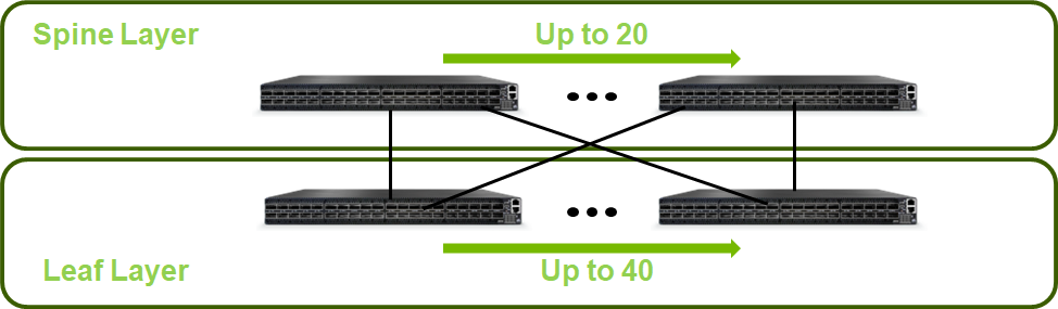
Scaled Setup for a Two-Layer Fat-Tree Topology:
This deployment scenario scales up to 20 Spine switches and 40 Leaf switches and supports up to 800 servers.
NoteScale considerations refer to high speed InfiniBand fabric only and do not cover provisioning, IPMI and External networks.
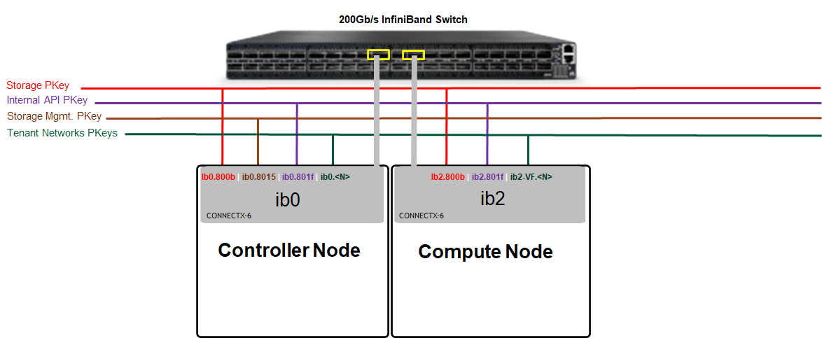
Host Design
Tenant Isolation
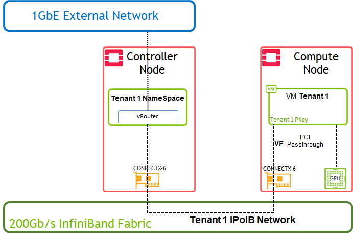
The following is an illustration of the solution's host design.

PKey is used to isolate the Bare Metal instances traffic on the tenant network they belong to.
Tenant NameSpaces include DHCP server / vRouter (L3 Agent) with IPoIB support. It is configured with a PKey to isolate the traffic on the tenant network they belong to.
Application Logical Design

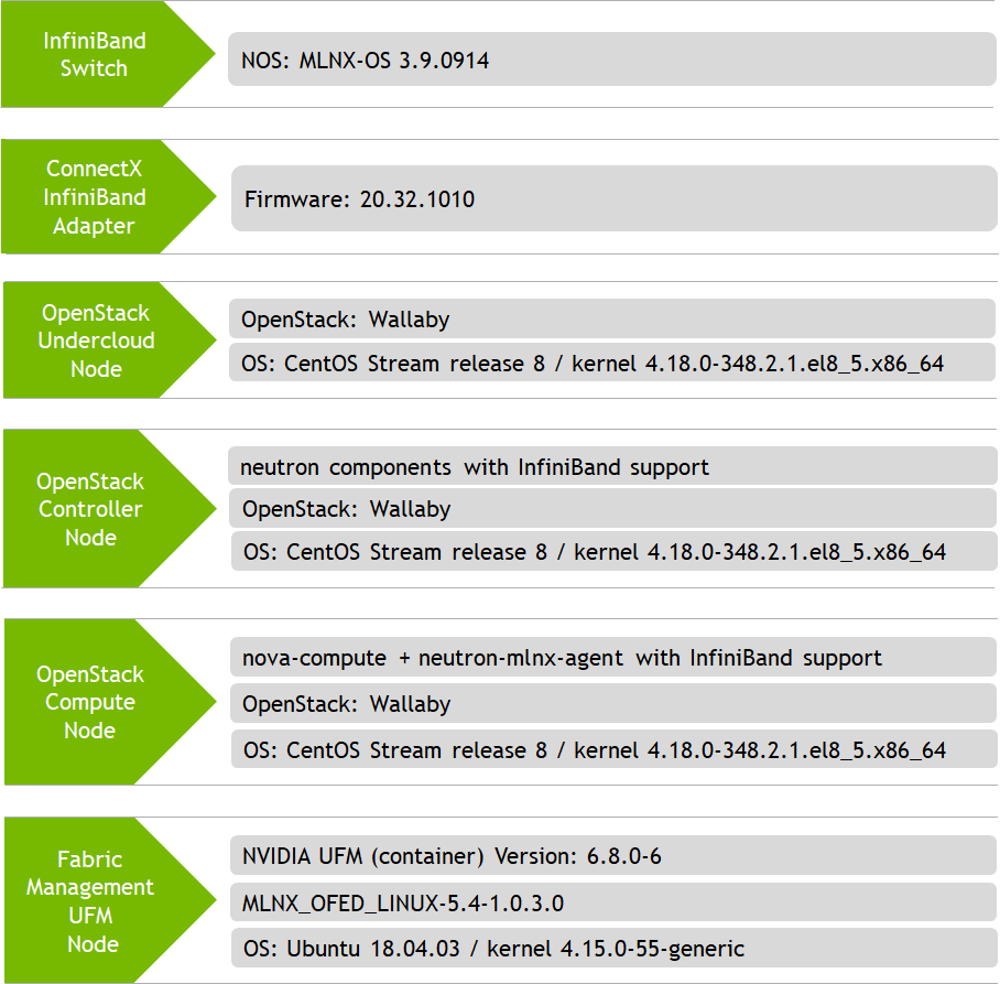
Software Stack Components
Bill of Materials (BOM)
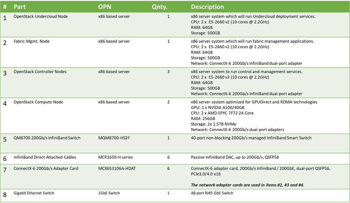
The preceding BoM refers to 1 × Rack based reference architecture.
Solution Configuration and Deployment
Physical Wiring
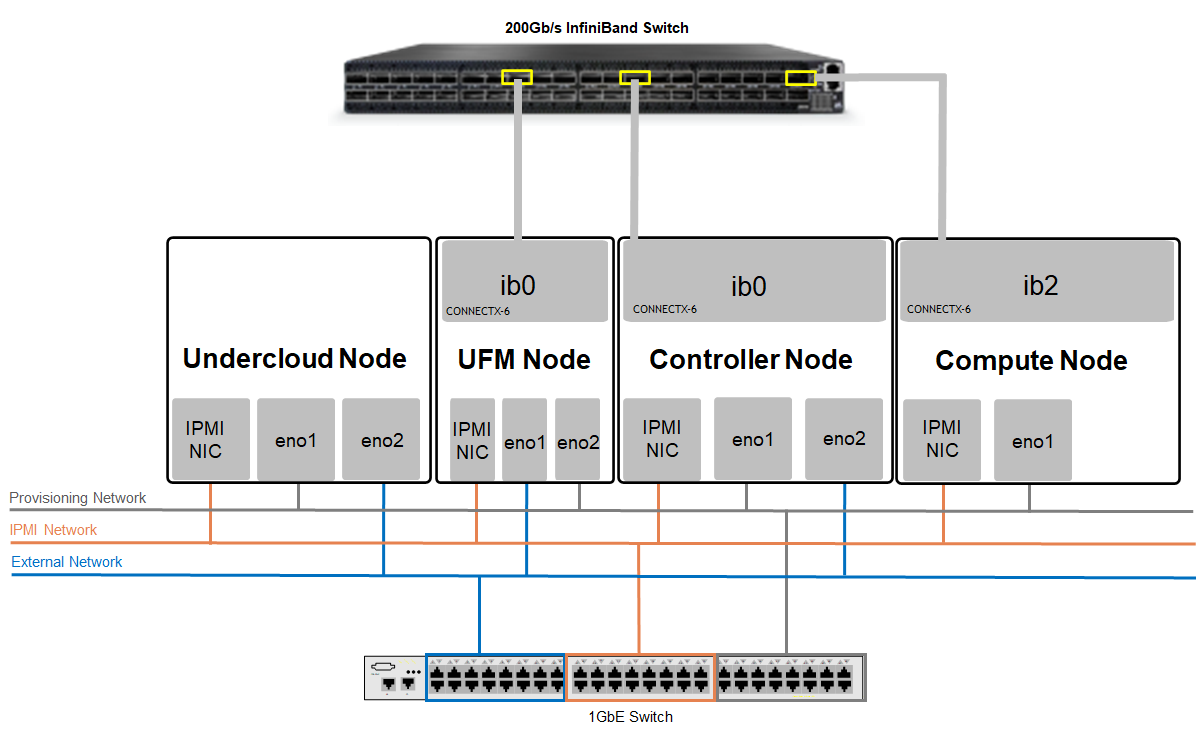
When using a dual-port InfiniBand host channel adapter (HCA), only the first port should be wired to the fabric.
From the OS perspective, the network "ib" device will be used for IPoIB traffic.A single 1GbE Switch was used in this case for multiple 1GbE networks isolated with VLANs.
The UFM Node is connected to the External network to pull the UFM application container from the Internet. It is also possible to use local images without Internet connectivity.
Connect all nodes to the IPMI network.
Connect the IB Switch Mgmt. port to the OpenStack Provisioning network and allocate an IP address outside of the Overcloud nodes range.
Connect the UFM Node to OpenStack Provisioning network and allocate an IP address outside of the Overcloud nodes range.
Connect the UFM Node and the Overcloud nodes (Controller / Compute) to the IB Fabric.
Connect the OpenStack Undercloud and Overcloud nodes to the OpenStack Provisioning network.
Connect the Undercloud, Controllers, and UFM nodes to the External (Public) network.
IPoIB Fabric Configuration
|
Network Name |
Network Details |
PKey ID |
|
Storage |
172.16.0.0 / 24 |
800b |
|
Storage_Mgmt |
172.17.0.0 / 24 |
8015 |
|
Internal API |
172.18.0.0 / 24 |
801f |
|
Tenant VLAN <N> |
Created by Tenant |
<Hex_N> |
In Ethernet OpenStack deployments, VLANs can be used for tenant isolation. With InfiniBand, Partition Keys (PKeys) are used to gain tenant isolation.
Tenant network VLAN ID "N" is mapped to tenant PKey "0x<Hex_N>". In this RDG we use tenant VLAN ID 101 which is converted to PKey 0x65.
Host Configuration
Prerequisites
Hardware specifications are identical for servers with the same role (Controller Nodes/Compute Nodes, and so forth.).
ConnectX-6 adapters configuration:
Controller / Fabric Management Nodes
Latest Firmware
Ports are set to operate in InfiniBand mode (LINK_TYPE_P1 Firmware parameter is set to IB)
Compute Nodes
Latest Firmware
Ports are set to operate in InfiniBand mode (LINK_TYPE_P1 Firmware parameter is set to IB)
SRIOV_EN firmware parameter is set to True
NUM_OF_VFS firmware parameter is set to a value matching the number of Virtual Functions used in OpenStack compute node cloud configuration files
ADVANCED_PCI_SETTINGS firmware parameter is set to True and MAX_ACC_OUT_READ Firmware parameter is set to a value of 44 for optimized bandwidth test results.
ATS_ENABLED firmware parameter is set to True - for GPUDirect RDMA usage in Virtual Machines context.
BIOS Configuration:
Controller Nodes
PXE boot is set in server boot order
Compute Nodes
Virtualization and SR-IOV enabled
PXE boot is set in server boot order
ACS enabled - for GPUDirect RDMA usage in Virtual Machine
NVIDIA Firmware Tools (MFT) can be used for adapter firmware settings.
Fabric Management Node (UFM) Installation
The "Fabric Management" is a Linux-based host running UFM Enterprise application container.
In this article, a single Fabric Management node is deployed. High Availability deployment is possible, however, not covered.
For the UFM Enterprise User Manual refer to this link.
For the UFM Enterprise Docker Container Installation Guide refer to this link.
Using the NVIDIA UFM Enterprise Software requires a license. Please contact NVIDIA Networking Support.

Fabric Management Node OS
Install the OS on the Fabric Mgmt Node. (In this solution we have used Ubuntu 18.04 OS).
Install the NVIDIA MLNX_OFED network drivers. For further information refer to this link.
Install and enable Docker service—Ubuntu Docker Installation.
Use the "ibstat" command to make sure that the Fabric Management Node is connected to the InfiniBand Fabric, and the link is up.
Make sure that the Fabric Management Node is connected to the OpenStack provisioning network and allocate an IP Address outside of the Overcloud nodes range. In our example we have assigned IP 192.168.24.200 to this node.
Set a dummy IP address on the InfiniBand ib0 interface and make sure it is in the "up" state. This step is a prerequisite for UFM application installation.
Noteib0 is the default fabric interface used by the UFM installer. If you have connected ib1 to the InfiniBand fabric, make sure to specify the interface during UFM installer execution.
Make sure that External access is available as it will be used to pull the UFM application container from the Internet. It is also possible to use local images without Internet connectivity.
UFM Enterprise Application Container
Additional information about UFM Container installation is available here.
Create a host directory to store the UFM application configuration.
# mkdir -p /var/ufm_files/
Create a host directory to store the UFM application license, and place the license there.
# mkdir -p /home/ubuntu/UFM_lic/
Make sure that Internet access is available and pull the UFM Enterprise Installer image from the Docker hub repository.
# docker pull mellanox/ufm-enterprise-installer:latest
Run the Installer application container with the local directory mapped, and verify it is up.
NoteFor all installer options and default values, use the following command: "docker run --rm mellanox/ufm-enterprise-installer:latest -h"
The Installer container will bring up a UFM Enterprise application container named "ufm" and will terminate.
            # docker run -it --name=ufm_installer --rm \
-v /var/run/docker.sock:/var/run/docker.sock \
-v /var/ufm_files/:/installation/ufm_files/ \
-v /home/ubuntu/UFM_lic/:/installation/ufm_licenses/ \
mellanox/ufm-enterprise-installer:latest
            Deployment Mode [install/upgrade]:   install
UFM Mode [SA/HA]:                    SA
UFM Enterprise Image:                mellanox/ufm-enterprise:latest
UFM Files Path:                      /var/ufm_files/
UFM License Path:                    /home/ubuntu/UFM_lic/
Fabric Interface:                    ib0
Management Interface:                eth0
Loading UFM Enterprise Image...
latest: Pulling from mellanox/ufm-enterprise
2d473b07cdd5: Pull complete
239fbdbd6064: Pull complete
a25becc1a642: Pull complete
Digest: sha256:05e5341c9edaff55450841852e1657fa4f032d0f29898f5b978663d404ab9470
Status: Downloaded newer image for mellanox/ufm-enterprise:latest
docker.io/mellanox/ufm-enterprise:latest
Creating UFM Enterprise Container...
6efbfd1142b7088533474449e66afb1ca55d5c4838cfd0776213f00f2ad6ba46
UFM Container Created
Copying UFM Configuration Files...
Copying License File...
ufm
[*] Starting UFM Container
ufm
UFM Container started. You can check UFM status by running:
docker exec -it ufm /etc/init.d/ufmd status
============================================================================================
   UFM container installation finished successfully
============================================================================================
Verify that the UFM Enterprise application container is up and the UFM service is running.
            # docker ps -a
CONTAINER ID   IMAGE                            COMMAND                  CREATED         STATUS         PORTS     NAMES
6efbfd1142b7   mellanox/ufm-enterprise:latest   "sh /usr/sbin/docker…"   7 minutes ago   Up 7 minutes             ufm

# docker exec -it ufm /etc/init.d/ufmd status
ufmd status
ufmd (pid 622) is running...
Connect from a client on the External or the Provisioning networks to the UFM WebUI. Use the following URL:
NoteDefault Login Credentials: admin/123456
https://192.168.24.200/ufm/
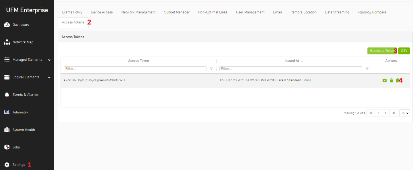
Generate UFM API Access Token and copy it for later usage.
NoteThe token will be used in the OpenStack Overcloud deployment file: neutron-ml2-mlnx-sdn-vm.yaml
OpenStack Undercloud Node Preparation and Installation
The following solution is using TripleO for RDO OpenStack Deployment.
Perform the Undercloud Installation procedure described here up to the "Prepare the configuration file" section. The following components are used:
CentOS Stream release 8 OS with 100GB root partition
"Wallaby" OpenStack Release TripleIO repositories
$ sudo -E tripleo-repos -b wallaby current
Undercloud configuration file "undercloud.conf"
undercloud.conf
            [DEFAULT]
undercloud_hostname = rdo-director.localdomain
local_ip = 192.168.24.1/24
network_gateway = 192.168.24.1
undercloud_public_host = 192.168.24.2
undercloud_admin_host = 192.168.24.3
undercloud_nameservers = 10.7.77.192,10.7.77.135
undercloud_ntp_servers = 10.211.0.134,10.211.0.124
subnets = ctlplane-subnet
local_subnet = ctlplane-subnet
generate_service_certificate = True
certificate_generation_ca = local
local_interface = eno1
inspection_interface = br-ctlplane
undercloud_debug = true
enable_tempest = false
enable_telemetry = false
enable_validations = true
enable_novajoin = false
clean_nodes = true
container_images_file = /home/stack/containers-prepare-parameter-ib-vm.yaml

[auth]

[ctlplane-subnet]
cidr = 192.168.24.0/24
dhcp_start = 192.168.24.5
dhcp_end = 192.168.24.30
inspection_iprange = 192.168.24.100,192.168.24.120
gateway = 192.168.24.1
masquerade = true
Create the following Container Image Preparation configuration file "containers-prepare-parameter-ib-vm.yaml" referred to in "undercloud.conf" and place it under /home/stack/ directory.
containers-prepare-parameter-ib-vm.yaml
            #global
ContainerImagePrepare:
  - push_destination: 192.168.24.1:8787
    set:
      name_prefix: openstack-
      name_suffix: ''
      namespace: docker.io/tripleowallaby
      neutron_driver: null
      tag: current-tripleo
    tag_from_label: rdo_version
# nova and neutron components
  - push_destination: "192.168.24.1:8787"
    set:
      tag: "current-tripleo"
      namespace: "docker.io/tripleowallaby"
      name_prefix: "openstack-"
      name_suffix: ""
      rhel_containers: "false"
    includes:
    - nova-compute
    - neutron-server
    - neutron-dhcp-agent
    - neutron-l3-agent
    modify_role: tripleo-modify-image
    modify_append_tag: "-updated"
    modify_vars:
      tasks_from: yum_install.yml
      yum_repos_dir_path: /etc/yum.repos.d
      yum_packages: ['python3-networking-mlnx']

# mlnx-agent
  - push_destination: "192.168.24.1:8787"
    set:
      tag: "current-tripleo"
      namespace: "docker.io/tripleowallaby"
      name_prefix: "openstack"
      name_suffix: ""
      rhel_containers: "false"
    includes:
    - neutron-mlnx-agent
Complete the Undercloud installation as a stack user.
            # sudo chown stack -R /home/stack
# su - stack
$ openstack undercloud install
Build the Overcloud Images based on CentOS 8 and Wallaby release components. The full procedure is described here.
            $ su - stack
$ mkdir /home/stack/images
$ cd /home/stack/images
$ export DIB_RELEASE=8-stream
$ export DIB_YUM_REPO_CONF="/etc/yum.repos.d/*"
$ export STABLE_RELEASE="wallaby"

$ openstack overcloud image build
Upload the Overcloud images into the image store as stack user.
            # su - stack
$ source ~/stackrc
$ cd /home/stack/images/
$ openstack overcloud image upload
Prepare the overcloud bare metal nodes inventory file " instackenv.json" with the nodes IPMI information. Our inventory includes 3 Controller nodes and 2 Compute nodes. Make sure to update the file with the IPMI server addresses and credentials.
instackenv.json
            {
    "nodes": [
        {
            "name": "controller-1",
            "pm_type":"ipmi",
            "pm_user":"rcon",
            "pm_password":"******",
            "pm_addr":"172.16.1.1"
        },
        {
            "name": "controller-2",
            "pm_type":"ipmi",
            "pm_user":"rcon",
            "pm_password":"******",
            "pm_addr":"172.16.1.2"
        },
        {
            "name": "controller-3",
            "pm_type":"ipmi",
            "pm_user":"rcon",
            "pm_password":"******",
            "pm_addr":"172.16.1.3"
        },
        {
            "name": "compute-1",
            "pm_type":"ipmi",
            "pm_user":"rcon",
            "pm_password":"******",
            "pm_addr":"172.16.1.4"
        },
        {
            "name": "compute-2",
            "pm_type":"ipmi",
            "pm_user":"rcon",
            "pm_password":"******",
            "pm_addr":"172.16.1.5"
        }
    ]
}
Import the overcloud bare metal nodes inventory and wait until all nodes are listed in "manageable" state.
            $ openstack overcloud node import /home/stack/instackenv.json
$ openstack baremetal node list
+--------------------------------------+--------------+---------------+-------------+--------------------+-------------+
| UUID                                 | Name         | Instance UUID | Power State | Provisioning State | Maintenance |
+--------------------------------------+--------------+---------------+-------------+--------------------+-------------+
| a1b7fca7-a4e5-493e-bfbb-783bc00deb38 | controller-1 | None          | power off   | manageable         | False       |
| a9de9f59-309d-49cf-b059-0c79a9e106b9 | controller-2 | None          | power off   | manageable         | False       |
| 1117a8ac-2a5a-47d0-b3b9-0a43e02a3022 | controller-3 | None          | power off   | manageable         | False       |
| 1fa87c5a-897a-42db-975a-44c6b7c3af5b | compute-1    | None          | power off   | manageable         | False       |
| c04319a0-8298-4ab6-9c83-ad45de97723f | compute-2    | None          | power off   | manageable         | False       |
+--------------------------------------+--------------+---------------+-------------+--------------------+-------------+
OpenStack Overcloud Introspection and IB Infrastructure Configuration
On the Undercloud node, start the Overcloud nodes Introspection procedure.
            $ openstack overcloud node introspect --all-manageable
$ openstack overcloud node configure --all-manageable --instance-boot-option local --root-device largest --boot-mode bios
$ openstack overcloud node provide --all-manageable
$ openstack baremetal node list
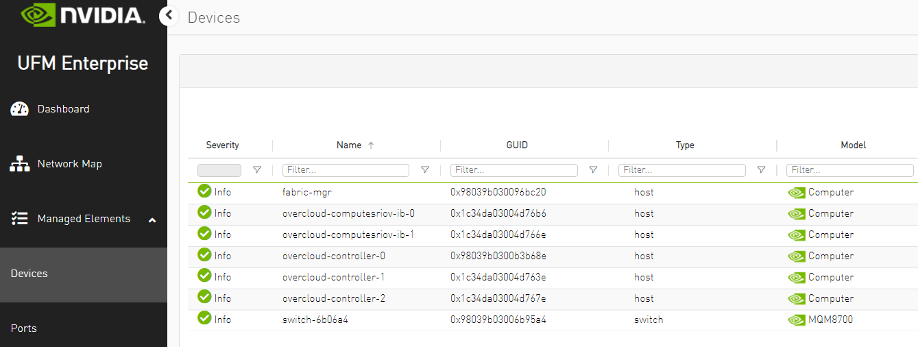
NoteDuring the Introspection phase, the Overcloud InfiniBand devices will appear in the UFM Web UI. Use the time that setup devices are discovered to complete the creation of control PKeys as described in the next step. If Introspection is completed before you are able to set the PKey configuration, and InfiniBand devices no longer appear in the UFM, repeat the Introspection to complete the PKey configuration steps.
"--boot-mode bios" is used to deploy Overcloud servers with Legacy BIOS mode. If the nodes are configured with UEFI BIOS, this flag can be omitted.
While setup devices are discovered, log into UFM Web UI and configure the control PKeys:
Network Name
PKey ID
Storage
0x0b
Storage_Mgmt
0x15
Internal API
0x1f
Network Name
PKey ID
Storage
0x0b
Storage_Mgmt
0x15
Internal API
0x1f
NoteThe control PKeys in UFM are correlated with the control PKeys that will be configured on OpenStack Overcloud nodes during the cloud deployment
The procedure includes the following steps:
Verify setup devices are discovered.
Create PKey with Hex ID.
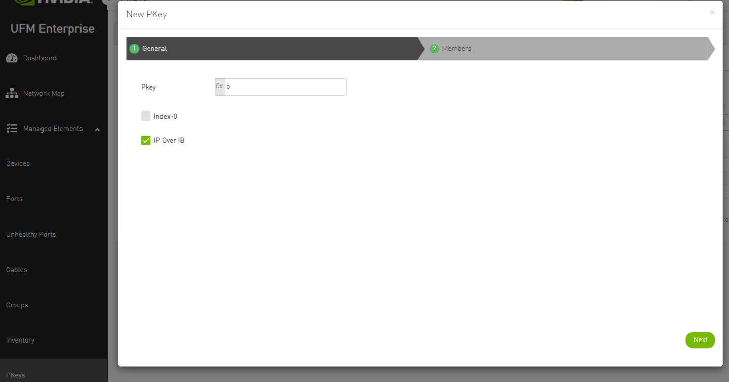
Add the Overcloud nodes GUIDs as a member in the control PKey.
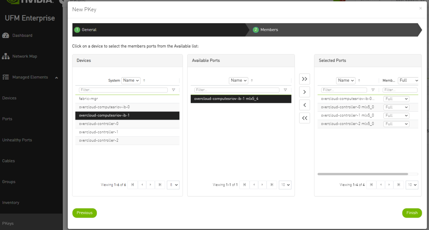
Repeat the steps for every Control PKey.
Proceed to the following Overcloud Deployment steps only after all control PKeys are defined with all Overcloud nodes ports GUID as members.
OpenStack Overcloud Deployment
Download to the Undercloud node and extract the cloud deployment configuration files used for the reference solution in this article: doc-30608172-RDG-Config-Files.zip
Modify the deployment files according to your needs and configuration and place it under the /home/stack/templates/IB/VM directory. The following files were used to deploy the cloud described in this article:
network_data_ib_vm.yaml
vip-data-ib-vm.yaml
roles_data_ib_vm.yaml
containers-prepare-parameter-ib-vm.yaml
node-info-ib-vm.yaml
controller-ib-vm-nics.j2 (referred in node-info-ib-bm.yaml)
compute-ib-vm-nics.j2
NoteMake sure the relevant InfiniBand interface name is used. In this configuration file it is "ib2".
OpenStack command "openstack baremetal introspection interface list <node name>" can be used to locate the relevant interface name.
neutron-ml2-mlnx-sdn-vm.yaml
NoteThis configuration file contains the connection details of the Fabric Management Node.
Use the UFM API Token collected in previous steps for the MlnxSDNToken parameter.
Use the UFM Node IP on the OpenStack Provisioning network for the MlnxSDNUrl parameter (192.168.24.200).
MlnxSDNUsername and MlnxSDNPassword should be included with an empty value.
ib-env-vm.yaml
NoteThis environment file contains the following settings:
Overcloud nodes Time and DNS settings.
NVIDIA A100 alias for GPU PCI passthrough.
Compute nodes CPU partitioning and isolation adjusted to Numa topology.
Nova PCI passthrough settings adjusted to SRIOV InfiniBand Virtual Functions and GPU. Make sure the relevant InfiniBand interface name is used.
Multi-interface physnet mapping: "datacentre" physical network is mapped to the Open vSwitch driver (Ethernet fabric) while "ibnet" physical network is mapped to the IPoIB driver (InfiniBand fabric).
In order to limit the IB-SDN control to the InfiniBand physical network only, explicitly specify the InfiniBand physical network name (for example "physical_networks=ibnet") under the [sdn] section in ml2_conf.ini file on the Controller nodes after the cloud is deployed and restart the neutron_api service container and UFM application.
As "stack" user, issue the deploy command to start Overcloud deployment with the prepared configuration files.
Deploy Command
            $ openstack overcloud deploy --templates /usr/share/openstack-tripleo-heat-templates \
  --networks-file /home/stack/templates/IB/VM/network_data_ib_vm.yaml \
  --vip-file /home/stack/templates/IB/VM/vip-data-ib-vm.yaml \
  --baremetal-deployment /home/stack/templates/IB/VM/node-info-ib-vm.yaml \
  --network-config \
  -r /home/stack/templates/IB/VM/roles_data_ib_vm.yaml \
  -e /home/stack/templates/IB/VM/containers-prepare-parameter-ib-vm.yaml \
  -e /usr/share/openstack-tripleo-heat-templates/environments/podman.yaml \
  -e /usr/share/openstack-tripleo-heat-templates/environments/services/neutron-ovs.yaml \
  -e /usr/share/openstack-tripleo-heat-templates/environments/services/neutron-mlnx-agent.yaml \
  -e /home/stack/templates/IB/VM/neutron-ml2-mlnx-sdn-vm.yaml \
  -e /home/stack/templates/IB/VM/ib-env-vm.yaml \
  --validation-warnings-fatal \
  -e /usr/share/openstack-tripleo-heat-templates/environments/disable-telemetry.yaml
OpenStack Cloud Guest Images Creation
Run the following build command on a CentOS Stream 8 Disk Image Builder machine in order to create a CentOS 8 Stream Guest OS image with IPoIB support:
            # export DIB_RELEASE=8-stream
# disk-image-create vm dhcp-all-interfaces cloud-init-datasources cloud-init-config cloud-init-net-conf-disabled rdma-core dracut-regenerate growroot epel centos -o /home/stack/images/centos8-stream
NoteThe command might require setting proper environment variables. For more information regarding image creation and customization procedure refer to: How-to: Create OpenStack Cloud Image with NVIDIA GPU and Network Drivers
The outcome of the command will be a centos8-stream.qcow image file located under /home/stack/images/ directory.
In the example described in this document, the Guest OS image is customized with "cloud-init" element for access credentials, "cloud-init-net-conf-disabled" element for NetworkManager interface auto configuration and "rdma-core" element for rdma-core package installation. Refer to the How-to article for further information regarding the elements.
The Undercloud node can be used as a Disk Image Builder (DIB) machine.
For CentOS 7 Guest OS image with IPoIB deployment support, use "mofed" and "dhclient-hw" DIB elements as described in the How-to article.
Copy the Guest OS image prepared in the previous section to the Undercloud Node and upload it to the Overcloud image store:
            $ source overcloudrc
$ openstack image create centos8-stream --public --disk-format qcow2 --container-format bare --file /home/stack/images/centos8-stream.qcow2
$ openstack image list
To build a CentOS 8 Stream Guest OS image with IPoIB support and GPUDirect RDMA stack, use the following command:
            # export DIB_RELEASE=8-stream
# disk-image-create vm dhcp-all-interfaces cloud-init-datasources cloud-init-config cloud-init-net-conf-disabled dracut-regenerate growroot epel mofed cuda gpudirect-bench centos -o centos8-stream-gdr
NoteIn the following example, the Guest OS image is customized with elements required for GPUDirect RDMA support in addition to IPoIB such as "mofed" for NVIDIA network drivers, "cuda" for NVIDIA GPU CUDA drivers and "gpudirect-bench" for testing tools. Refer to the How-to article for further information regarding the elements.
The command requires additional environment variables. For the full procedure of image creation with GPUDirect support refer the How-to article.
As instructed in this article, this command must be executed on a build host with CUDA-Enabled NVIDIA GPU device.
NoteMLNX_OFED v5.6 and up must be used for the GPUDirect RDMA benchmark test described in this article
Copy the Guest OS image prepared in the previous section to the Undercloud Node and upload it to the Overcloud image store:
            $ source overcloudrc
$ openstack image create centos8-stream-gdr --public --disk-format qcow2 --container-format bare --file /home/stack/images/centos8-stream-gdr.qcow2
Cloud Tenant Virtual Instances Provisioning
Perform the following steps to create tenant virtual guest instances with dedicated GPU and SR-IOV VFs located on distributed Compute nodes and connected over IPoIB for HPC / AI workloads.
Create a flavor and set an alias for GPU allocation.
NoteThe flavor alias name should match the GPU alias name used in the Compute node cloud configuration file during overcloud deployment phase
            $ openstack flavor create m1.gpu --ram 8192 --disk 40 --vcpus 8
$ openstack flavor set m1.gpu --property hw:cpu_policy=dedicated
$ openstack flavor set m1.gpu --property "pci_passthrough:alias"="a100:1"
Create a tenant network and a subnet.
NoteUpon creation of the tenant network, Neutron will call the UFM to create a tenant PKey, matching the specified VLAN ID and add the Controller nodes ports GUID and the VMs virtual ports GUID into it.
The VLAN ID is converted into a unique IB PKey (VLAN ID 101 → PKey ID 0x65 in this case) and configured on the fabric by the Fabric Management (Mgmt) Node (UFM) to provide tenant isolation.
Map the network to the "ibnet" physical network (InfiniBand fabric).
            $ openstack network create ib_tenant_net --provider-physical-network ibnet --provider-network-type vlan --provider-segment 101 --share
$ openstack subnet create ib_subnet --dhcp --network ib_tenant_net --subnet-range 11.11.11.0/24 --dns-nameserver 8.8.8.8
Create two direct SR-IOV ports on the provisioned network.
            $ openstack port create direct1 --vnic-type=direct --network ib_tenant_net
$ openstack port create direct2 --vnic-type=direct --network ib_tenant_net
Adjust the Controller nodes to support IPoIB DHCP requests from CentOS 8 guest instances:
NoteBy default, IPoIB DHCP requests from Centos7 guest instances will be answered, while IPoIB DHCP requests sent by CentOS 8 guest instances will be ignored.
After executing this procedure CentOS 8 guest instances IPoIB DHCP requests are answered while CentOS 7 guest instances require dhclient.conf modification.
It is possible to customize CentOS 7 guest images with a "dhclient-hw" element as described in How-to: Create OpenStack Cloud Image with NVIDIA GPU and Network Drivers to include the required dhclient.conf modification.
SSH into ALL controller nodes.
Append the following section to /var/lib/config-data/puppet-generated/neutron/etc/neutron/plugins/ml2/ml2_conf.ini file.
            [mlnx]
client_id_hardware=True
Restart Neutron server container.
# podman restart neutron_api
Create an instance on the first compute node with one direct SR-IOV port and A100 GPU.
$ openstack server create --flavor m1.gpu --image centos8-stream-gdr --port direct1 vm1_gpu --availability-zone nova:overcloud-computesriov-ib-0.localdomain
Create another instance on the second compute node with a direct SR-IOV port and A100 GPU.
$ openstack server create --flavor m1.gpu --image centos8-stream-gdr --port direct2 vm2_gpu --availability-zone nova:overcloud-computesriov-ib-1.localdomain
Verify that the virtual tenant instances are up and Active.
            $ openstack server list  +--------------------------------------+---------+--------+----------------------------+--------------------------------------+--------+
| ID                                   | Name    | Status | Networks                   | Image                                | Flavor |
+--------------------------------------+---------+--------+----------------------------+--------------------------------------+--------+
| 7097f8a9-c9bb-4447-b61b-ddb4bdbfd032 | vm1_gpu | ACTIVE | ib_tenant_net=11.11.11.250 | centos8-stream-gdr                   |        |
| b7a3c008-79e3-4eab-9322-68efe19ceee3 | vm2_gpu | ACTIVE | ib_tenant_net=11.11.11.175 | centos8-stream-gdr                   |        |
+--------------------------------------+---------+--------+----------------------------+--------------------------------------+--------+
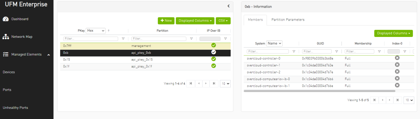
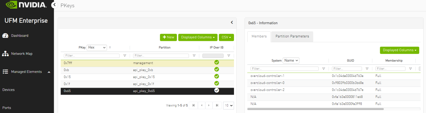
Log into the UFM WebUI and verify that a tenant PKey has been provisioned automatically per the created tenant network and that relevant GUIDs have been added as members.
NoteAs seen in the following image, VLAN ID 101 was mapped to PKey ID 0x65 and the GUIDs of the controllers and VMs assigned ports were added to the PKey as a members.
Connect to one of the tenant VMs and check IPoIB connectivity to the VM on the remote Compute node.
NoteDHCP server namespace on the Controller Node can be used to gain SSH access to the VM.
            [root@overcloud-controller-0 heat-admin]# ip netns
qdhcp-2162790f-e358-4e09-8f59-25e3021396df (id: 0)
[root@overcloud-controller-0 heat-admin]# ip netns exec qdhcp-2162790f-e358-4e09-8f59-25e3021396df ssh stack@11.11.11.250
The authenticity of host '11.11.11.250 (11.11.11.250)' can't be established.
ECDSA key fingerprint is SHA256:l1TUAy2fptWabked17RUL6X8uE+EfzCRByjUAjmc1Uk.
Are you sure you want to continue connecting (yes/no/[fingerprint])? yes
Warning: Permanently added '11.11.11.250' (ECDSA) to the list of known hosts.
stack@11.11.11.250's password:
Activate the web console with: systemctl enable --now cockpit.socket

[stack@host-11-11-11-250 ~]$ sudo su
[root@host-11-11-11-250 stack]# ping 11.11.11.175
PING 11.11.11.175 (11.11.11.175) 56(84) bytes of data.
64 bytes from 11.11.11.175: icmp_seq=1 ttl=64 time=13.10 ms
64 bytes from 11.11.11.175: icmp_seq=2 ttl=64 time=0.139 ms
64 bytes from 11.11.11.175: icmp_seq=3 ttl=64 time=0.068 ms
64 bytes from 11.11.11.175: icmp_seq=4 ttl=64 time=0.069 ms
^C
--- 11.11.11.175 ping statistics ---
4 packets transmitted, 4 received, 0% packet loss, time 3057ms
rtt min/avg/max/mdev = 0.068/3.557/13.954/6.002 ms
Instance External Access using vRouter and Floating IP
Create an external Ethernet provider network with a gateway leading to the public network.
            $ openstack network create public --provider-physical-network datacentre --provider-network-type flat --external
$ openstack subnet create public_subnet --no-dhcp --network public --subnet-range 10.7.208.0/24 --allocation-pool start=10.7.208.65,end=10.7.208.94 --gateway 10.7.208.1
Create a vRouter and attach to it both the external and the previously created IPoIB tenant networks, to allow external connectivity for all virtual instances on the tenant network.
            $ openstack router create public_router --no-ha
$ openstack router set public_router --external-gateway public
$ openstack router add subnet public_router ib_subnet
Create a Floating IP on the external network and attach it to a virtual instance in order to allow external access into it.
            $ openstack floating ip create --floating-ip-address 10.7.208.99 public
$ openstack server add floating ip vm1_gpu 10.7.208.99
Connect to the tenant virtual instance Floating IP from a machine located on the external network.
[root@external-node]# ssh stack@10.7.208.99
Verify internet connectivity from the instance.
            [root@host-11-11-11-250 stack]# ping google.com
PING google.com (142.250.185.110) 56(84) bytes of data.
64 bytes from fra16s49-in-f14.1e100.net (142.250.185.110): icmp_seq=1 ttl=114 time=59.8 ms
64 bytes from fra16s49-in-f14.1e100.net (142.250.185.110): icmp_seq=2 ttl=114 time=59.3 ms
64 bytes from fra16s49-in-f14.1e100.net (142.250.185.110): icmp_seq=3 ttl=114 time=59.3 ms
64 bytes from fra16s49-in-f14.1e100.net (142.250.185.110): icmp_seq=4 ttl=114 time=59.5 ms
^C
--- google.com ping statistics ---
4 packets transmitted, 4 received, 0% packet loss, time 3004ms
rtt min/avg/max/mdev = 59.273/59.472/59.756/0.308 ms
Infrastructure Bandwidth Validation
GPUDirect RDMA
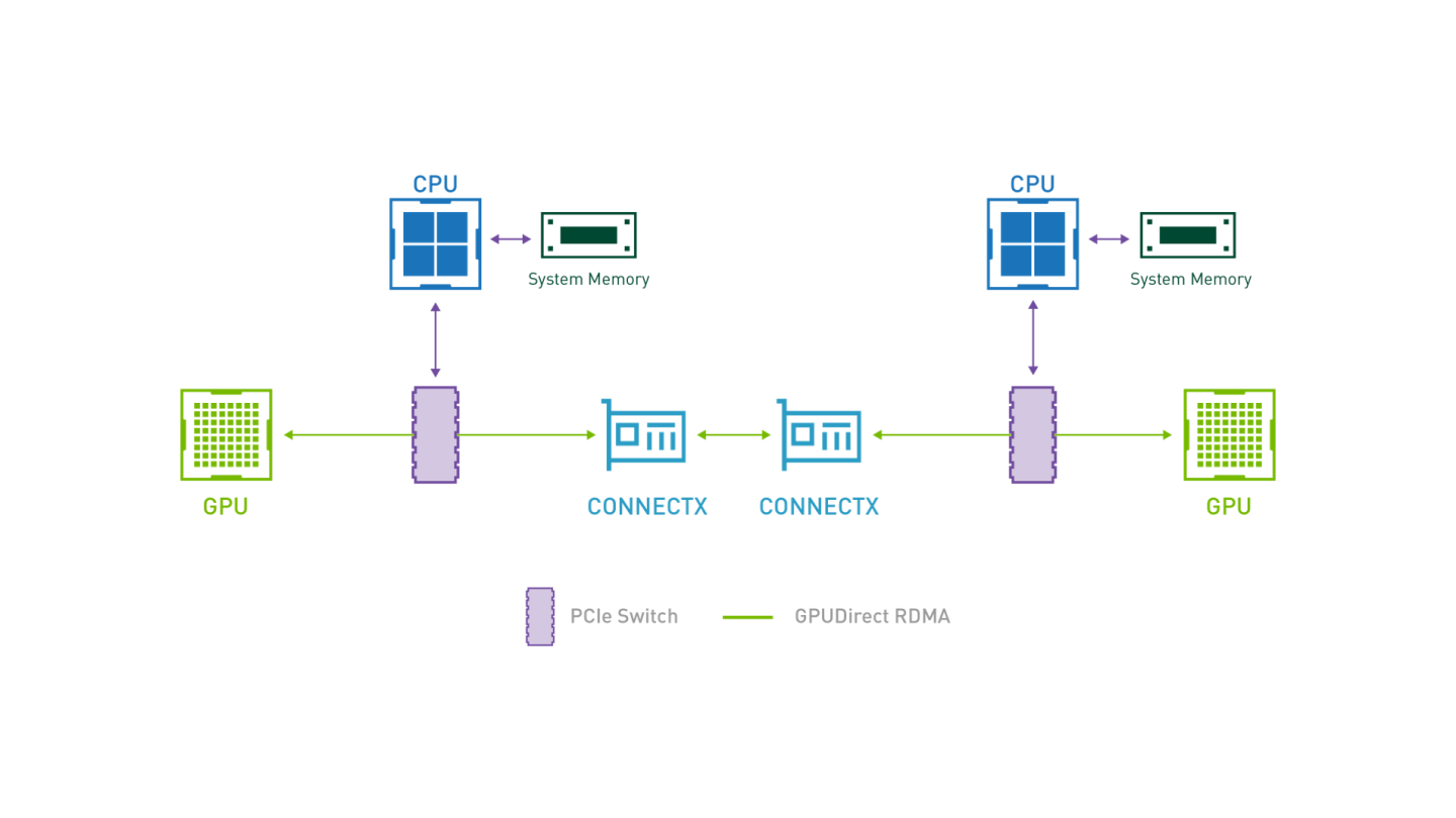
GPUDirect RDMA provides direct communication between NVIDIA GPUs in remote systems.
It bypasses the system CPUs and eliminates the required buffer copies of data via the system memory, resulting in a significant performance boost.
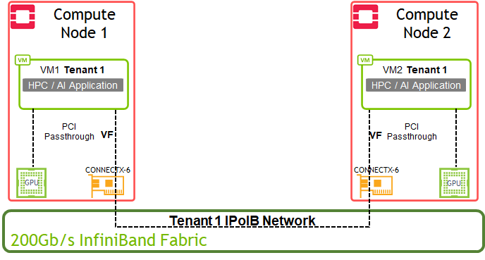
GPUDirect-enabled Bandwidth Test Topology
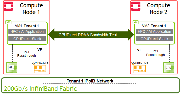
GDR-based IB_WRITE_BW Test over 200Gb/s InfiniBand Fabric
Performing an optimal GPUDirect RDMA Benchmark test requires a server with PCIe Bridges. The network adapter and GPU used in this test should be located under the same PCIe Bridge device and associated with the same CPU NUMA Node.
"lspci -tv" command can be used to display the device hierarchy and verify that the adapter / GPU PCI devices are hosted under the same PCIe Bridge
"lspci -vvv -s <PCI_Device_ID>" can be used to identify the NUMA node associated with the adapter / GPU PCI devices
GPUDirect RDMA in a virtual environment requires enablement of ATS (Address Translation Services) on the Network adapter as well as ACS (Access Control Services) on the PCIe Bridge and server BIOS.
In the servers used for this test, the Network-RDMA device (ConnectX-6) and GPU device (PCIe A100) share NUMA Node 1 and are connected under the same PCIe Bridge device.
For the GPUDirect RDMA benchmark test described in this section, the virtual instance guest OS must include CUDA and MLNX_OFED v5.6 and up.
Some of the configurations applied in this section are not persistent and therefore have to be reapplied after a server/instance reboot.
NVIDIA Multi-Instance GPU (MIG) must be disabled for this test.
Prepare the setup for running GPUDirect RDMA test over a virtualized environment by applying the following steps on both compute nodes:
Delete any existing instance on the compute nodes.
Install the mstflint package.
# dnf install mstflint
Locate the Connect-X Adapter PCI ID, and enable ATS and the Advanced PCI settings firmware parameters.
            # lspci | grep -i nox
c5:00.0 Infiniband controller: Mellanox Technologies MT28908 Family [ConnectX-6]
c5:00.1 Infiniband controller: Mellanox Technologies MT28908 Family [ConnectX-6]

# mstconfig -d c5:00.0 set ATS_ENABLED=true ADVANCED_PCI_SETTINGS=1
Reboot the compute nodes to apply the new firmware configuration.
Stop the server during boot process in BIOS menu and make sure ACS is enabled.

Increase the adapter's maximum accumulated read requests.
NoteThe value of 44 maximum requests that we used is a best practice value for a 200Gb/s test over a server with a PCIe Gen4 CPU.
In some cases, it might be required to increase the PCIe MaxReadReq size of the network device to 4KB, using the setpci command to further optimize the bandwidth test results.
# mstconfig -d c5:00.0 set MAX_ACC_OUT_READ=44
Reboot the compute nodes to apply the new firmware configuration.
Verify the adapter firmware parameters have been applied.
            # mstconfig -d c5:00.0 query | grep "ATS_ENABLED\|MAX_ACC_OUT_READ"
         MAX_ACC_OUT_READ                    44
         ATS_ENABLED                         True(1)
Enable ACS on the PCIe Bridge device that is hosting the adapter and GPU.
NoteIn many server architectures there are multiple chained PCIe Bridge devices serving a bulk of PCIe slots. It might be possible that the adapter and GPU will be connected to a different sub devices in this PCIe bridge chain.
The provided command will enable ACS on ALL PCIe Bridge devices in the system
This step is not persistent and has to be re-applied every time the server is rebooted while there are no running virtual instances
# for BDF in `lspci -d "*:*:*" | awk '{print $1}'`; do setpci -v -s ${BDF} ECAP_ACS+0x6.w=0x5D ; done;
Verify that ACS Direct Translation was enabled on the PCIe Bridge device hosting the adapter and GPU.
            # lspci -s <PCIe_Bridge_Device_ID> -vvv | grep  ACSCtl
                ACSCtl: SrcValid+ TransBlk- ReqRedir+ CmpltRedir+ UpstreamFwd+ EgressCtrl- DirectTrans+
On each of the compute nodes, start a virtual instance with direct SR-IOV port and A100 GPU.
NoteUse the image with GPUDirect RDMA stack prepared previously in this guide
Use the direct ports and network created previously in this guide
$ openstack server create --flavor m1.gpu --image centos8-stream-gdr --port direct1 vm1_gpu --availability-zone nova:overcloud-computesriov-ib-0.localdomain
$ openstack server create --flavor m1.gpu --image centos8-stream-gdr --port direct2 vm2_gpu --availability-zone nova:overcloud-computesriov-ib-1.localdomain
Login to both virtual instances and load the nvidia-peermem module:
            # modprobe nvidia-peermem
# lsmod | grep -i peermem
nvidia_peermem         16384  0
nvidia              39047168  3 nvidia_uvm,nvidia_peermem,nvidia_modeset
ib_core               438272  9 rdma_cm,ib_ipoib,nvidia_peermem,iw_cm,ib_umad,rdma_ucm,ib_uverbs,mlx5_ib,ib_cm
On both virtual instances, enable the GPU device persistence mode and lock the GPU clock on the maximum allowed speed.
NoteApply the following settings only when the bandwidth test result is not satisfactory.
Do NOT set a value higher than allowed per specific GPU device.
"nvidia-smi -i <device id> -q -d clock" command can be used to identify the Max Allowed Clock of a device.
For the A100 device we used in this test, the Max Allowed Clock is 1410 MHz.
            # nvidia-smi -i 0 -pm 1
Enabled persistence mode for GPU 00000000:CC:00.0.
All done.

# nvidia-smi -i 0 -lgc 1410
GPU clocks set to "(gpuClkMin 1410, gpuClkMax 1410)" for GPU 00000000:CC:00.0
All done.
Start GPUDirect RDMA ib_write_bw server on one of the virtual instances:
NoteGDR-enabled ib_write_bw is one of the tools installed on the guest image as part of the gpudirect-bench DIB element
It is possible to run network-based test without GPUDirect RDMA by omitting the "use_cuda" flag
            [root@host-11-11-11-235 stack]# ib_write_bw --report_gbits -F --use_cuda=0

************************************
* Waiting for client to connect... *
************************************
Start GPUDirect ib_write_bw client on the second instance by specifying the IP of the remote instance and a test packet size:
            [root@host-11-11-11-186 stack]# ib_write_bw  --report_gbits 11.11.11.235 -F --use_cuda=0 -s 32768
initializing CUDA
Listing all CUDA devices in system:
CUDA device 0: PCIe address is 05:00

Picking device No. 0
[pid = 3098, dev = 0] device name = [NVIDIA A100-PCIE-40GB]
creating CUDA Ctx
making it the current CUDA Ctx
cuMemAlloc() of a 65536 bytes GPU buffer
allocated GPU buffer address at 00007f9bcd200000 pointer=0x7f9bcd200000
---------------------------------------------------------------------------------------
                    RDMA_Write BW Test
 Dual-port       : OFF          Device         : mlx5_0
 Number of qps   : 1            Transport type : IB
 Connection type : RC           Using SRQ      : OFF
 PCIe relax order: ON
 ibv_wr* API     : ON
 TX depth        : 128
 CQ Moderation   : 1
 Mtu             : 4096[B]
 Link type       : IB
 Max inline data : 0[B]
 rdma_cm QPs     : OFF
 Data ex. method : Ethernet
---------------------------------------------------------------------------------------
 local address: LID 0x1b QPN 0x016a PSN 0xc9e104 RKey 0x044417 VAddr 0x007f9bcd208000
 remote address: LID 0x1c QPN 0x0282 PSN 0xd43e0a RKey 0x04443b VAddr 0x007f5b3d210000
---------------------------------------------------------------------------------------
 #bytes     #iterations    BW peak[Gb/sec]    BW average[Gb/sec]   MsgRate[Mpps]
 32768      5000             194.32             194.23             0.740946
---------------------------------------------------------------------------------------
deallocating RX GPU buffer 00007f9bcd200000
destroying current CUDA Ctx
NoteThis bandwidth test demonstrates near line-rate results of 194 Gb/s for a packet size of 32KB over 200Gb/s InfiniBand fabric with GPUDirect RDMA support. The servers used for this test support PCIe Gen4 and are optimized for GPUDirect RDMA.
Authors

|
Itai Levy Over the past few years, Itai Levy has worked as a Solutions Architect and member of the NVIDIA Networking “Solutions Labs” team. Itai designs and executes cutting-edge solutions around Cloud Computing, SDN, SDS and Security. His main areas of expertise include NVIDIA BlueField Data Processing Unit (DPU) solutions and accelerated OpenStack/K8s platforms. |