Technology Preview for DPF deployment with NVIDIA DOCA SNAP service
Created on May 29, 2025
Scope
This Technology Preview (TP) guide offers comprehensive instructions for deploying the NVIDIA DOCA SNAP service within a Kubernetes cluster using the DOCA Platform Framework. It details the step-by-step process for configuring the NVIDIA DOCA SNAP service over both TCP and RDMA transports on NVIDIA BlueField-3 DPUs.
This guide is designed for experienced system administrators, system engineers, and solution architects looking to provision Kubernetes pods with emulated PCIe block devices backed by networked storage. We will take full advantage of NVIDIA DPU hardware acceleration and offload capabilities, maximizing datacenter workload efficiency and performance.
This reference implementation, as the name implies, is a specific, opiniated deployment example designed to address the usecase described above.
While other approaches may exist to implement similar solutions, this document provides a detailed guide for this particular method.
Abbreviations and Acronyms
Term | Definition | Term | Definition |
BFB | BlueField Bootstream | OVN | Open Virtual Network |
BGP | Border Gateway Protocol | PVC | Persistent Volume Claim |
CNI | Container Network Interface | RDG | Reference Deployment Guide |
CRD | Custom Resource Definition | RDMA | Remote Direct Memory Access |
CSI | Container Storage Interface | SF | Scalable Function |
DOCA | Data Center Infrastructure-on-a-Chip Architecture | SFC | Service Function Chaining |
DOCA SNAP | NVIDIA® DOCA™ Storage-Defined Network Accelerated Processing | SPDK | Storage Performance Development Kit |
DPF | DOCA Platform Framework | SR-IOV | Single Root Input/Output Virtualization |
DPU | Data Processing Unit | TOR | Top of Rack |
DTS | DOCA Telemetry Service | VF | Virtual Function |
GENEVE | Generic Network Virtualization Encapsulation | VLAN | Virtual LAN (Local Area Network) |
HBN | Host Based Networking | VRR | Virtual Router Redundancy |
IPAM | IP Address Management | VTEP | Virtual Tunnel End Point |
K8S | Kubernetes | VXLAN | Virtual Extensible LAN |
MAAS | Metal as a Service |
Introduction
The NVIDIA BlueField-3 Data Processing Unit is a powerful infrastructure compute platform designed for high-speed processing of software-defined networking, storage, and cybersecurity. With a capacity of 400 Gb/s, BlueField-3 combines robust computing, high-speed networking, and extensive programmability to deliver hardware-accelerated, software-defined solutions for demanding workloads.
Deploying and managing DPUs and their associated DOCA services, especially at scale, can be quite challenging. Without a proper provisioning and orchestration system, handling the DPU lifecycle and configuring DOCA services place a heavy operational burden on system administrators. The NVIDIA DOCA Platform Foundation addresses this challenge by streamlining and automating the lifecycle management of DOCA services.
NVIDIA DOCA unlocks the full potential of the BlueField platform, enabling rapid development of applications and services that offload, accelerate, and isolate data center workloads. One such example is NVIDIA DOCA SNAP, a DPU storage service that is designed to accelerate and optimize storage protocol by leveraging the capabilities of NVIDIA's BlueField DPUs. NVIDIA DOCA SNAP technology encompasses a family of services that enable hardware-accelerated virtualization of local storage running on NVIDIA BlueField products. The SNAP services present networked storage as local block devices to the host, emulating local drives on the PCIe bus. At its core, DOCA SNAP enables high-performance, low-latency access to storage by allowing applications to interact directly with raw block devices - bypassing traditional filesystem overhead. As part of the DPF deployment model, the DOCA SNAP solution is composed of multiple functional components packaged into containers, which are deployed across both the x86 and DPU Kubernetes clusters.
This guide is similar to the RDG for DPF with OVN-Kubernetes and HBN Services document, which covers K8s cluster deployment with NVIDIA DOCA Host-Based Networking Service and OVN-Kubernetes CNI network plugin. In this guide, HBN enables the routing of OVN accelerated workload traffic together with storage protocol traffic on the server side by using BlueField as a BGP router.
This reference implementation leverages open-source components, and provides an end-to-end walkthrough of the deployment process, including:
- Infrastructure provisioning with MAAS
- Integration with NVIDIA’s DPF
- Deployment and orchestration of DPU-based services inside the Kubernetes cluster
- Configuration of BlueField devices with enabled NVMe emulation for DOCA SNAP service
- Management of DPU resources and workloads using Kubernetes-native constructs
This guide provides a comprehensive, practical example of installing the DPF system with NVIDIA DOCA SNAP service on a Kubernetes cluster according to the "Storage Development Guide".
In our guide we used the Storage Performance Development Kit (SPDK) as an example of storage backend service.
This storage backend service is used only for demonstration purposes and is not intended or supported for production usecases.
References
- NVIDIA BlueField DPU
- NVIDIA DOCA
- NVIDIA DOCA HBN Service
- NVIDIA DOCA SNAP Service
- NVIDIA DPF Release Notes
- NVIDIA DPF GitHub Repository
- NVIDIA DPF System Overview
- NVIDIA Ethernet Switching
- NVIDIA Cumulus Linux
- NVIDIA Network Operator
- What is K8s?
- Kubespray
- OVN-Kubernetes
Solution Architecture
Key Components and Technologies
NVIDIA BlueField® Data Processing Unit (DPU)
The NVIDIA® BlueField® data processing unit (DPU) ignites unprecedented innovation for modern data centers and supercomputing clusters. With its robust compute power and integrated software-defined hardware accelerators for networking, storage, and security, BlueField creates a secure and accelerated infrastructure for any workload in any environment, ushering in a new era of accelerated computing and AI.
NVIDIA DOCA Software Framework
NVIDIA DOCA™ unlocks the potential of the NVIDIA® BlueField® networking platform. By harnessing the power of BlueField DPUs and SuperNICs, DOCA enables the rapid creation of applications and services that offload, accelerate, and isolate data center workloads. It lets developers create software-defined, cloud-native, DPU- and SuperNIC-accelerated services with zero-trust protection, addressing the performance and security demands of modern data centers.
10/25/40/50/100/200 and 400G Ethernet Network Adapters
The industry-leading NVIDIA® ConnectX® family of smart network interface cards (SmartNICs) offer advanced hardware offloads and accelerations.
NVIDIA Ethernet adapters enable the highest ROI and lowest Total Cost of Ownership for hyperscale, public and private clouds, storage, machine learning, AI, big data, and telco platforms.
The NVIDIA® LinkX® product family of cables and transceivers provides the industry’s most complete line of 10, 25, 40, 50, 100, 200, and 400GbE in Ethernet and 100, 200 and 400Gb/s InfiniBand products for Cloud, HPC, hyperscale, Enterprise, telco, storage and artificial intelligence, data center applications.
NVIDIA Spectrum Ethernet Switches
Flexible form-factors with 16 to 128 physical ports, supporting 1GbE through 400GbE speeds.
Based on a ground-breaking silicon technology optimized for performance and scalability, NVIDIA Spectrum switches are ideal for building high-performance, cost-effective, and efficient Cloud Data Center Networks, Ethernet Storage Fabric, and Deep Learning Interconnects.
NVIDIA combines the benefits of NVIDIA Spectrum™ switches, based on an industry-leading application-specific integrated circuit (ASIC) technology, with a wide variety of modern network operating system choices, including NVIDIA Cumulus® Linux , SONiC and NVIDIA Onyx®.
NVIDIA® Cumulus® Linux is the industry's most innovative open network operating system that allows you to automate, customize, and scale your data center network like no other.
The NVIDIA Network Operator simplifies the provisioning and management of NVIDIA networking resources in a Kubernetes cluster. The operator automatically installs the required host networking software - bringing together all the needed components to provide high-speed network connectivity. These components include the NVIDIA networking driver, Kubernetes device plugin, CNI plugins, IP address management (IPAM) plugin and others. The NVIDIA Network Operator works in conjunction with the NVIDIA GPU Operator to deliver high-throughput, low-latency networking for scale-out, GPU computing clusters.
Kubernetes is an open-source container orchestration platform for deployment automation, scaling, and management of containerized applications.
Kubespray is a composition of Ansible playbooks, inventory, provisioning tools, and domain knowledge for generic OS/Kubernetes clusters configuration management tasks and provides:
- A highly available cluster
- Composable attributes
- Support for most popular Linux distributions
OVN-Kubernetes (Open Virtual Networking - Kubernetes) is an open-source project that provides a robust networking solution for Kubernetes clusters with OVN (Open Virtual Networking) and Open vSwitch (Open Virtual Switch) at its core. It is a Kubernetes networking conformant plugin written according to the CNI (Container Network Interface) specifications.
RDMA is a technology that allows computers in a network to exchange data without involving the processor, cache or operating system of either computer.
Like locally based DMA, RDMA improves throughput and performance and frees up compute resources.
Solution Design
Solution Logical Design
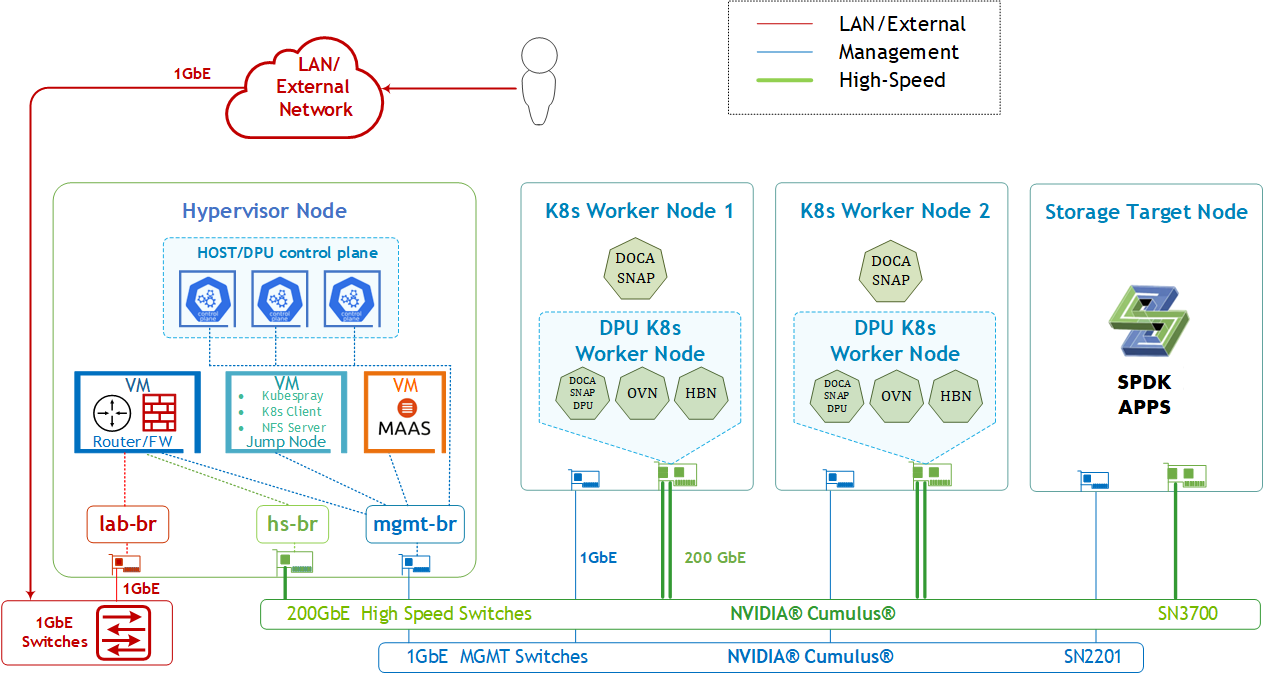
The logical design includes the following components:
1 x Hypervisor node (KVM based) with ConnectX-7
- 1 x Firewall VM
- 1 x Jump VM
- 1 x MAAS VM
- 3 x VMs running all K8s management components for Host/DPU clusters
- 2 x Worker nodes, each with a 1 x BlueField-3 NIC
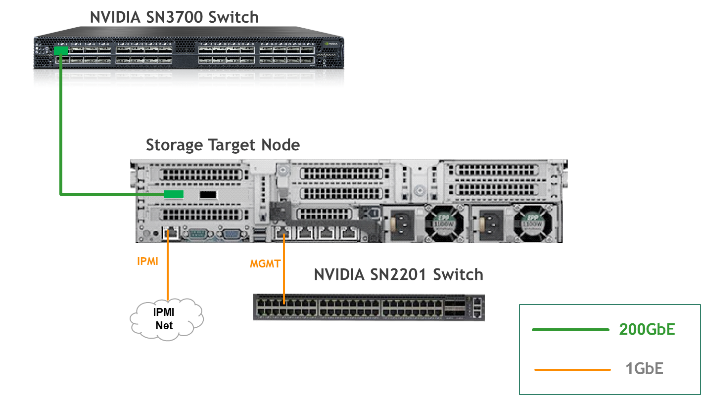
- Storage Target Node with ConnectX-7 and SPDK target apps
- Single 200 GbE High-Speed (HS) switch
- 1 GbE Host Management network
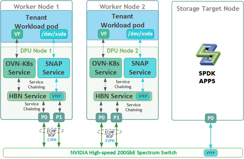
SFC Logical Diagram
The DOCA Platform Framework simplifies DPU management by providing orchestration through a K8s API. It handles the provisioning and lifecycle management of DPUs, orchestrates specialized DPU services, and automates service function chaining (SFC) tasks. This ensures seamless deployment of NVIDIA DOCA services and OVN-Kubernetes CNI, allowing traffic to be efficiently offloaded and routed through HBN's data plane. The SFC logical diagram implemented in this guide is shown below.
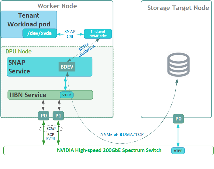
Disk Emulation Logical Diagram
The following logical diagram demonstrates the main components involved in a disk mount procedure to tenant workload pod.
Upon receiving a new request for an emulated NVMe drive, DOCA SNAP components bring a block device (BDEV) via NVMe-oF using either RDMA or TCP storage protocols to the required K8s worker node. The DPU then emulates it as a block device on the x86 host via the "BlueField NVMe SNAP Controller" .
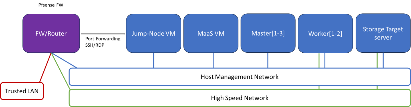
Firewall Design
The pfSense firewall in this solution serves a dual purpose:
- Firewall – Provides an isolated environment for the DPF system, ensuring secure operations
- Router – Enables internet access and connectivity between the host management network and the high-speed network
Port-forwarding rules for SSH and RDP are configured on the firewall to route traffic to the jump node’s IP address in the host management network. From the jump node, administrators can manage and access various devices in the setup, as well as handle the deployment of the Kubernetes (K8s) cluster and DPF components.
The following diagram illustrates the firewall design used in this solution:
Software Stack Components
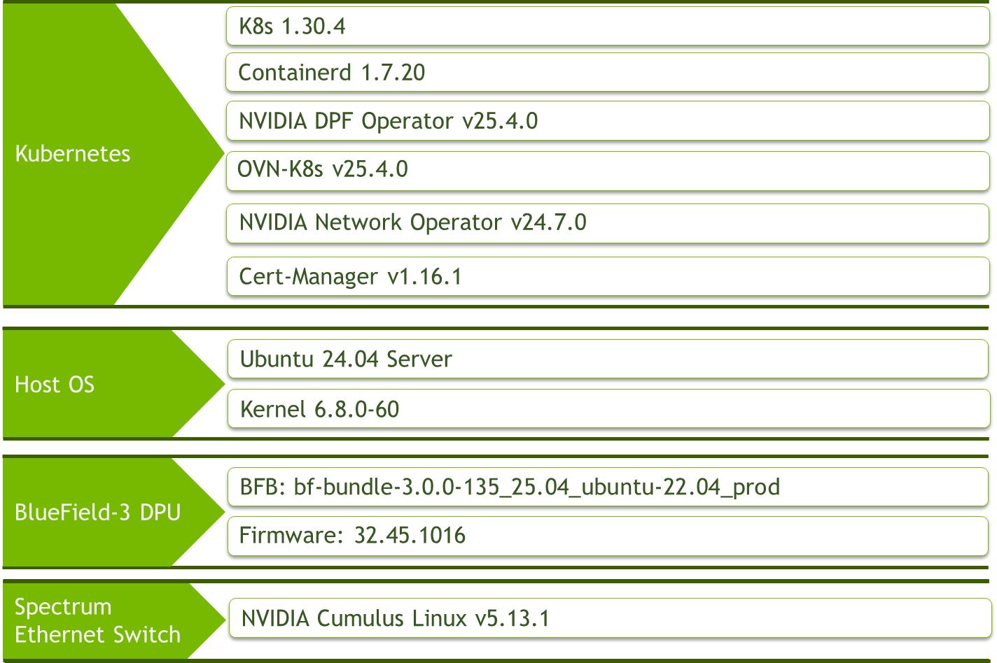
Make sure to use the exact same versions for the software stack as described above.
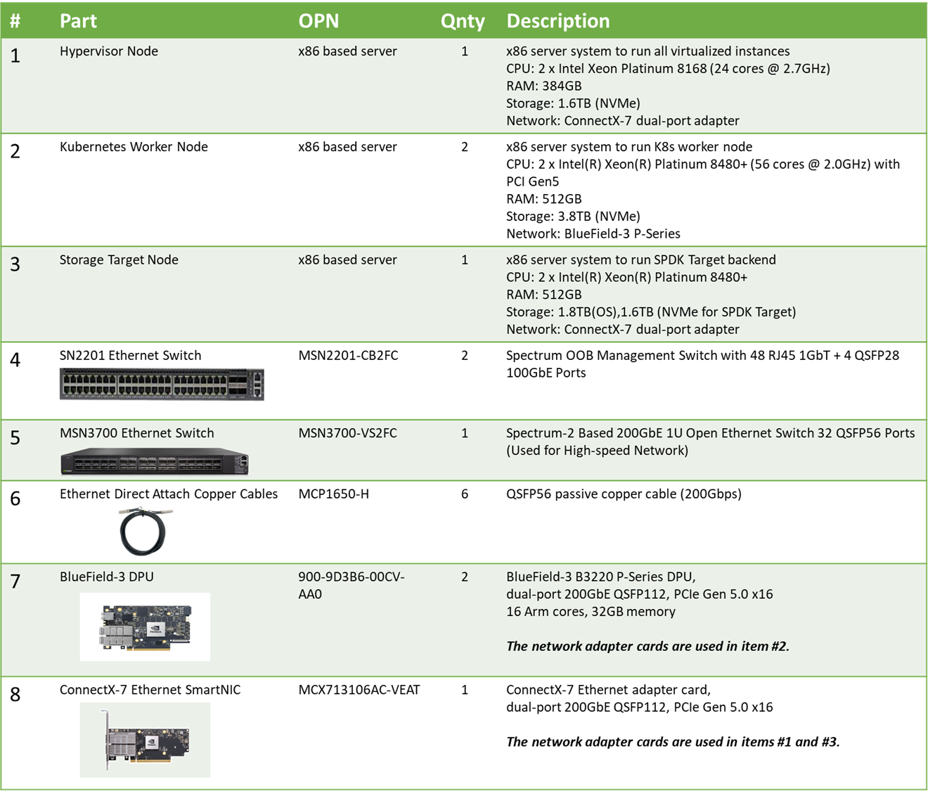
Bill of Materials
Deployment and Configuration
Node and Switch Definitions
These are the definitions and parameters used for deploying the demonstrated fabric:
Switch Port Usage | ||
| 1 | swp1-4 |
| 1 | swp1,11-14,32 |
Hosts | |||||
Rack | Server Type | Server Name | Switch Port | IP and NICs | Default Gateway |
Rack1 | Hypervisor Node |
| mgmt-switch: hs-switch: | lab-br (interface eno1): Trusted LAN IP mgmt-br (interface eno2): - hs-br (interface ens2f0np0): | Trusted LAN GW |
Rack1 | Storage Target Node |
| mgmt-switch: hs-switch: | enp1s0f0: 10.0.110.25/24 enp144s0f0np0: 10.0.124.1/24 | 10.0.110.254 |
Rack1 | Worker Node |
| mgmt-switch: hs-switch: | ens15f0: 10.0.110.21/24 ens5f0np0/ens5f1np1: 10.0.120.0/22 | 10.0.110.254 |
Rack1 | Worker Node |
| mgmt-switch: hs-switch: | ens15f0: 10.0.110.22/24 ens5f0np0/ens5f1np1: 10.0.120.0/22 | 10.0.110.254 |
Rack1 | Firewall (Virtual) |
| - | WAN (lab-br): Trusted LAN IP LAN (mgmt-br): 10.0.110.254/24 OPT1 (hs-br): 172.169.50.1/30 | Trusted LAN GW |
Rack1 | Jump Node (Virtual) |
| - | enp1s0: 10.0.110.253/24 | 10.0.110.254 |
Rack1 | MAAS (Virtual) |
| - | enp1s0: 10.0.110.252/24 | 10.0.110.254 |
Rack1 | Master Node (Virtual) |
| - | enp1s0: 10.0.110.1/24 | 10.0.110.254 |
Rack1 | Master Node (Virtual) |
| - | enp1s0: 10.0.110.2/24 | 10.0.110.254 |
Rack1 | Master Node (Virtual) |
| - | enp1s0: 10.0.110.3/24 | 10.0.110.254 |
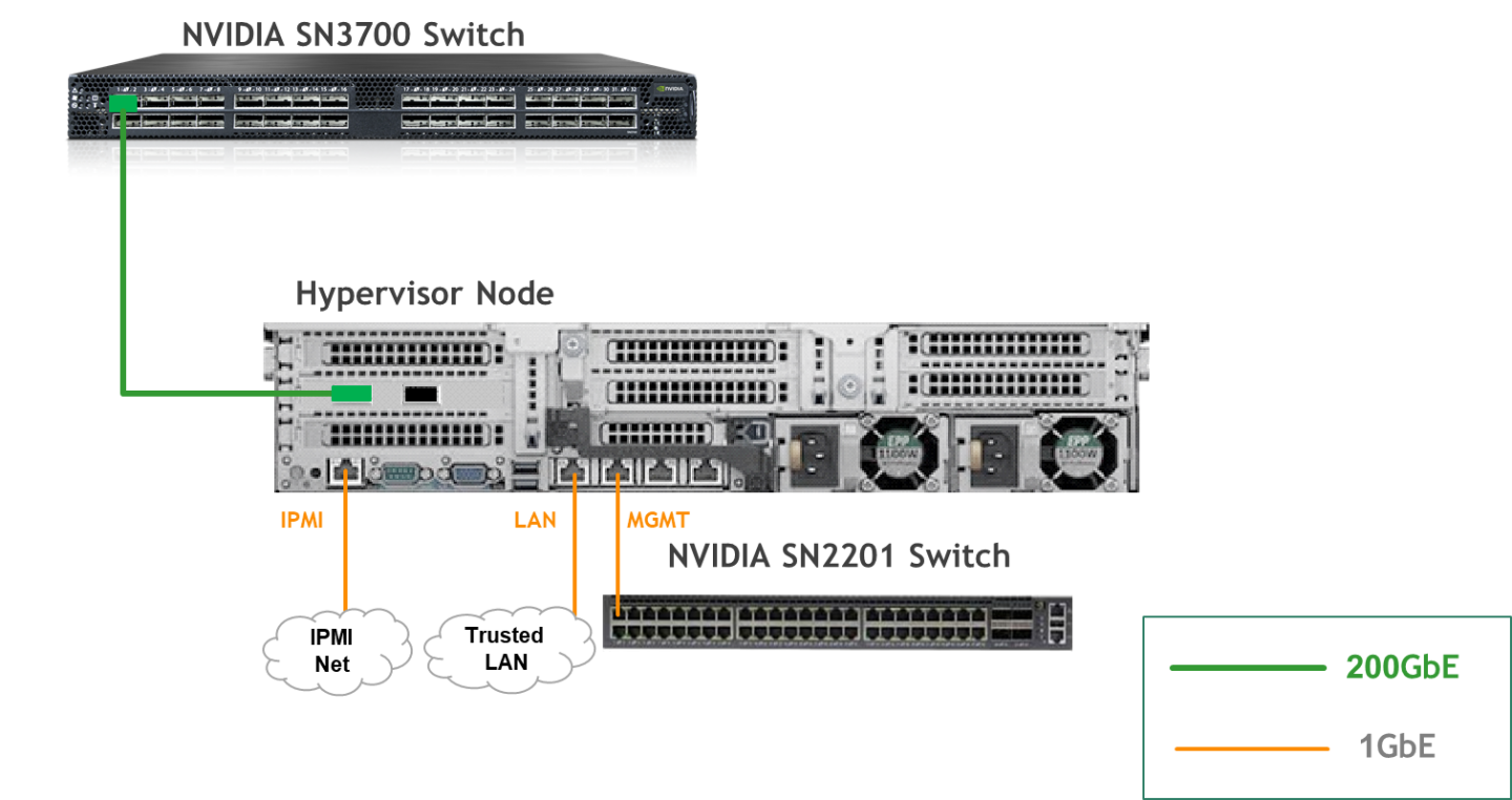
Wiring
Hypervisor Node
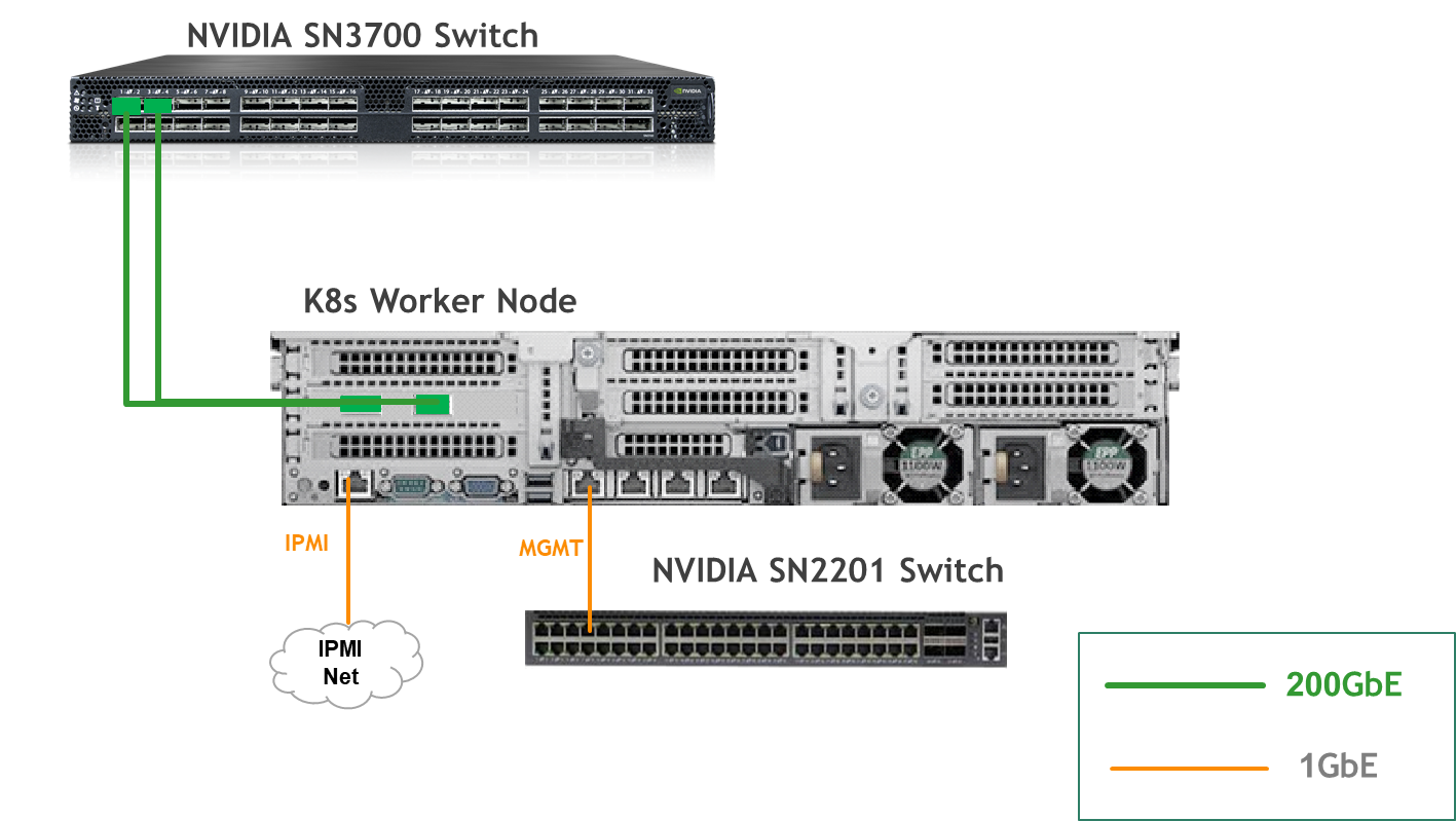
K8s Worker Node
Storage Target Node
Fabric Configuration
Updating Cumulus Linux
As a best practice, make sure to use the latest released Cumulus Linux NOS version.
For information on how to upgrade Cumulus Linux, refer to the Cumulus Linux User Guide.
Configuring the Cumulus Linux Switch
The SN3700 switch (hs-switch), is configured as follows:
The following commands configure BGP unnumbered on
hs-switch.Cumulus Linux enables the BGP equal-cost multipathing (ECMP) option by default.
SN3700 Switch Console
            nv set bridge domain br_default vlan 10 vni 10
nv set evpn enable on
nv set interface lo ip address 11.0.0.101/32
nv set interface lo type loopback
nv set interface swp1 ip address 172.169.50.2/30
nv set interface swp1 link speed auto
nv set interface swp1-32 type swp
nv set interface swp32 bridge domain br_default access 10
nv set nve vxlan enable on
nv set nve vxlan source address 11.0.0.101
nv set qos roce enable on
nv set qos roce mode lossless
nv set router bgp autonomous-system 65001
nv set router bgp enable on
nv set router bgp graceful-restart mode full
nv set router bgp router-id 11.0.0.101
nv set system hostname hs-switch
nv set vrf default router bgp address-family ipv4-unicast enable on
nv set vrf default router bgp address-family ipv4-unicast redistribute connected enable on
nv set vrf default router bgp address-family ipv4-unicast redistribute static enable on
nv set vrf default router bgp address-family ipv6-unicast enable on
nv set vrf default router bgp address-family ipv6-unicast redistribute connected enable on
nv set vrf default router bgp address-family l2vpn-evpn enable on
nv set vrf default router bgp enable on
nv set vrf default router bgp neighbor swp11 peer-group hbn
nv set vrf default router bgp neighbor swp11 type unnumbered
nv set vrf default router bgp neighbor swp12 peer-group hbn
nv set vrf default router bgp neighbor swp12 type unnumbered
nv set vrf default router bgp neighbor swp13 peer-group hbn
nv set vrf default router bgp neighbor swp13 type unnumbered
nv set vrf default router bgp neighbor swp14 peer-group hbn
nv set vrf default router bgp neighbor swp14 type unnumbered
nv set vrf default router bgp path-selection multipath aspath-ignore on
nv set vrf default router bgp peer-group hbn address-family l2vpn-evpn enable on
nv set vrf default router bgp peer-group hbn remote-as external
nv set vrf default router static 0.0.0.0/0 address-family ipv4-unicast
nv set vrf default router static 0.0.0.0/0 via 172.169.50.1 type ipv4-address
nv set vrf default router static 10.0.110.0/24 address-family ipv4-unicast
nv set vrf default router static 10.0.110.0/24 via 172.169.50.1 type ipv4-address

nv config apply -y
The SN2201 switch (mgmt-switch) is configured as follows:
SN2201 Switch Console
            nv set bridge domain br_default untagged 1
nv set interface swp1-4 link state up
nv set interface swp1-4 type swp
nv set interface swp1-4 bridge domain br_default
nv config apply -y
Host Configuration
Make sure that the BIOS settings on the worker node servers have SR-IOV enabled and that the servers are tuned for maximum performance.
All worker nodes must have the same PCIe placement for the BlueField-3 DPUs and must show the same interface name.
Hypervisor Installation and Configuration
The hypervisor used in this guide is based on Ubuntu 24.04 with KVM.
While this document does not detail the KVM installation process, it is important to note that the setup requires the following ISOs to deploy the Firewall, Jump, and MAAS virtual machines (VMs):
- Ubuntu 24.04
- pfSense-CE-2.7.2
To implement the solution, three Linux bridges must be created on the hypervisor:
Ensure a DHCP record is configured for the lab-br bridge interface in your trusted LAN to assign it an IP address.
lab-br– connects the Firewall VM to the trusted LAN.mgmt-br– Connects the various VMs to the host management network.hs-br– Connects the Firewall VM to the high-speed network.
Additionally, an MTU of 9000 must be configured on the management and high-speed bridges (mgmt-br and hs-br) as well as their uplink interfaces to ensure optimal performance.
Hypervisor netplan configuration
            network:
    ethernets:
        eno1:
            dhcp4: false
        eno2:
            dhcp4: false
            mtu: 9000
        ens2f0np0:
            dhcp4: false
            mtu: 9000
    bridges:
      lab-br:
         interfaces: [eno1]
         dhcp4: true
      mgmt-br:
         interfaces: [eno2]
         dhcp4: false
         mtu: 9000
      hs-br:
         interfaces: [ens2f0np0]
         dhcp4: false
         mtu: 9000
    version: 2
Apply the configuration:
Hypervisor Console
$ sudo netplan apply
Prepare Infrastructure Servers
Firewall VM - pfSense Installation and Interface Configuration
Download the pfSense CE (Community Edition) ISO to your hypervisor and proceed with the software installation.
Suggested spec:
- vCPU: 2
- RAM: 2GB
- Storage: 10GB
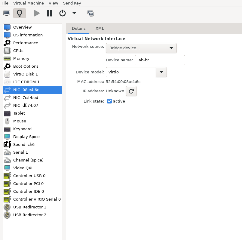
Network interfaces
- Bridge device connected to
lab-br - Bridge device connected to
mgmt-br - Bridge device connected to
hs-br
- Bridge device connected to
The Firewall VM must be connected to all three Linux bridges on the hypervisor. Before beginning the installation, ensure that three virtual network interfaces of type "Bridge device" are configured. Each interface should be connected to a different bridge (lab-br, mgmt-br, and hs-br) as illustrated in the diagram below.
After completing the installation, the setup wizard displays a menu with several options, such as "Assign Interfaces" and "Reboot System." During this phase, you must configure the network interfaces for the Firewall VM.
Select Option 2: "Set interface(s) IP address" and configure the interfaces as follows:
- WAN (lab-br) – Trusted LAN IP (Static/DHCP)
- LAN (mgmt-br) – Static IP 10.0.110.254/24
- OPT1 (hs-br) – Static IP 172.169.50.1/30
- Once the interface configuration is complete, use a web browser within the host management network to access the Firewall web interface and finalize the configuration.
Next, proceed with the installation of the Jump VM. This VM will serve as a platform for running a browser to access the Firewall’s web interface for post-installation configuration.
Jump VM
Suggested specifications:
- vCPU: 4
- RAM: 8GB
- Storage: 50GB
- Network interface: Bridge device, connected to
mgmt-br
Procedure:
Proceed with a standard Ubuntu 24.04 installation. Use the following login credentials across all hosts in this setup:
Username
Password
depuser
user
Enable internet connectivity and DNS resolution by creating the following Netplan configuration:
NoteUse
10.0.110.254as a temporary DNS nameserver until the MAAS VM is installed and configured. After completing the MAAS installation, update the Netplan file to replace this address with the MAAS IP:10.0.110.252.Jump Node netplan
network: ethernets: enp1s0: dhcp4:
falseaddresses: [10.0.110.253/24] nameservers: search: [dpf.rdg.local.domain] addresses: [10.0.110.254] routes: - to:defaultvia:10.0.110.254version:2Apply the configuration:
Jump Node Console
depuser@jump:~$ sudo netplan apply
Update and upgrade the system:
Jump Node Console
            depuser@jump:~$ sudo apt update -y
depuser@jump:~$ sudo apt upgrade -y
Install and configure the Xfce desktop environment and XRDP (complementary packages for RDP):
Jump Node Console
            depuser@jump:~$ sudo apt install -y xfce4 xfce4-goodies
depuser@jump:~$ sudo apt install -y xrdp
depuser@jump:~$ echo "xfce4-session" | tee .xsession
depuser@jump:~$ sudo systemctl restart xrdp
Install Firefox for accessing the Firewall web interface:
Jump Node Console
$ sudo apt install -y firefox
Install and configure an NFS server with the
/mnt/dpf_sharedirectory:Jump Node Console
            $ sudo apt install -y nfs-server
$ sudo mkdir -m 777 /mnt/dpf_share
$ sudo vi /etc/exports
Add the following line to
/etc/exports:Jump Node Console
/mnt/dpf_share 10.0.110.0/24(rw,sync,no_subtree_check)
Restart the NFS server:
Jump Node Console
$ sudo systemctl restart nfs-server
Create the directory
bfbunder/mnt/dpf_sharewith the same permissions as the parent directory:Jump Node Console
$ sudo mkdir -m 777 /mnt/dpf_share/bfb
Generate an SSH key pair for
depuserin the jump node (later on will be imported for the MAAS admin user to provide passwordless login to provisioned servers):Jump Node Console
depuser@jump:~$ ssh-keygen -t rsa
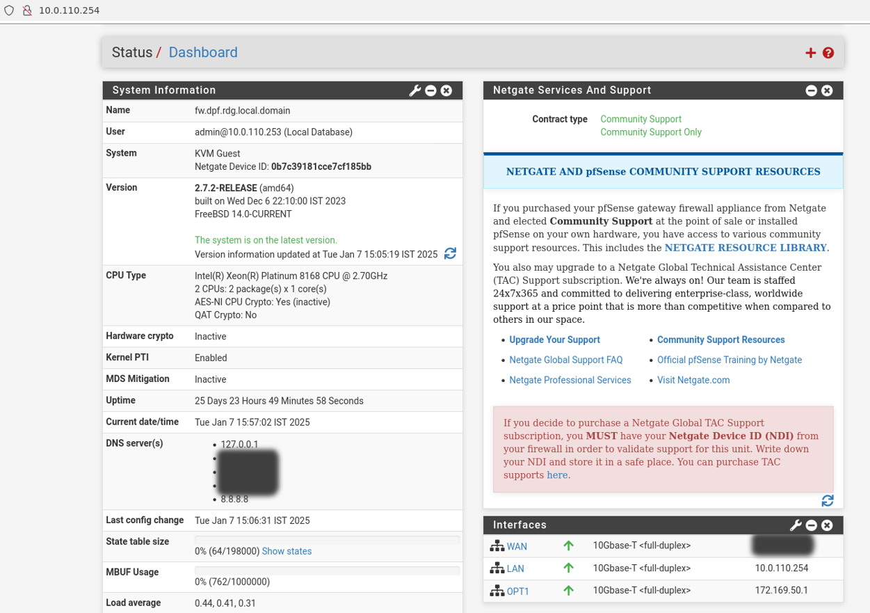
Firewall VM – Web Configuration
From your Jump node, open Firefox web browser and go to the pfSense web UI (http://10.0.110.254, default credentials are admin/pfsense). You should see a page similar to the following:
The IP addresses from the trusted LAN network under "DNS servers" and "Interfaces - WAN" are blurred.
Proceed with the following configurations:
The following screenshots display only part of the configuration view. Make sure not to miss any of the steps mentioned below!
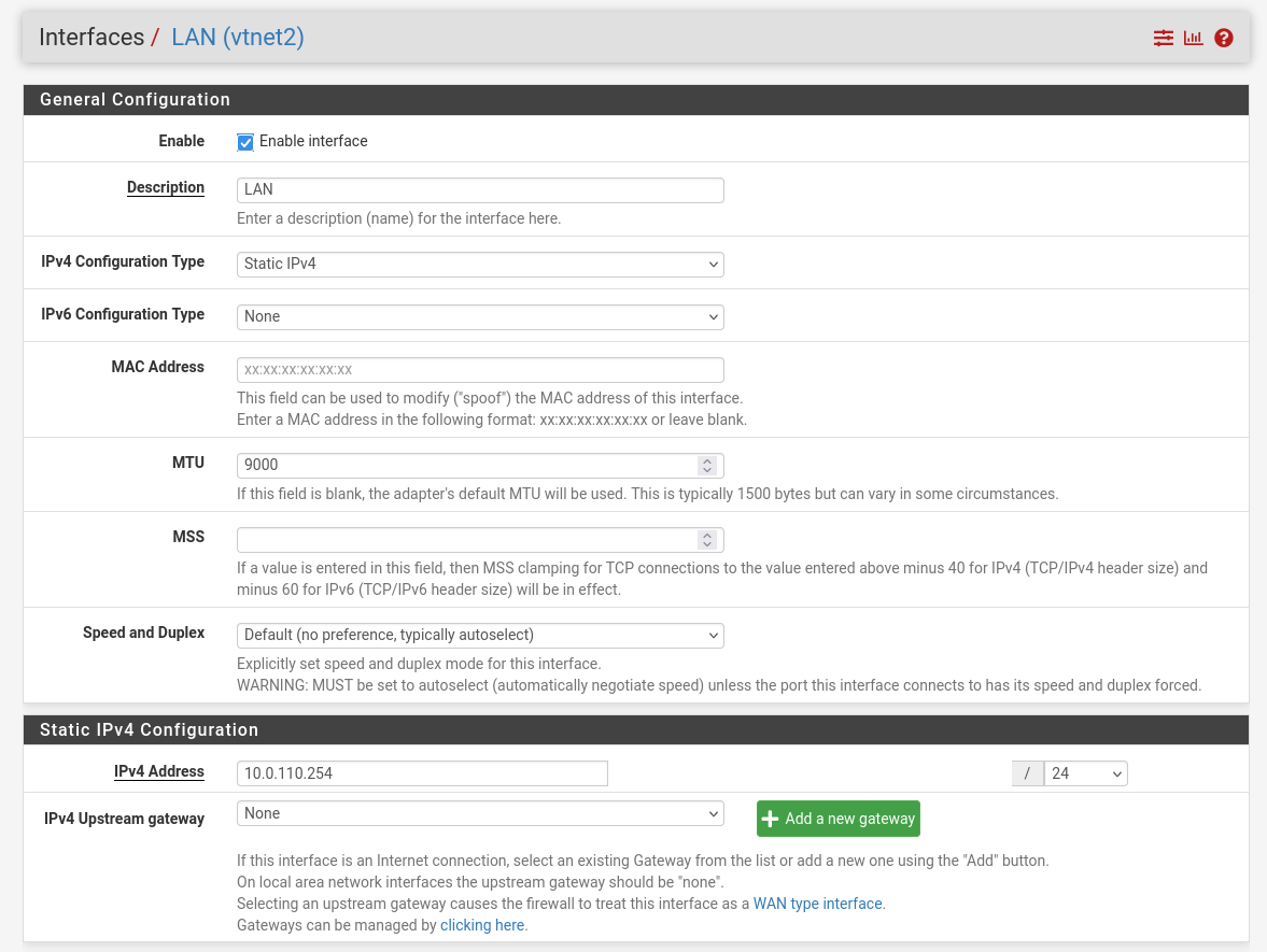
Interfaces
- WAN – mark “Enable interface”, unmark “Block private networks and loopback addresses”
- LAN – mark “Enable interface”, “IPv4 configuration type”: Static IPv4 ("IPv4 Address": 10.0.110.254/24, "IPv4 Upstream Gateway": None), “MTU”: 9000
OPT1 – mark “Enable interface”, “IPv4 configuration type”: Static IPv4 ("IPv4 Address": 172.169.50.1/30, "IPv4 Upstream Gateway": None), “MTU”: 9000
Firewall:
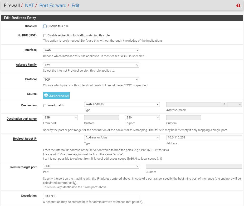
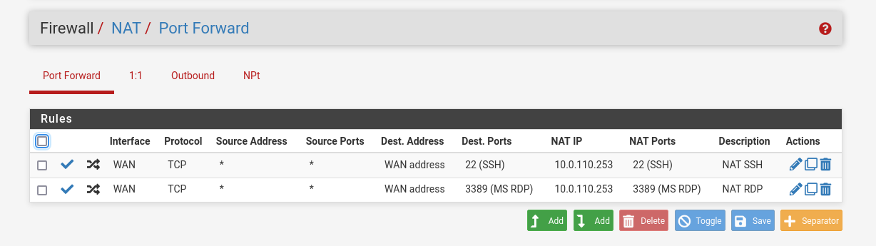
- NAT -> Port Forward -> Add rule -> “Interface”: WAN, “Address Family”: IPv4, “Protocol”: TCP, “Destination”: WAN address, “Destination port range”: (“From port”: SSH, “To port”: SSH), “Redirect target IP”: (“Type”: Address or Alias, “Address”: 10.0.110.253), “Redirect target port”: SSH, “Description”: NAT SSH
NAT -> Port Forward -> Add rule -> “Interface”: WAN, “Address Family”: IPv4, “Protocol”: TCP, “Destination”: WAN address, “Destination port range”: (“From port”: MS RDP, “To port”: MS RDP), “Redirect target IP”: (“Type”: Address or Alias, “Address”: 10.0.110.253), “Redirect target port”: MS RDP, “Description”: NAT RDP
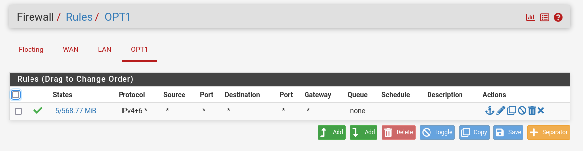
Rules -> OPT1 -> Add rule -> “Action”: Pass, “Interface”: OPT1, “Address Family”: IPv4+IPv6, “Protocol”: Any, “Source”: Any, “Destination”: Any
System:
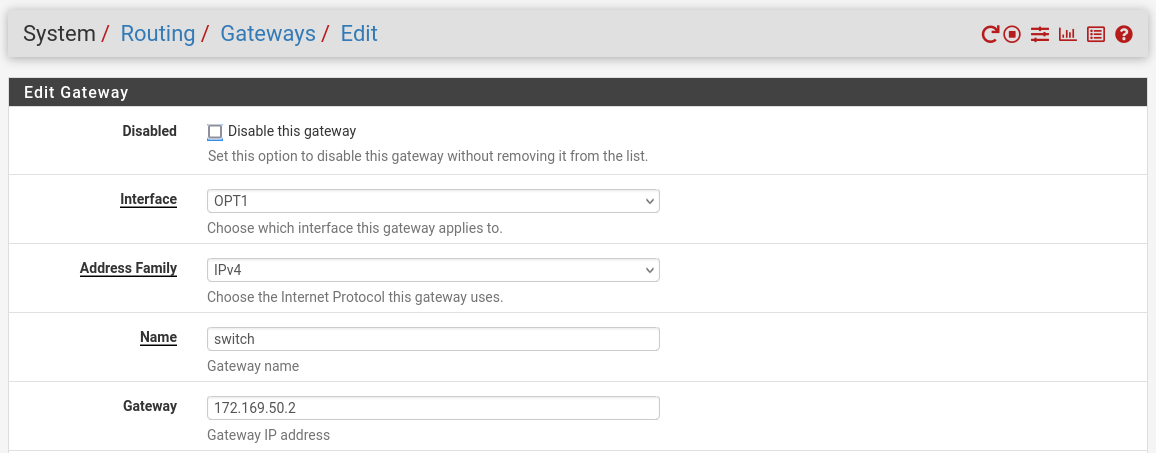
Routing → Gateways → Add → “Interface”: OPT1, “Address Family”: IPv4, “Name”: switch, “Gateway”: 172.169.50.2 → Click "Save"→ Under "Default Gateway" - "Default gateway IPv4" choose WAN_DHCP → Click "Save"
 Note
NoteNote that the IP addresses from the Trusted LAN network under "Gateway" and "Monitor IP" are blurred.
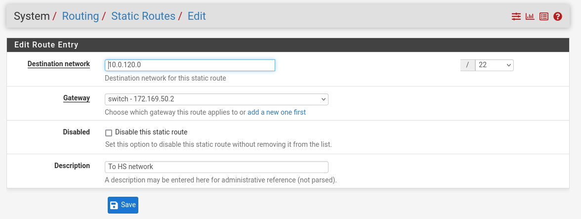
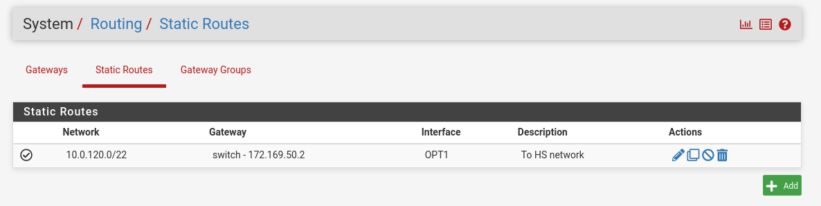
Routing → Static Routes → Add → “Destination network”: 10.0.120.0/22, “Gateway”: switch – 172.169.50.2, “Description”: To HS network → Click "Save"
MAAS VM
Suggested specifications:
- vCPU: 4
- RAM: 4GB
- Storage: 50GB
- Network interface: Bridge device, connected to
mgmt-br
Procedure:
- Perform a regular Ubuntu installation on the MAAS VM.
Create the following Netplan configuration to enable internet connectivity and DNS resolution:
NoteUse
10.0.110.254as a temporary DNS nameserver. After the MAAS installation, replace this with the MAAS IP address (10.0.110.252) in both the Jump and MAAS VM Netplan files.MaaS netplan
network: ethernets: enp1s0: dhcp4:
falseaddresses: [10.0.110.252/24] nameservers: search: [dpf.rdg.local.domain] addresses: [10.0.110.254] routes: - to:defaultvia:10.0.110.254version:2Apply the netplan configuration:
MaaS Console
depuser@maas:~$ sudo netplan apply
Update and upgrade the system:
MaaS Console
            depuser@maas:~$ sudo apt update -y
depuser@maas:~$ sudo apt upgrade -y
Install PostgreSQL and configure the database for MAAS:
MaaS Console
            $ sudo -i
# apt install -y postgresql
# systemctl enable --now postgresql
# systemctl disable --now systemd-timesyncd
# export MAAS_DBUSER=maasuser
# export MAAS_DBPASS=maaspass
# export MAAS_DBNAME=maas
# sudo -i -u postgres psql -c "CREATE USER \"$MAAS_DBUSER\" WITH ENCRYPTED PASSWORD '$MAAS_DBPASS'"
# sudo -i -u postgres createdb -O "$MAAS_DBUSER" "$MAAS_DBNAME"
Install MAAS:
MaaS Console
# snap install maas
Initialize MAAS:
MaaS Console
# maas init region+rack --maas-url http://10.0.110.252:5240/MAAS --database-uri "postgres://$MAAS_DBUSER:$MAAS_DBPASS@localhost/$MAAS_DBNAME"
Create an admin account:
MaaS Console
# maas createadmin --username admin --password admin --email admin@example.com
Save the admin API key:
MaaS Console
# maas apikey --username admin > admin-apikey
Log in to the MAA server:
MaaS Console
# maas login admin http://localhost:5240/MAAS "$(cat admin-apikey)"
Configure MAAS (Substitute <Trusted_LAN_NTP_IP> and <Trusted_LAN_DNS_IP> with the IP addresses in your environment):
MaaS Console
            # maas admin domain update maas name="dpf.rdg.local.domain"
# maas admin maas set-config name=ntp_servers value="<Trusted_LAN_NTP_IP>"
# maas admin maas set-config name=network_discovery value="disabled"
# maas admin maas set-config name=upstream_dns value="<Trusted_LAN_DNS_IP>"
# maas admin maas set-config name=dnssec_validation value="no"
# maas admin maas set-config name=default_osystem value="ubuntu"
Define and configure IP ranges and subnets:
MaaS Console
            # maas admin ipranges create type=dynamic start_ip="10.0.110.51" end_ip="10.0.110.120"
# maas admin ipranges create type=dynamic start_ip="10.0.110.21" end_ip="10.0.110.30"
# maas admin ipranges create type=reserved start_ip="10.0.110.10" end_ip="10.0.110.10" comment="c-plane VIP"
# maas admin ipranges create type=reserved start_ip="10.0.110.200" end_ip="10.0.110.200" comment="kamaji VIP"
# maas admin ipranges create type=reserved start_ip="10.0.110.251" end_ip="10.0.110.254" comment="dpfmgmt"
# maas admin vlan update 0 untagged dhcp_on=True primary_rack=maas
# maas admin dnsresources create fqdn=kube-vip.dpf.rdg.local.domain ip_addresses=10.0.110.10
# maas admin dnsresources create fqdn=jump.dpf.rdg.local.domain ip_addresses=10.0.110.253
# maas admin dnsresources create fqdn=fw.dpf.rdg.local.domain ip_addresses=10.0.110.254
# maas admin fabrics create
Success.
Machine-readable output follows:
{
"class_type": null,
"name": "fabric-1",
"id": 1,
...
# maas admin subnets create name="fake-dpf" cidr="20.20.20.0/24" fabric=1
Complete MAAS setup:
- Connect to the Jump node GUI and access the MAAS UI at
http://10.0.110.252:5240/MAAS. - On the first page, verify the "Region Name" and "DNS Forwarder," then continue.
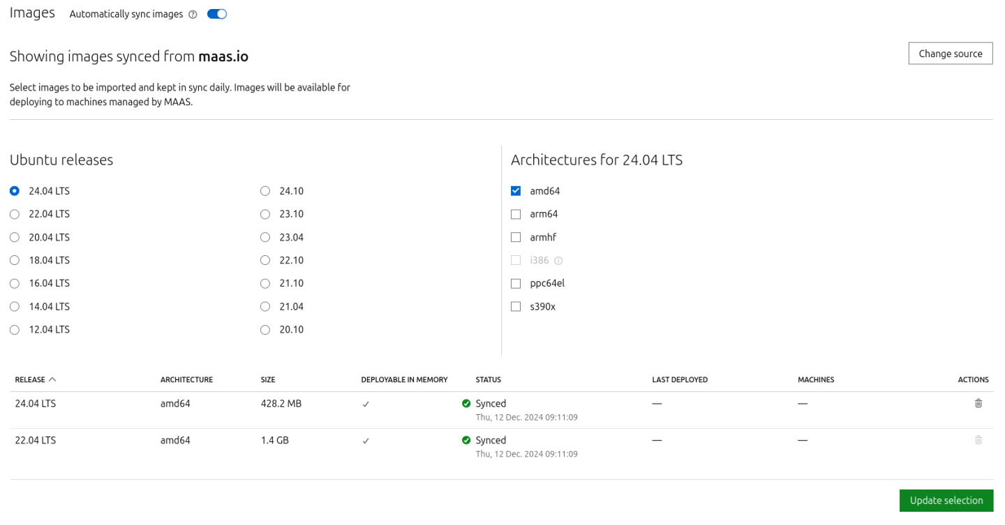
On the image selection page, select Ubuntu 24.04 LTS (amd64) and sync the image.
Import the previously generated SSH key (
id_rsa.pub) for thedepuserinto the MAAS admin user profile and finalize the setup.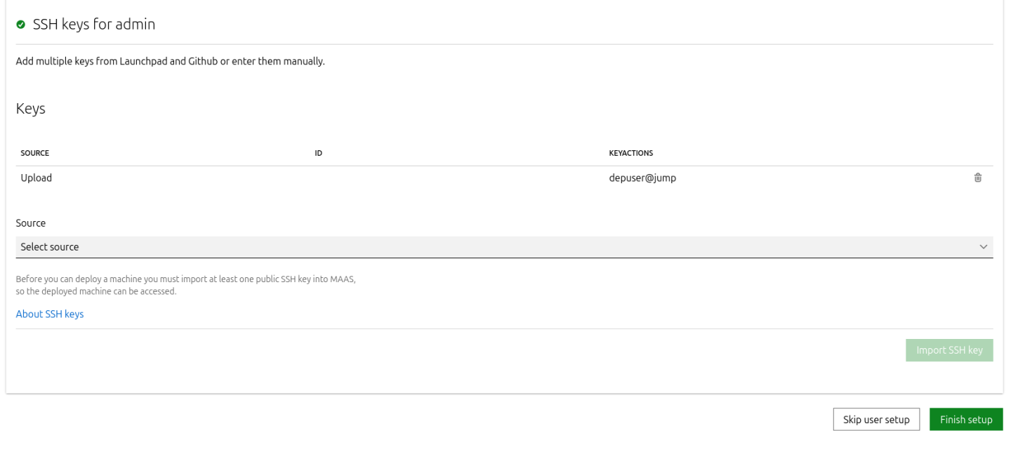
- Connect to the Jump node GUI and access the MAAS UI at
Configure DHCP snippets:
- Navigate to Settings → DHCP Snippets → Add Snippet.
Fill in the following fields:
- Name:
dpf-mgmt - Toggle on "Enabled"
- Type: IP Range
- Applies to:
10.0.110.21-10.0.110.30
- Name:
Fill in the content of the DHCP snippet field with the following (replace MAC address as appropriate with your workers MGMT interface MAC):
DHCP snippet
            # worker1
host worker1 {
   #
   # Node DHCP snippets
   #

   hardware ethernet 04:32:01:60:0d:da;
   fixed-address 10.0.110.21;
}
# worker2
host worker2 {
   #
   # Node DHCP snippets
   #

   hardware ethernet 04:32:01:5f:cb:e0;
   fixed-address 10.0.110.22;
}
# target
host target {
   #
   # Node DHCP snippets
   #

   hardware ethernet 0c:c4:7a:a4:b9:1c;
   fixed-address 10.0.110.25;
}
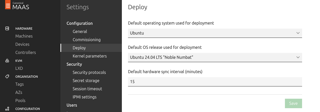
Go to Settings → Deploy, set "Default OS release" to Ubuntu 24.04 LTS Noble Numbat, and save.
- Update the DNS nameserver IP address in both the Jump and MAAS VM Netplan files from
10.0.110.254to10.0.110.252and reapply the configuration.
K8s Master VMs
Suggested specifications:
- vCPU: 8
- RAM: 16GB
- Storage: 100GB
- Network interface: Bridge device, connected to
mgmt-br
Before provisioning the Kubernetes (K8s) Master VMs with MAAS, create the required virtual disks with empty storage. Use the following one-liner to create three 100 GB QCOW2 virtual disks:
Hypervisor Console
$ for i in $(seq 1 3); do qemu-img create -f qcow2 /var/lib/libvirt/images/master$i.qcow2 100G; done
This command generates the following disks in the
/var/lib/libvirt/images/directory:master1.qcow2master2.qcow2master3.qcow2
Configure VMs in virt-manager:
Open virt-manager and create three virtual machines:
- Assign the corresponding virtual disk (
master1.qcow2,master2.qcow2, ormaster3.qcow2) to each VM. - Configure each VM with the suggested specifications (vCPU, RAM, storage, and network interface).
- Assign the corresponding virtual disk (
- During the VM setup, ensure the NIC is selected under the Boot Options tab. This ensures the VMs can PXE boot for MAAS provisioning.
- Once the configuration is complete, shut down all the VMs.
- After the VMs are created and configured, proceed to provision them via the MAAS interface. MAAS will handle the OS installation and further setup as part of the deployment process.
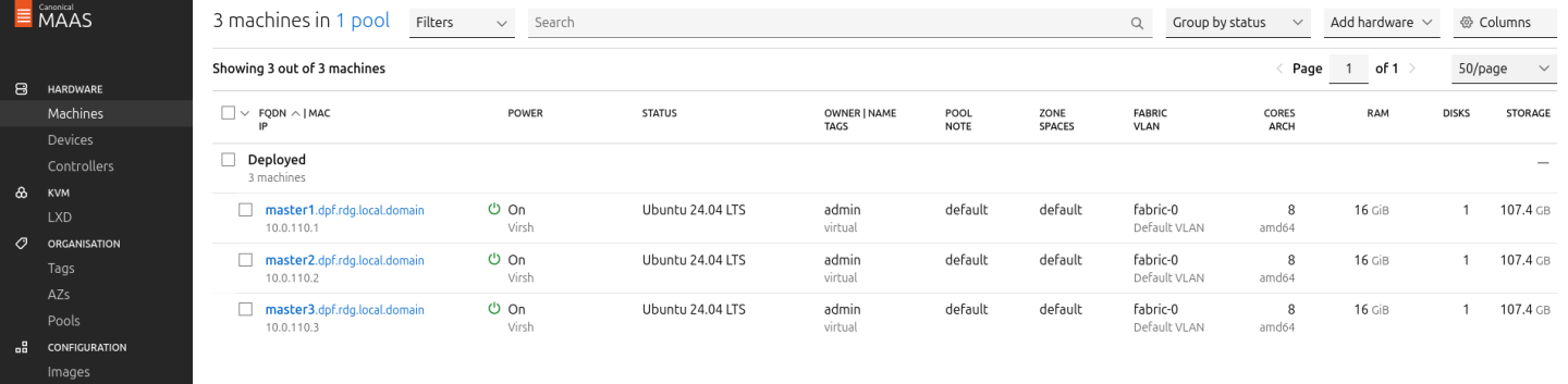
Provision Master VMs, Workers and Storage Target Nodes Using MAAS
Master VMs
Install virsh and Set Up SSH Access
SSH to the MAAS VM from the Jump node:
MaaS Console
            depuser@jump:~$ ssh maas
depuser@maas:~$ sudo -i
Install the
virshclient to communicate with the hypervisor:MaaS Console
# apt install -y libvirt-clients
Generate an SSH key for the
rootuser and copy it to the hypervisor user in thelibvirtdgroup:MaaS Console
            # ssh-keygen -t rsa
# ssh-copy-id ubuntu@<hypervisor_MGMT_IP>
Verify SSH access and
virshcommunication with the hypervisor:MaaS Console
# virsh -c qemu+ssh://ubuntu@<hypervisor_MGMT_IP>/system list --all
Expected output:
MaaS Console
             Id   Name          State
------------------------------
 1    fw     running
 2    jump   running
 3    maas   running
 -    master1       shut off
 -    master2       shut off
 -    master3       shut off
Copy the SSH key to the required MAAS directory (for snap-based installations):
MaaS Console
            # mkdir -p /var/snap/maas/current/root/.ssh
# cp .ssh/id_rsa* /var/snap/maas/current/root/.ssh/
Get MAC Addresses of the Master VMs
Retrieve the MAC addresses of the Master VMs:
MaaS Console
# for i in $(seq 1 3); do virsh -c qemu+ssh://ubuntu@<hypervisor_MGMT_IP>/system dumpxml master$i | grep 'mac address'; done
Example output:
MaaS Console
            <mac address='52:54:00:a9:9c:ef'/>
<mac address='52:54:00:19:6b:4d'/>
<mac address='52:54:00:68:39:7f'/>
Add Master VMs to MAAS
Add the Master VMs to MAAS:
InfoOnce added, MAAS will automatically start commissioning the newly added VMs (discovery and introspection).
MaaS Console
            # maas admin machines create hostname=master1 architecture=amd64/generic mac_addresses='52:54:00:a9:9c:ef' power_type=virsh power_parameters_power_address=qemu+ssh://ubuntu@<hypervisor_MGMT_IP>/system power_parameters_power_id=master1 skip_bmc_config=1 testing_scripts=none
Success.
Machine-readable output follows:
{
    "description": "",
    "status_name": "Commissioning",
...
    "status": 1,
...
    "system_id": "c3seyq",
...
    "fqdn": "master1.dpf.rdg.local.domain",
    "power_type": "virsh",
...
    "status_message": "Commissioning",
    "resource_uri": "/MAAS/api/2.0/machines/c3seyq/"
}

# maas admin machines create hostname=master2 architecture=amd64/generic mac_addresses='52:54:00:19:6b:4d' power_type=virsh power_parameters_power_address=qemu+ssh://ubuntu@<hypervisor_MGMT_IP>/system power_parameters_power_id=master2 skip_bmc_config=1 testing_scripts=none

# maas admin machines create hostname=master3 architecture=amd64/generic mac_addresses='52:54:00:68:39:7f' power_type=virsh power_parameters_power_address=qemu+ssh://ubuntu@<hypervisor_MGMT_IP>/system power_parameters_power_id=master3 skip_bmc_config=1 testing_scripts=none
Repeat the command for
master2andmaster3with their respective MAC addresses.Verify commissioning by waiting for the status to change to "Ready" in MAAS.
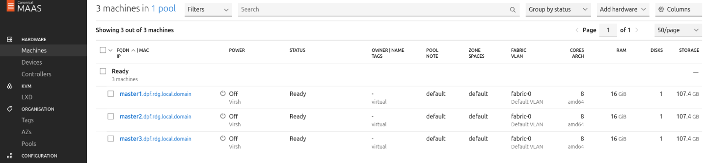
After commissioning, the next phase is the deployment (OS provisioning).
Configure OVS Bridges on Master VMs
To have persistency across reboots, create an OVS-bridge from each management interface of the master nodes and assign it a static IP address.
For each Master VM:
Create an OVS bridge in the MAAS Network tab:
- Navigate to Network → Management Interface → Create Bridge.
Configure as follows:
- Name:
brenp1s0(prefixbradded to the interface name) - Bridge Type: Open vSwitch (ovs)
- Subnet: 10.0.110.0/24
- IP Mode: Static Assign
Address: Assign
10.0.110.1formaster1,10.0.110.2formaster2, and10.0.110.3formaster3.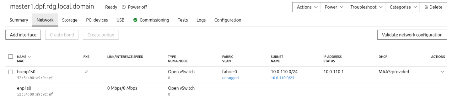
- Name:
- Save the interface settings for each VM.
Deploy Master VMs Using Cloud-Init
Use the following cloud-init script to configure the necessary software and ensure OVS bridge persistency:
NoteReplace
enp1s0andbrenp1s0in the following cloud-init with your interface names as displayed in MAAS network tab.Master nodes cloud-init
#cloud-config system_info: default_user: name: depuser passwd:
"$6$jOKPZPHD9XbG72lJ$evCabLvy1GEZ5OR1Rrece3NhWpZ2CnS0E3fu5P1VcZgcRO37e4es9gmriyh14b8Jx8gmGwHAJxs3ZEjB0s0kn/"lock_passwd:falsegroups: [adm, audio, cdrom, dialout, dip, floppy, lxd, netdev, plugdev, sudo, video] sudo: ["ALL=(ALL) NOPASSWD:ALL"] shell: /bin/bash ssh_pwauth: True package_upgrade:truepackage_reboot_if_required:truepackage_update:truepackage_upgrade:truepackages: - openvswitch-switch- nfs-common runcmd: - | UPLINK_MAC=$(cat /sys/class/net/enp1s0/address) ovs-vsctl set Bridge brenp1s0 other-config:hwaddr=$UPLINK_MAC ovs-vsctl br-set-external-id brenp1s0 bridge-id brenp1s0 -- br-set-external-id brenp1s0 bridge-uplink enp1s0Deploy the Master VMs:
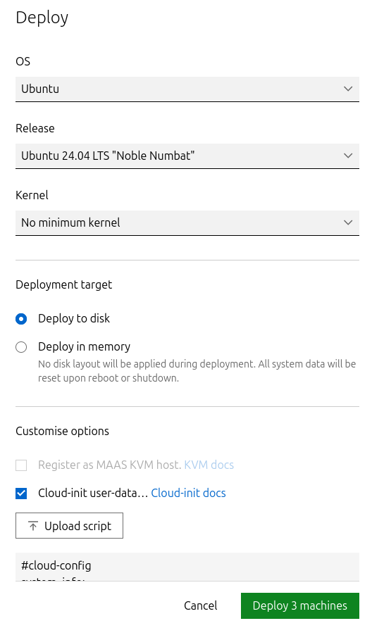
- Select all three Master VMs → Actions → Deploy.
- Toggle Cloud-init user-data and paste the cloud-init script.
Start the deployment and wait for the status to change to "Ubuntu 24.04 LTS".
Verify Deployment
SSH into the Master VMs from the Jump node:
Jump Node Console
            depuser@jump:~$ ssh master1
depuser@master1:~$
Run
sudowithout password:Master1 Console
            depuser@master1:~$ sudo -i
root@master1:~#
Verify installed packages:
Master1 Console
            root@master1:~# apt list --installed | egrep 'openvswitch-switch|nfs-common'
nfs-common/noble,now 1:2.6.4-3ubuntu5.1 amd64 [installed]
openvswitch-switch/noble-updates,now 3.3.0-1ubuntu3.1 amd64 [installed]
Check OVS bridge attributes:
Master1 Console
root@master1:~# ovs-vsctl list bridge brenp1s0
Output example:
Master1 Console
            ...
external_ids        : {bridge-id=brenp1s0, bridge-uplink=enp1s0, netplan="true", "netplan/global/set-fail-mode"=standalone, "netplan/mcast_snooping_enable"="false", "netplan/rstp_enable"="false"}
...
other_config        : {hwaddr="52:54:00:a9:9c:ef"}
...
Finalize Setup
Reboot the Master VMs to complete the provisioning:
Master1 Console
root@master1:~# reboot
Worker and Storage Target Nodes
Create Workers and Target Machines in MAAS
Add the worker nodes to MAAS using
ipmias the power type. Replace placeholders with your specific IPMI credentials and IP addresses:Kernel options for worker nodes
# maas admin machines create hostname=worker1 architecture=amd64 power_type=ipmi power_parameters_power_driver=LAN_2_0 power_parameters_power_user=<IPMI_username_worker1> power_parameters_power_pass=<IPMI_password_worker1> power_parameters_power_address=<IPMI_address_worker1>
Output example:
MaaS Console
            ...
Success.
Machine-readable output follows:
{
    "description": "",
    "status_name": "Commissioning",
...
    "status": 1,
...
    "system_id": "pbskd3",
...
    "fqdn": "worker1.dpf.rdg.local.domain",
...
    "power_type": "ipmi",
...
    "resource_uri": "/MAAS/api/2.0/machines/pbskd3/"
}
Repeat the command for
worker2andtargetwith its respective credentials:Kernel options for worker nodes
            # maas admin machines create hostname=worker2 architecture=amd64 power_type=ipmi power_parameters_power_driver=LAN_2_0 power_parameters_power_user=<IPMI_username_worker2> power_parameters_power_pass=<IPMI_password_worker2> power_parameters_power_address=<IPMI_address_worker2>
# maas admin machines create hostname=target architecture=amd64 power_type=ipmi power_parameters_power_driver=LAN_2_0 power_parameters_power_user=<IPMI_username_target> power_parameters_power_pass=<IPMI_password_target> power_parameters_power_address=<IPMI_address_target>
Once added, MAAS will automatically start commissioning the Worker and Storage Target nodes (discovery and introspection).
Adjust Network Settings
For each worker node, configure the network interfaces:
Management Adapter:
- Go to Network → Select the host management adapter (e.g.,
ens15f0) → Create Bridge - Name:
br-dpu - Bridge Type: Standard
- Subnet:
10.0.110.0/24 - IP Mode: DHCP
- Save the interface
- Go to Network → Select the host management adapter (e.g.,
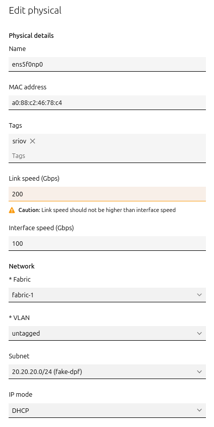
BlueField Adapter:
- Select
P0on the BlueField adapter (e.g.,ens5f0np0) → Actions → Edit Physical - Fabric:
Fabric-1 - Subnet:
20.20.20.0/24(fake-dpf) - IP Mode: DHCP
- Save the interface
- Select
Repeat these steps for the second worker node.
For Storage Target Node, configure the network interfaces:
Management Adapter:
- Go to Network → Select the host management adapter (e.g.,
ens1s0f0) → Edit Physical - Subnet:
10.0.110.0/24 - IP Mode: DHCP
- Save the interface
- Go to Network → Select the host management adapter (e.g.,
ConnectX-7 Adapter:
- Leave unchanged
Deploy Worker Nodes Using Cloud-Init
Use the following cloud-init script for deployment:
Worker node cloud-init
#cloud-config system_info: default_user: name: depuser passwd:
"$6$jOKPZPHD9XbG72lJ$evCabLvy1GEZ5OR1Rrece3NhWpZ2CnS0E3fu5P1VcZgcRO37e4es9gmriyh14b8Jx8gmGwHAJxs3ZEjB0s0kn/"lock_passwd:falsegroups: [adm, audio, cdrom, dialout, dip, floppy, lxd, netdev, plugdev, sudo, video] sudo: ["ALL=(ALL) NOPASSWD:ALL"] shell: /bin/bash ssh_pwauth:truepackage_reboot_if_required:truepackage_update:truepackage_upgrade:truepackages: - nfs-common write_files: - path: /etc/sysctl.d/99-custom-netfilter.conf owner: root:root permissions:'0644'content: | net.bridge.bridge-nf-call-iptables=0runcmd: - sysctl --system- Deploy the worker nodes by selecting the worker nodes in MAAS → Actions → Deploy → Customize options → Enable Cloud-init user-data → Paste the cloud-init script → Deploy.
Deploy Storage Target Node Using Cloud-Init
Use the following cloud-init script for deployment:
Target node cloud-init
#cloud-config users: -
default- name: depuser passwd:"$6$jOKPZPHD9XbG72lJ$evCabLvy1GEZ5OR1Rrece3NhWpZ2CnS0E3fu5P1VcZgcRO37e4es9gmriyh14b8Jx8gmGwHAJxs3ZEjB0s0kn/"lock_passwd:falsegroups: [adm, audio, cdrom, dialout, dip, floppy, lxd, netdev, plugdev, sudo, video] sudo: ["ALL=(ALL) NOPASSWD:ALL"] shell: /bin/bash ssh_pwauth:truepackage_reboot_if_required:truepackage_update:truepackage_upgrade:truepackages: - nvme-cli- Deploy the Storage Target Node by selecting the Storage Target Node in MAAS → Actions → Deploy → Customize options → Enable Cloud-init User-Data → Paste the cloud-init script → Deploy.
Manually assign an IP address to the DATA interface after node has been deployed in MAAS via netplan according to your SPDK IPAM CIDR (in our case 10.0.124.1/24)
Target node /etc/netplan/50-cloud-init.yaml
network: version:
2ethernets: # DATAinterfaceenp144s0f0np0: match: macaddress:"04:3f:72:ed:97:d6"optional:trueset-name:"enp144s0f0np0"mtu:1500addresses: -"10.0.124.1/24"nameservers: addresses: -10.0.110.252search: - dpf.rdg.local.domain enp144s0f1np1: match: macaddress:"04:3f:72:ed:97:d7"optional:trueset-name:"enp144s0f1np1"mtu:1500# Managementinterfaceenp1s0f0: match: macaddress:"0c:c4:7a:a4:b9:1c"dhcp4:trueset-name:"enp1s0f0"mtu:1500enp1s0f1: match: macaddress:"0c:c4:7a:a4:b9:1d"optional:trueset-name:"enp1s0f1"mtu:1500
Verify the Deployment
After the deployment is complete, verify that the worker nodes have been deployed successfully with the following commands:
SSH without password from the jump node:
Jump Node Console
            depuser@jump:~$ ssh worker1
depuser@worker1:~$
Run
sudowithout password:Worker1 Console
            depuser@worker1:~$ sudo -i
root@worker1:~#
Validate that the
nfs-commonpackage is installed:Worker1 Console
            root@worker1:~# apt list --installed | grep 'nfs-common'
nfs-common/noble,now 1:2.6.4-3ubuntu5.1 amd64 [installed]
br_netfiltermodule is not loaded:Worker1 Console
            root@worker1:~# lsmod | grep br_netfilter
root@worker1:~#
P0 interface has
dhcp4set totrueand does not havemtuline in thenetplanconfiguration file.Worker1 Console
            root@worker1:~# cat /etc/netplan/50-cloud-init.yaml
network:
...
		ens5f0np0:
            dhcp4: true
            match:
                macaddress: a0:88:c2:46:78:c4
            set-name: ens5f0np0
...
Finalize Deployment
Reboot ALL nodes:
Jump Node Console
root@worker1:~# reboot
The infrastructure is now ready for the K8s deployment.
Provision SPDK Target Apps on Storage Target Node
Login as root account to Storage Target Node:
Jump Node Console
            $ ssh target
$ sudo -i
Build SPDK from source (root privileges is required!):
Jump Node Console
            git clone https://github.com/spdk/spdk
cd spdk

# v24.01 is the last version that is compatible with the spdk-csi
git checkout v24.01
git submodule update --init
apt update && apt install meson python3-pyelftools -y
./scripts/pkgdep.sh --rdma
./configure --with-rdma
make
Run SPDK target:
Jump Node Console
            # Get all nvme devices

lshw -c storage -businfo

Bus info          Device         Class          Description
===========================================================
pci@0000:08:00.0                 storage        PCIe Data Center SSD
pci@0000:00:11.4                 storage        C610/X99 series chipset sSATA Controller [AHCI mode]
pci@0000:00:1f.2                 storage        C610/X99 series chipset 6-Port SATA Controller [AHCI mode]
pci@0000:81:00.0  scsi4          storage        MegaRAID SAS-3 3108 [Invader]

# Start target
scripts/setup.sh
build/bin/nvmf_tgt &

# Add bdevs with nvme backend
scripts/rpc.py bdev_nvme_attach_controller -b Nvme0 -t PCIe -a 0000:08:00.0

# Add logical volume store on base bdev
scripts/rpc.py bdev_lvol_create_lvstore Nvme0n1 lvs0

# Display current logical volume list
scripts/rpc.py bdev_lvol_get_lvstores

scripts/rpc_http_proxy.py 10.0.110.25 8000 exampleuser examplepassword &
- SPDK target is ready.
K8s Cluster Deployment and Configuration
Kubespray Deployment and Configuration
In this solution, the Kubernetes (K8s) cluster is deployed using a modified version of Kubespray (based on tag v2.26.0) with a non-root depuser account from the Jump Node. The modifications in Kubespray are designed to meet the DPF prerequisites, as described in the User Manual and to facilitate cluster deployment and scaling.
- Download the modified Kubespray archive: modified_kubespray_v2.26.0.tar.gz.
Extract the contents and navigate to the extracted directory:
Jump Node Console
            $ tar -xzf /home/depuser/modified_kubespray_v2.26.0.tar.gz
$ cd kubespray/
depuser@jump:~/kubespray$
Set the K8s API VIP address and DNS record. Replace it with your own IP address and DNS record if different:
Jump Node Console
            depuser@jump:~/kubespray$ sed -i '/  #kube_vip_address:/s/.*/kube_vip_address: 10.0.110.10/' inventory/mycluster/group_vars/k8s_cluster/addons.yml
depuser@jump:~/kubespray$ sed -i '/apiserver_loadbalancer_domain_name:/s/.*/apiserver_loadbalancer_domain_name: "kube-vip.dpf.rdg.local.domain"/' roles/kubespray-defaults/defaults/main/main.yml
Install the necessary dependencies and set up the Python virtual environment:
Jump Node Console
            depuser@jump:~/kubespray$ sudo apt -y install python3-pip jq python3.12-venv
depuser@jump:~/kubespray$ python3 -m venv .venv
depuser@jump:~/kubespray$ source .venv/bin/activate
(.venv) depuser@jump:~/kubespray$ python3 -m pip install --upgrade pip
(.venv) depuser@jump:~/kubespray$ pip install -U -r requirements.txt
(.venv) depuser@jump:~/kubespray$ pip install ruamel-yaml
Review and edit the
inventory/mycluster/hosts.yamlfile to define the cluster nodes. The following is the configuration for this deployment:NoteAll of the nodes are already labeled and annotated as per the DPF User Manual prerequisites.
The
kube_nodegroup is marked with # to deploy only the cluster with control plane nodes at the beginning. (Worker nodes will be added after the various components necessary for the DPF system are installed).
inventory/mycluster/hosts.yaml
all: hosts: master1: ansible_host:
10.0.110.1ip:10.0.110.1access_ip:10.0.110.1node_labels:"k8s.ovn.org/zone-name":"master1"master2: ansible_host:10.0.110.2ip:10.0.110.2access_ip:10.0.110.2node_labels:"k8s.ovn.org/zone-name":"master2"master3: ansible_host:10.0.110.3ip:10.0.110.3access_ip:10.0.110.3node_labels:"k8s.ovn.org/zone-name":"master3"worker1: ansible_host:10.0.110.21ip:10.0.110.21access_ip:10.0.110.21node_labels:"node-role.kubernetes.io/worker":"""k8s.ovn.org/dpu-host":"""k8s.ovn.org/zone-name":"worker1"node_annotations:"k8s.ovn.org/remote-zone-migrated":"worker1"worker2: ansible_host:10.0.110.22ip:10.0.110.22access_ip:10.0.110.22node_labels:"node-role.kubernetes.io/worker":"""k8s.ovn.org/dpu-host":"""k8s.ovn.org/zone-name":"worker2"node_annotations:"k8s.ovn.org/remote-zone-migrated":"worker2"children: kube_control_plane: hosts: master1: master2: master3: kube_node: hosts: worker1: worker2: etcd: hosts: master1: master2: master3: k8s_cluster: children: kube_control_plane: # kube_node:
Deploying Cluster Using Kubespray Ansible Playbook
Run the following command from the Jump Node to initiate deployment:
NoteEnsure you are in the Python virtual environment (
.venv) when running the command.Jump Node Console
(.venv) depuser@jump:~/kubespray$ ansible-playbook -i inventory/mycluster/hosts.yaml --become --become-user=root cluster.yml
It takes a while for this deployment to complete. Make sure there are no errors. A successful result example:
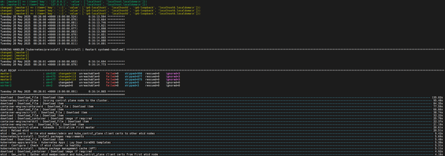 Tip
TipIt is recommended to keep the shell from which Kubespray was running open; later on it will be useful when performing a cluster scale-out to add the worker nodes.
K8s Deployment Verification
To simplify managing the K8s cluster from the Jump Host, set up kubectl with bash auto-completion.
Copy
kubectland the kubeconfig file frommaster1to the Jump Host:Jump Node Console
            ## Connect to master1
depuser@jump:~$ ssh master1
depuser@master1:~$ cp /usr/local/bin/kubectl /tmp/
depuser@master1:~$ sudo cp /root/.kube/config /tmp/kube-config
depuser@master1:~$ sudo chmod 644 /tmp/kube-config
In another terminal tab, copy the files to the Jump Host:
Jump Node Console
            depuser@jump:~$ scp master1:/tmp/kubectl /tmp/
depuser@jump:~$ sudo chown root:root /tmp/kubectl
depuser@jump:~$ sudo mv /tmp/kubectl /usr/local/bin/
depuser@jump:~$ mkdir -p ~/.kube
depuser@jump:~$ scp master1:/tmp/kube-config ~/.kube/config
depuser@jump:~$ chmod 600 ~/.kube/config
Enable bash auto-completion for
kubectl:Verify if bash-completion is installed:
Jump Node Console
depuser@jump:~$ type _init_completion
If installed, the output includes:
Jump Node Console
_init_completion is a function
If bash-completion has not been installed, install it:
Jump Node Console
depuser@jump:~$ sudo apt install -y bash-completion
Set up the
kubectlcompletion script:Jump Node Console
            depuser@jump:~$ kubectl completion bash | sudo tee /etc/bash_completion.d/kubectl > /dev/null
depuser@jump:~$ bash
Check the status of the nodes in the cluster:
Jump Node Console
depuser@jump:~$ kubectl get nodes
Expected output:
NoteNodes will be in the
NotReadystate because the deployment did not include CNI components.Jump Node Console
            NAME      STATUS     ROLES           AGE   VERSION
master1   NotReady   control-plane   42m   v1.30.4
master2   NotReady   control-plane   41m   v1.30.4
master3   NotReady   control-plane   41m   v1.30.4
Check the pods in all namespaces:
Jump Node Console
depuser@jump:~$ kubectl get pods -A
Expected output:
Notecorednsanddns-autoscalerpods will be in thePendingstate due to the absence of CNI components.Jump Node Console
            NAMESPACE     NAME                              READY   STATUS    RESTARTS   AGE
kube-system   coredns-776bb9db5d-ndr7j          0/1     Pending   0          41m
kube-system   dns-autoscaler-6ffb84bd6-xj9bv    0/1     Pending   0          41m
kube-system   kube-apiserver-master1            1/1     Running   0          43m
kube-system   kube-apiserver-master2            1/1     Running   0          42m
kube-system   kube-apiserver-master3            1/1     Running   0          42m
kube-system   kube-controller-manager-master1   1/1     Running   1          43m
kube-system   kube-controller-manager-master2   1/1     Running   1          42m
kube-system   kube-controller-manager-master3   1/1     Running   1          42m
kube-system   kube-scheduler-master1            1/1     Running   1          43m
kube-system   kube-scheduler-master2            1/1     Running   1          42m
kube-system   kube-scheduler-master3            1/1     Running   1          42m
kube-system   kube-vip-master1                  1/1     Running   0          43m
kube-system   kube-vip-master2                  1/1     Running   0          42m
kube-system   kube-vip-master3                  1/1     Running   0          42m
DPF Installation
Software Prerequisites and Required Variables
Start by installing the remaining software prerequisites.
Jump Node Console
            ## Connect to master1 to copy helm client utility that was installed during kubespray deployment
$ depuser@jump:~$ ssh master1
depuser@master1:~$ cp /usr/local/bin/helm /tmp/

## In another tab
depuser@jump:~$ scp master1:/tmp/helm /tmp/
depuser@jump:~$ sudo chown root:root /tmp/helm
depuser@jump:~$ sudo mv /tmp/helm /usr/local/bin/

## Verify that envsubst utility is installed
depuser@jump:~$ which envsubst
/usr/bin/envsubst
Proceed to clone the doca-platform Git repository (make sure to use tag v25.4.0):
Jump Node Console
            $ git clone https://github.com/NVIDIA/doca-platform.git
$ cd doca-platform
$ git checkout v25.4.0
Change the directory to the location of the HBN-OVN usecase, from where all the commands are run :
Jump Node Console
$ cd docs/public/user-guides/hbn_ovn
Remove unused components of the HBN-OVN deployment usecase :
Jump Node Console
$ rm -rf manifests/05* manifests/06*
Download the hbn-ovn-snap.zip file with the required YAML deployment files for this guide, then unarchive it:
Jump Node Console
            $ unzip hbn-ovn-snap.zip

$ ls -Ad manifests/*
manifests/00-high-speed-switch-configuration
manifests/01-cni-installation
manifests/02-dpf-operator-installation
manifests/03-dpf-system-installation
manifests/04-enable-accelerated-cni
manifests/05-dpudeployment-installation
manifests/06-test-traffic
Use the export_vars.env file to define the required variables for the installation:
WarningReplace the values for the variables in the following file with the values that fit your setup. Specifically, pay attention to
DPU_P0,DPU_P0_VF1andDPUCLUSTER_INTERFACE.
export_vars.env
## IP Address for the Kubernetes API server of the target cluster on which DPF is installed.## This should never include a scheme or a port.## e.g. 10.10.10.10exportTARGETCLUSTER_API_SERVER_HOST=10.0.110.10## Port for the Kubernetes API server of the target cluster on which DPF is installed.exportTARGETCLUSTER_API_SERVER_PORT=6443## IP address range for hosts in the target cluster on which DPF is installed.## This is a CIDR in the form e.g. 10.10.10.0/24exportTARGETCLUSTER_NODE_CIDR=10.0.110.0/24## Virtual IP used by the load balancer for the DPU Cluster. Must be a reserved IP from the management subnet and not allocated by DHCP.exportDPUCLUSTER_VIP=10.0.110.200## DPU_P0 is the name of the first port of the DPU. This name must be the same on all worker nodes.exportDPU_P0=ens5f0np0## DPU_P0_VF1 is the name of the second Virtual Function (VF) of the first port of the DPU. This name must be the same on all worker nodes.exportDPU_P0_VF1=ens5f0v1## Interface on which the DPUCluster load balancer will listen. Should be the management interface of the control plane node.exportDPUCLUSTER_INTERFACE=brenp1s0## IP address to the NFS server used as storage for the BFB.exportNFS_SERVER_IP=10.0.110.253## The repository URL for the NVIDIA Helm chart registry.## Usually this is the NVIDIA Helm NGC registry. For development purposes, this can be set to a different repository.exportNGC_HELM_REGISTRY_REPO_URL=https://helm.ngc.nvidia.com/nvidia/doca## The repository URL for the HBN container image.## Usually this is the NVIDIA NGC registry. For development purposes, this can be set to a different repository.exportHBN_NGC_IMAGE_URL=nvcr.io/nvidia/doca/doca_hbn## The repository URL for the OVN Kubernetes Helm chart.## Usually this is the NVIDIA GHCR repository. For development purposes, this can be set to a different repository.exportOVN_KUBERNETES_REPO_URL=oci://ghcr.io/nvidia## POD_CIDR is the CIDR used for pods in the target Kubernetes cluster.exportPOD_CIDR=10.233.64.0/18## SERVICE_CIDR is the CIDR used for services in the target Kubernetes cluster.## This is a CIDR in the form e.g. 10.10.10.0/24exportSERVICE_CIDR=10.233.0.0/18## The DPF REGISTRY is the Helm repository URL for the DPF Operator.## Usually this is the GHCR registry. For development purposes, this can be set to a different repository.exportREGISTRY=https://helm.ngc.nvidia.com/nvidia/doca## The DPF TAG is the version of the DPF components which will be deployed in this guide.exportTAG=v25.4.0## URL to the BFB used in the `bfb.yaml` and linked by the DPUSet.exportBLUEFIELD_BITSTREAM="https://content.mellanox.com/BlueField/BFBs/Ubuntu22.04/bf-bundle-3.0.0-135_25.04_ubuntu-22.04_prod.bfb"Export environment variables for the installation:
Jump Node Console
$ source export_vars.env
CNI Installation
OVN Kubernetes is used as the primary CNI for the cluster. On worker nodes, the primary CNI will be accelerated by offloading work to the DPU. On control plane nodes, OVN Kubernetes will run without offloading.
Create the NS for the CNI:
Jump Node Console
$ kubectl create ns ovn-kubernetes
Install the OVN Kubernetes CNI components from the helm chart, while substituting the environment variables with the ones we defined before.
manifests/01-cni-installation/helm-values/ovn-kubernetes.yml
commonManifests: enabled:
truenodeWithoutDPUManifests: enabled:truecontrolPlaneManifests: enabled:truenodeWithDPUManifests: enabled:truenodeMgmtPortNetdev: $DPU_P0_VF1 dpuServiceAccountNamespace: dpf-operator-system gatewayOpts: --gateway-interface=$DPU_P0 ## NotethisCIDR is followed by a trailing /24which informs OVN Kubernetes on how to split the CIDR per node. podNetwork: $POD_CIDR/24serviceNetwork: $SERVICE_CIDR k8sAPIServer: https://$TARGETCLUSTER_API_SERVER_HOST:$TARGETCLUSTER_API_SERVER_PORTRun the following command:
Jump Node Console
            $ envsubst < manifests/01-cni-installation/helm-values/ovn-kubernetes.yml | helm upgrade --install -n ovn-kubernetes ovn-kubernetes ${OVN_KUBERNETES_REPO_URL}/ovn-kubernetes-chart --version $TAG --values -

Release "ovn-kubernetes" does not exist. Installing it now.
Pulled: ghcr.io/nvidia/ovn-kubernetes-chart:v25.4.0
Digest: sha256:bce61b35ab485f06924681c5c906bfc0ab0065ac94830c6c036418e1edf995b3
NAME: ovn-kubernetes
LAST DEPLOYED: Tue May 20 08:51:29 2025
NAMESPACE: ovn-kubernetes
STATUS: deployed
REVISION: 1
TEST SUITE: None
Verify the CNI installation:
NoteThe following verification commands may need to be run multiple times to ensure the condition is met.
Jump Node Console
            $ kubectl wait --for=condition=ready --namespace ovn-kubernetes pods --all --timeout=300s
pod/ovnkube-control-plane-7b9869d9bd-jd94x condition met
pod/ovnkube-node-2bpmd condition met
pod/ovnkube-node-d4mb8 condition met
pod/ovnkube-node-stxlv condition met

$ kubectl wait --for=condition=ready nodes --all
node/master1 condition met
node/master2 condition met
node/master3 condition met

$ kubectl wait --for=condition=ready --namespace kube-system pods --all
pod/coredns-776bb9db5d-ndr7j condition met
pod/coredns-776bb9db5d-w499z condition met
pod/dns-autoscaler-6ffb84bd6-xj9bv condition met
pod/kube-apiserver-master1 condition met
pod/kube-apiserver-master2 condition met
pod/kube-apiserver-master3 condition met
pod/kube-controller-manager-master1 condition met
pod/kube-controller-manager-master2 condition met
pod/kube-controller-manager-master3 condition met
pod/kube-scheduler-master1 condition met
pod/kube-scheduler-master2 condition met
pod/kube-scheduler-master3 condition met
pod/kube-vip-master1 condition met
pod/kube-vip-master2 condition met
pod/kube-vip-master3 condition met
DPF Operator Installation
Cert-manager Installation
Cert-manager is a powerful and extensible X.509 certificate controller for Kubernetes workloads. It obtains certificates from a variety of Issuers, both popular public Issuers as well as private ones. It ensures the certificates are valid and up-to-date and attempts to renew certificates at a configured time before expiry.
In this deployment, it's a prerequisite used to provide certificates for webhooks utilized by DPF and its dependencies.
Create the NS for the operator:
Jump Node Console
$ kubectl create ns dpf-operator-system
Install Cert-manager using helm.
The following values are used for helm chart installation:
manifests/02-dpf-operator-installation/helm-values/cert-manager.yml
startupapicheck: enabled:
falsecrds: enabled:trueaffinity: nodeAffinity: requiredDuringSchedulingIgnoredDuringExecution: nodeSelectorTerms: - matchExpressions: - key: node-role.kubernetes.io/master operator: Exists - matchExpressions: - key: node-role.kubernetes.io/control-plane operator: Exists tolerations: - operator: Exists effect: NoSchedule key: node-role.kubernetes.io/control-plane - operator: Exists effect: NoSchedule key: node-role.kubernetes.io/master cainjector: affinity: nodeAffinity: requiredDuringSchedulingIgnoredDuringExecution: nodeSelectorTerms: - matchExpressions: - key: node-role.kubernetes.io/master operator: Exists - matchExpressions: - key: node-role.kubernetes.io/control-plane operator: Exists tolerations: - operator: Exists effect: NoSchedule key: node-role.kubernetes.io/control-plane - operator: Exists effect: NoSchedule key: node-role.kubernetes.io/master webhook: affinity: nodeAffinity: requiredDuringSchedulingIgnoredDuringExecution: nodeSelectorTerms: - matchExpressions: - key: node-role.kubernetes.io/master operator: Exists - matchExpressions: - key: node-role.kubernetes.io/control-plane operator: Exists tolerations: - operator: Exists effect: NoSchedule key: node-role.kubernetes.io/control-plane - operator: Exists effect: NoSchedule key: node-role.kubernetes.io/masterRun the following commands:
Jump Node Console
            $ helm repo add jetstack https://charts.jetstack.io --force-update
$ helm upgrade --install --create-namespace --namespace cert-manager cert-manager jetstack/cert-manager --version v1.16.1 -f ./manifests/02-dpf-operator-installation/helm-values/cert-manager.yml

Release "cert-manager" does not exist. Installing it now.
NAME: cert-manager
LAST DEPLOYED: Tue May 20 12:59:30 2025
NAMESPACE: cert-manager
STATUS: deployed
REVISION: 1
TEST SUITE: None
NOTES:
cert-manager v1.16.1 has been deployed successfully!
Verify that all pods in the cert-manager namespace are in a ready state:
Jump Node Console
            $ kubectl wait --for=condition=ready --namespace cert-manager pods --all
pod/cert-manager-6ffdf6c5f8-tgv69 condition met
pod/cert-manager-cainjector-66b8577665-fbr5h condition met
pod/cert-manager-webhook-5cb94cb7b6-hb29q condition met
Install a CSI to back the DPUCluster etcd
Download a local-path-provisioner helm chart to your current working directory and create a NS for it:
Jump Node Console
            $ curl https://codeload.github.com/rancher/local-path-provisioner/tar.gz/v0.0.30 | tar -xz --strip=3 local-path-provisioner-0.0.30/deploy/chart/local-path-provisioner/
$ kubectl create ns local-path-provisioner
Use the following values are used for the installation:
manifests/02-dpf-operator-installation/helm-values/local-path-provisioner.yml
            tolerations:
  - operator: Exists
    effect: NoSchedule
    key: node-role.kubernetes.io/control-plane
  - operator: Exists
    effect: NoSchedule
    key: node-role.kubernetes.io/master
Run the following command:
Jump Node Console
            $ helm install -n local-path-provisioner local-path-provisioner ./local-path-provisioner --version 0.0.30 -f ./manifests/02-dpf-operator-installation/helm-values/local-path-provisioner.yml

NAME: local-path-provisioner
LAST DEPLOYED: Tue May 20 13:01:40 2025
NAMESPACE: local-path-provisioner
STATUS: deployed
REVISION: 1
TEST SUITE: None
NOTES:
...
Ensure that the pod in local-path-provisioner namespace is in ready state:
Jump Node Console
            $ kubectl wait --for=condition=ready --namespace local-path-provisioner pods --all
pod/local-path-provisioner-75f649c47c-qb5w7 condition met
Create Storage Required by the DPF Operator
The following YAML files define storage (for the BFB image) that are required by the DPF operator.
manifests/02-dpf-operator-installation/nfs-storage-for-bfb-dpf-ga.yaml
            ---
apiVersion: v1
kind: PersistentVolume
metadata:
  name: bfb-pv
spec:
  capacity:
    storage: 10Gi
  volumeMode: Filesystem
  accessModes:
    - ReadWriteMany
  nfs:
    path: /mnt/dpf_share/bfb
    server: $NFS_SERVER_IP
  persistentVolumeReclaimPolicy: Delete
---
apiVersion: v1
kind: PersistentVolumeClaim
metadata:
  name: bfb-pvc
  namespace: dpf-operator-system
spec:
  accessModes:
  - ReadWriteMany
  resources:
    requests:
      storage: 10Gi
  volumeMode: Filesystem
Run the following command to substitute the environment variables using
envsubstand apply the YAML files:Jump Node Console
$ cat manifests/02-dpf-operator-installation/*.yaml | envsubst | kubectl apply -f -
DPF Operator Deployment
The DPF Operator helm values are detailed in the following YAML file:
manifests/02-dpf-operator-installation/helm-values/dpf-operator.yml
kamaji-etcd: persistentVolumeClaim: storageClassName: local-path node-feature-discovery: worker: extraEnvs: - name:
"KUBERNETES_SERVICE_HOST"value:"$TARGETCLUSTER_API_SERVER_HOST"- name:"KUBERNETES_SERVICE_PORT"value:"$TARGETCLUSTER_API_SERVER_PORT"Run the following command to substitute the environment variables and install the DPF Operator:
Jump Node Console
            $ helm repo add --force-update dpf-repository ${REGISTRY}
$ helm repo update
$ envsubst < ./manifests/02-dpf-operator-installation/helm-values/dpf-operator.yml | helm upgrade --install -n dpf-operator-system dpf-operator dpf-repository/dpf-operator --version=$TAG --values -

Release "dpf-operator" does not exist. Installing it now.
NAME: dpf-operator
LAST DEPLOYED: Tue May 20 13:18:58 2025
NAMESPACE: dpf-operator-system
STATUS: deployed
REVISION: 1
TEST SUITE: None
Verify the DPF Operator installation by ensuring the deployment is available, and that all pods are in a ready:
NoteThe following verification commands may need to be run multiple times to ensure the conditions are met.
Jump Node Console
            $ kubectl rollout status deployment --namespace dpf-operator-system dpf-operator-controller-manager
deployment "dpf-operator-controller-manager" successfully rolled out

$ kubectl wait --for=condition=ready --namespace dpf-operator-system pods --all
pod/dpf-operator-argocd-application-controller-0 condition met
pod/dpf-operator-argocd-applicationset-controller-84d86b665f-fqd6x condition met
pod/dpf-operator-argocd-redis-584fbbf667-zbhcb condition met
pod/dpf-operator-argocd-repo-server-6bff769f95-2cjgd condition met
pod/dpf-operator-argocd-server-54fcf54589-6cvqf condition met
pod/dpf-operator-controller-manager-54f76799c5-j4dcz condition met
pod/dpf-operator-kamaji-6dcf4ccdfd-lsgvd condition met
pod/dpf-operator-kamaji-etcd-0 condition met
pod/dpf-operator-kamaji-etcd-1 condition met
pod/dpf-operator-kamaji-etcd-2 condition met
pod/dpf-operator-maintenance-operator-7776bb95d-vnh5k condition met
pod/dpf-operator-node-feature-discovery-gc-545bdbf8df-q68wp condition met
pod/dpf-operator-node-feature-discovery-master-7df7dc844c-p64zz condition met
DPF System Installation
This section involves creating the DPF system components and some basic infrastructure required for a functioning DPF-enabled cluster.
The following YAML files define the DPFOperatorConfig to install the DPF System components. They also define the DPUCluster to serve as the Kubernetes control plane for the DPU nodes.
manifests/03-dpf-system-installation/operatorconfig.yaml
--- apiVersion: operator.dpu.nvidia.com/v1alpha1 kind: DPFOperatorConfig metadata: name: dpfoperatorconfig namespace: dpf-operator-system spec: overrides: kubernetesAPIServerVIP: $TARGETCLUSTER_API_SERVER_HOST kubernetesAPIServerPort: $TARGETCLUSTER_API_SERVER_PORT provisioningController: bfbPVCName:
"bfb-pvc"dmsTimeout:900kamajiClusterManager: disable:falsemanifests/03-dpf-system-installation/dpucluster.yaml
--- apiVersion: provisioning.dpu.nvidia.com/v1alpha1 kind: DPUCluster metadata: name: dpu-cplane-tenant1 namespace: dpu-cplane-tenant1 spec: type: kamaji maxNodes:
10version: v1.30.2clusterEndpoint: # deploy keepalived instances on the nodes that match the given nodeSelector. keepalived: #interfaceon which keepalived will listen. Should be the oobinterfaceof the control plane node.interface: $DPUCLUSTER_INTERFACE # Virtual IP reservedforthe DPU Cluster load balancer. Must not be allocatable by DHCP. vip: $DPUCLUSTER_VIP # virtualRouterID must be in range [1,255], make sure the given virtualRouterID does not duplicate with any existing keepalived process running on the host virtualRouterID:126nodeSelector: node-role.kubernetes.io/control-plane:""Create namespace (NS) for the Kubernetes control plane of the DPU nodes:
Jump Node Console
$ kubectl create ns dpu-cplane-tenant1
Apply the previous YAML files:
Jump Node Console
$ cat manifests/03-dpf-system-installation/*.yaml | envsubst | kubectl apply -f -
Verify the DPF system by ensuring that the provisioning and DPUService controller manager deployments are available. Also confirm that all other deployments in the DPF Operator system are available and that the DPUCluster is ready for nodes to join.
Jump Node Console
            $ kubectl rollout status deployment --namespace dpf-operator-system dpf-provisioning-controller-manager dpuservice-controller-manager
deployment "dpf-provisioning-controller-manager" successfully rolled out
deployment "dpuservice-controller-manager" successfully rolled out

$ kubectl rollout status deployment --namespace dpf-operator-system
deployment "dpf-operator-argocd-applicationset-controller" successfully rolled out
deployment "dpf-operator-argocd-redis" successfully rolled out
deployment "dpf-operator-argocd-repo-server" successfully rolled out
deployment "dpf-operator-argocd-server" successfully rolled out
deployment "dpf-operator-controller-manager" successfully rolled out
deployment "dpf-operator-kamaji" successfully rolled out
deployment "dpf-operator-maintenance-operator" successfully rolled out
deployment "dpf-operator-node-feature-discovery-gc" successfully rolled out
deployment "dpf-operator-node-feature-discovery-master" successfully rolled out
deployment "dpf-provisioning-controller-manager" successfully rolled out
deployment "dpuservice-controller-manager" successfully rolled out
deployment "kamaji-cm-controller-manager" successfully rolled out

$ kubectl wait --for=condition=ready --namespace dpu-cplane-tenant1 dpucluster --all
dpucluster.provisioning.dpu.nvidia.com/dpu-cplane-tenant1 condition met
Install Components to Enable Accelerated CNI Nodes
OVN Kubernetes accelerates traffic by attaching a VF to each pod using the primary CNI. This VF offloads flows to the DPU, and this section details the components needed to connect pods to the offloaded OVN Kubernetes CNI.
Install Multus and SRIOV Network Operator using NVIDIA Network Operator
Add the NVIDIA Network Operator Helm repository:
Jump Node Console
$ helm repo add nvidia https://helm.ngc.nvidia.com/nvidia --force-update
The following
network-operator.yamlvalues file will be applied:manifests/04-enable-accelerated-cni/helm-values/network-operator.yml
nfd: enabled:
falsedeployNodeFeatureRules:falsesriovNetworkOperator: enabled:truesriov-network-operator: operator: affinity: nodeAffinity: requiredDuringSchedulingIgnoredDuringExecution: nodeSelectorTerms: - matchExpressions: - key: node-role.kubernetes.io/master operator: Exists - matchExpressions: - key: node-role.kubernetes.io/control-plane operator: Exists crds: enabled:truesriovOperatorConfig: deploy:trueconfigDaemonNodeSelector:nulloperator: affinity: nodeAffinity: requiredDuringSchedulingIgnoredDuringExecution: nodeSelectorTerms: - matchExpressions: - key: node-role.kubernetes.io/master operator: Exists - matchExpressions: - key: node-role.kubernetes.io/control-plane operator: ExistsDeploy the operator:
Jump Node Console
            $ helm upgrade --no-hooks --install --create-namespace --namespace nvidia-network-operator network-operator nvidia/network-operator --version 24.7.0 -f ./manifests/04-enable-accelerated-cni/helm-values/network-operator.yml

Release "network-operator" does not exist. Installing it now.
NAME: network-operator
LAST DEPLOYED: Tue May 20 13:36:57 2025
NAMESPACE: nvidia-network-operator
STATUS: deployed
REVISION: 1
TEST SUITE: None
NOTES:
...
Ensure all the pods in nvidia-network-operator namespace are ready:
Jump Node Console
            $ kubectl wait --for=condition=ready --namespace nvidia-network-operator pods --all
pod/network-operator-7bc7b45d67-xk2fl condition met
pod/network-operator-sriov-network-operator-86c9cd4899-6hlzd condition met
Install OVN Kubernetes resource injection webhook
The OVN Kubernetes resource injection webhook is added to each pod scheduled to a worker node that requests a VF and a Network Attachment Definition. This webhook is part of the same helm chart as the other components of the OVN Kubernetes CNI. It is installed by modifying the existing helm deployment to include the webhook component.
The following
ovn-kubernetes.yamlvalues file will be applied:manifests/04-enable-accelerated-cni/helm-values/ovn-kubernetes.yml
            ovn-kubernetes-resource-injector:
  ## Enable the ovn-kubernetes-resource-injector
  enabled: true
Run the following command:
Jump Node Console
            $ envsubst < manifests/04-enable-accelerated-cni/helm-values/ovn-kubernetes.yml | helm upgrade --install -n ovn-kubernetes ovn-kubernetes-resource-injector ${OVN_KUBERNETES_REPO_URL}/ovn-kubernetes-chart --version $TAG --values -

Release "ovn-kubernetes-resource-injector" does not exist. Installing it now.
Pulled: ghcr.io/nvidia/ovn-kubernetes-chart:v25.4.0
Digest: sha256:bce61b35ab485f06924681c5c906bfc0ab0065ac94830c6c036418e1edf995b3
NAME: ovn-kubernetes-resource-injector
LAST DEPLOYED: Tue May 20 13:41:38 2025
NAMESPACE: ovn-kubernetes
STATUS: deployed
REVISION: 1
TEST SUITE: None
Verify that the resource injector deployment has been successfully rolled out.
Jump Node Console
            $ kubectl rollout status deployment --namespace ovn-kubernetes ovn-kubernetes-ovn-kubernetes-resource-injector
deployment "ovn-kubernetes-ovn-kubernetes-resource-injector" successfully rolled out
Apply NicClusterPolicy and SriovNetworkNodePolicy
Apply the following NicClusterPolicy and SriovNetworkNodePolicy configuration files should be applied.
manifests/04-enable-accelerated-cni/nic_cluster_policy.yaml
--- apiVersion: mellanox.com/v1alpha1 kind: NicClusterPolicy metadata: name: nic-cluster-policy spec: secondaryNetwork: multus: image: multus-cni imagePullSecrets: [] repository: ghcr.io/k8snetworkplumbingwg version: v3.
9.3manifests/04-enable-accelerated-cni/sriov_network_operator_policy.yaml
--- apiVersion: sriovnetwork.openshift.io/v1 kind: SriovNetworkNodePolicy metadata: name: bf3-p0-vfs namespace: nvidia-network-operator spec: mtu:
1500nicSelector: deviceID:"a2dc"vendor:"15b3"pfNames: - $DPU_P0#2-45nodeSelector: node-role.kubernetes.io/worker:""numVfs:46resourceName: bf3-p0-vfs isRdma:trueexternallyManaged:truedeviceType: netdevice linkType: ethApply those configuration files:
Jump Node Console
$ cat manifests/04-enable-accelerated-cni/*.yaml | envsubst | kubectl apply -f -
Verify the DPF system by ensuring that the following DaemonSets were successfully rolled out:
Jump Node Console
            $ kubectl rollout status daemonset --namespace nvidia-network-operator kube-multus-ds sriov-network-config-daemon sriov-device-plugin
daemon set "kube-multus-ds" successfully rolled out
daemon set "sriov-network-config-daemon" successfully rolled out
daemon set "sriov-device-plugin" successfully rolled out
DPU Provisioning and Service Installation
Provisioning limitations
NoteThe SPDK CSI image and helm chart are not provided as part of the DPF release. You need to build them following the instructions in dpuservices/storage/examples/spdk-csi/README.md. After building the image and chart, replace the placeholder values (such as
example.com/spdk-csi,oci://example.com, etc.) in the following SPDK CSI configuration examples with your actual repository locations and version information.Before deploying the objects under the
manifests/05-dpudeployment-installationdirectory, a few adjustments need to be made.Review
dpudeployment.yamlto reference the DPUFlavor suited for SNAP:manifests/05-dpudeployment-installation/dpudeployment.yaml
--- apiVersion: svc.dpu.nvidia.com/v1alpha1 kind: DPUDeployment metadata: name: ovn-hbn-snap namespace: dpf-operator-system spec: dpus: bfb: bf-bundle flavor: dpf-provisioning-hbn-ovn-storage dpuSets: - nameSuffix:
"dpuset1"nodeSelector: matchLabels: feature.node.kubernetes.io/dpu-enabled:"true"services: ovn: serviceTemplate: ovn serviceConfiguration: ovn hbn: serviceTemplate: hbn serviceConfiguration: hbn doca-snap: serviceTemplate: doca-snap serviceConfiguration: doca-snap snap-configuration: serviceTemplate: snap-configuration serviceConfiguration: snap-configuration snap-controller: serviceTemplate: snap-controller serviceConfiguration: snap-controller snap-csi-plugin: serviceTemplate: snap-csi-plugin serviceConfiguration: snap-csi-plugin snap-node-driver: serviceTemplate: snap-node-driver serviceConfiguration: snap-node-driver storage-vendor-dpu-plugin: serviceTemplate: storage-vendor-dpu-plugin serviceConfiguration: storage-vendor-dpu-plugin spdk-csi-controller: serviceTemplate: spdk-csi-controller serviceConfiguration: spdk-csi-controller spdk-csi-dpu-controller: serviceTemplate: spdk-csi-dpu-controller serviceConfiguration: spdk-csi-dpu-controller serviceChains: switches: - ports: - serviceInterface: matchLabels: uplink: p0 - service: name: hbninterface: p0_if - ports: - serviceInterface: matchLabels: uplink: p1 - service: name: hbninterface: p1_if - ports: - serviceInterface: matchLabels: port: ovn - service: name: hbninterface: pf2dpu2_if # SNAPinterface- ports: - service: name: doca-snapinterface: app_sf ipam: matchLabels: svc.dpu.nvidia.com/pool: spdk-pool - service: name: hbninterface: snap_ifSet the
usernameandpasswordfor the spdk-target (as provided in SPDK apps installation):manifests/05-dpudeployment-installation/snap-spdk-secret.yaml
--- apiVersion: v1 kind: Secret metadata: name: spdkcsi-secret namespace: dpf-operator-system labels: #
thislabel enables replication of the secret from the host to the dpu cluster dpu.nvidia.com/image-pull-secret:""stringData: # name field in the"rpcTokens"list should match name of the # spdk target from DPUService.helmChart.values.host.config.targets.nodes secret.json: |- {"rpcTokens": [ {"name":"spdk-target","username":"exampleuser","password":"examplepassword"} ] }Set the
ipv4Subnetsettings for the spdk-pool (please note: GW IP should be assigned to DATA interface in Storage Target Node installation):manifests/05-dpudeployment-installation/snap-hbn-ovn-ipams.yaml
--- apiVersion: svc.dpu.nvidia.com/v1alpha1 kind: DPUServiceIPAM metadata: name: pool1 namespace: dpf-operator-system spec: ipv4Network: network:
"10.0.120.0/22"gatewayIndex:3prefixSize:29--- apiVersion: svc.dpu.nvidia.com/v1alpha1 kind: DPUServiceIPAM metadata: name: spdk-pool namespace: dpf-operator-system spec: metadata: labels: svc.dpu.nvidia.com/pool: spdk-pool ipv4Subnet: subnet:"10.0.124.0/24"gateway:"10.0.124.1"perNodeIPCount:4Set the
rpcURL,targetTypeandtargetAddrsettings according to your environment:manifests/05-dpudeployment-installation/dpuserviceconfig_spdk-csi-controller.yaml
--- apiVersion: svc.dpu.nvidia.com/v1alpha1 kind: DPUServiceConfiguration metadata: name: spdk-csi-controller namespace: dpf-operator-system spec: deploymentServiceName:
"spdk-csi-controller"upgradePolicy: applyNodeEffect:falseserviceConfiguration: deployInCluster:truehelmChart: values: host: enabled:trueplugin: image: # Shuold be replaced!!! repository: example.com/spdk-csi tag: v0.1.0config: targets: nodes: # name of the target - name: spdk-target # management address rpcURL: http://10.0.110.25:8000# type of the target, e.g. nvme-tcp, nvme-rdma targetType: nvme-rdma # target service IP targetAddr:10.0.124.1# required parameter, name of the secret that contains connection # details to access the DPU cluster. #thissecret should be created by the DPUServiceCredentialRequest API. dpuClusterSecret: spdk-csi-controller-dpu-cluster-credentialsThe rest of the configuration files in the folder
manifest/05-dpudeployment-installation/remain the same, including:BFB provisioning YAML:
bfb.yaml
DOCA-SNAP DPUService deployment and configuration YAMLs:
dpuserviceconfig_doca-snap.yaml
dpuservicetemplate_doca-snap.yaml
HBN DPUService deployment and configuration YAMLs:
dpuserviceconfig_hbn.yaml
dpuservicetemplate_hbn.yaml
OVN DPUService deployment and configuration YAMLs:
dpuserviceconfig_ovn.yaml
dpuservicetemplate_ovn.yaml
SNAP configuration DPUService deployment and configuration YAMLs:
dpuserviceconfig_snap-configuration.yaml
dpuservicetemplate_snap-configuration.yaml
SNAP controller DPUService deployment and configuration YAMLs:
dpuserviceconfig_snap-controller.yaml
dpuservicetemplate_snap-controller.yaml
SNAP CSI plugin DPUService deployment and configuration YAMLs:
dpuserviceconfig_snap-csi-plugin.yaml
dpuservicetemplate_snap-csi-plugin.yaml
SNAP node driver DPUService deployment and configuration YAMLs:
dpuserviceconfig_snap-node-driver.yaml
dpuservicetemplate_snap-node-driver.yaml
SPDK CSI controller DPUService deployment and configuration YAMLs:
dpuserviceconfig_spdk-csi-controller.yaml
dpuservicetemplate_spdk-csi-controller.yaml
SPDK CSI DPU controller DPUService deployment and configuration YAMLs:
dpuserviceconfig_spdk-csi-dpu-controller.yaml
dpuservicetemplate_spdk-csi-dpu-controller.yaml
Storage vendor DPU pludin DPUService deployment and configuration YAMLs:
dpuserviceconfig_storage-vendor-dpu-plugin.yaml
dpuservicetemplate_storage-vendor-dpu-plugin.yaml
DPUServiceIPAM for the loopback interface in HBN:
hbn-loopback-ipam.yaml
OVN DPUServiceCredentialRequest to allow cross cluster communication:
ovn-credentials.yaml
OVN DPUServiceInterface to define the ports attached to OVN workloads on the DPU:
ovn-iface.yaml
DPUServiceInterfaces for physical ports on the DPU:
physical-ifaces.yaml
SNAP DPUServiceCredentialRequest to allow cross cluster communication:
snap-credentials.yaml
Apply all of the YAML files mentioned above using the following command:
Jump Node Console
$ cat manifests/05-dpudeployment-installation/*.yaml | envsubst | kubectl apply -f -
Verify the DPUService installation by ensuring the DPUServices are created and have been reconciled. Also verify that the DPUServiceIPAMs, DPUServiceInterfaces and DPUServiceChains have all been reconciled:
NoteThese verification commands may need to be run multiple times to ensure the conditions are met.
When using DPUDeployment, the DPUService name will have the DPUDeployment name added as prefix. For example,
ovn-hbn-hbn.
Jump Node Console
            $ kubectl wait --for=condition=ApplicationsReconciled --namespace dpf-operator-system dpuservices --all
dpuservice.svc.dpu.nvidia.com/doca-snap-sk6hj condition met
dpuservice.svc.dpu.nvidia.com/flannel condition met
dpuservice.svc.dpu.nvidia.com/hbn-gjdzr condition met
dpuservice.svc.dpu.nvidia.com/multus condition met
dpuservice.svc.dpu.nvidia.com/nvidia-k8s-ipam condition met
dpuservice.svc.dpu.nvidia.com/ovn-tfc8q condition met
dpuservice.svc.dpu.nvidia.com/ovs-cni condition met
dpuservice.svc.dpu.nvidia.com/ovs-helper condition met
dpuservice.svc.dpu.nvidia.com/servicechainset-controller condition met
dpuservice.svc.dpu.nvidia.com/servicechainset-rbac-and-crds condition met
dpuservice.svc.dpu.nvidia.com/sfc-controller condition met
dpuservice.svc.dpu.nvidia.com/snap-configuration-48rqj condition met
dpuservice.svc.dpu.nvidia.com/snap-controller-vgvfl condition met
dpuservice.svc.dpu.nvidia.com/snap-csi-plugin-b76c4 condition met
dpuservice.svc.dpu.nvidia.com/snap-node-driver-ktx2c condition met
dpuservice.svc.dpu.nvidia.com/spdk-csi-controller-gmqcd condition met
dpuservice.svc.dpu.nvidia.com/spdk-csi-dpu-controller-v5sl5 condition met
dpuservice.svc.dpu.nvidia.com/sriov-device-plugin condition met
dpuservice.svc.dpu.nvidia.com/storage-vendor-dpu-plugin-8cksj condition met


$ kubectl wait --for=condition=DPUIPAMObjectReconciled --namespace dpf-operator-system dpuserviceipam --all
dpuserviceipam.svc.dpu.nvidia.com/loopback condition met
dpuserviceipam.svc.dpu.nvidia.com/pool1 condition met
dpuserviceipam.svc.dpu.nvidia.com/spdk-pool condition met

$ kubectl wait --for=condition=ServiceInterfaceSetReconciled --namespace dpf-operator-system dpuserviceinterface --all
dpuserviceinterface.svc.dpu.nvidia.com/doca-snap-app-sf-v8cfj condition met
dpuserviceinterface.svc.dpu.nvidia.com/hbn-p0-if-dg47c condition met
dpuserviceinterface.svc.dpu.nvidia.com/hbn-p1-if-t27cz condition met
dpuserviceinterface.svc.dpu.nvidia.com/hbn-pf2dpu2-if-w7w7l condition met
dpuserviceinterface.svc.dpu.nvidia.com/hbn-snap-if-6trz9 condition met
dpuserviceinterface.svc.dpu.nvidia.com/ovn condition met
dpuserviceinterface.svc.dpu.nvidia.com/p0 condition met
dpuserviceinterface.svc.dpu.nvidia.com/p1 condition met


$ kubectl wait --for=condition=ServiceChainSetReconciled --namespace dpf-operator-system dpuservicechain --all
dpuservicechain.svc.dpu.nvidia.com/ovn-hbn-snap-gj8f5 condition met
K8s Cluster Scale-out
Add Worker Nodes to the Cluster
At this point, workers should be added to the cluster. As they are added, DPUs will be provisioned and DPUServices will begin to be spun up.
Return to the shell where Kubespray was previously run to deploy the cluster. Unmark the
kube_nodegroup in thehosts.yamlfile, and add the worker nodes to the cluster:NoteEnsure you are in the Python virtual environment (
.venv) when running the command.Jump Node Console
            (.venv) depuser@jump:~/kubespray$ cat inventory/mycluster/hosts.yaml
...
   k8s_cluster:
      children:
        kube_control_plane:
        kube_node:
...

(.venv) depuser@jump:~/kubespray$ ansible-playbook -i inventory/mycluster/hosts.yaml --become --become-user=root scale.yml
The scale-out shouldn't take a long time, and a successful run should look similar to the following output:
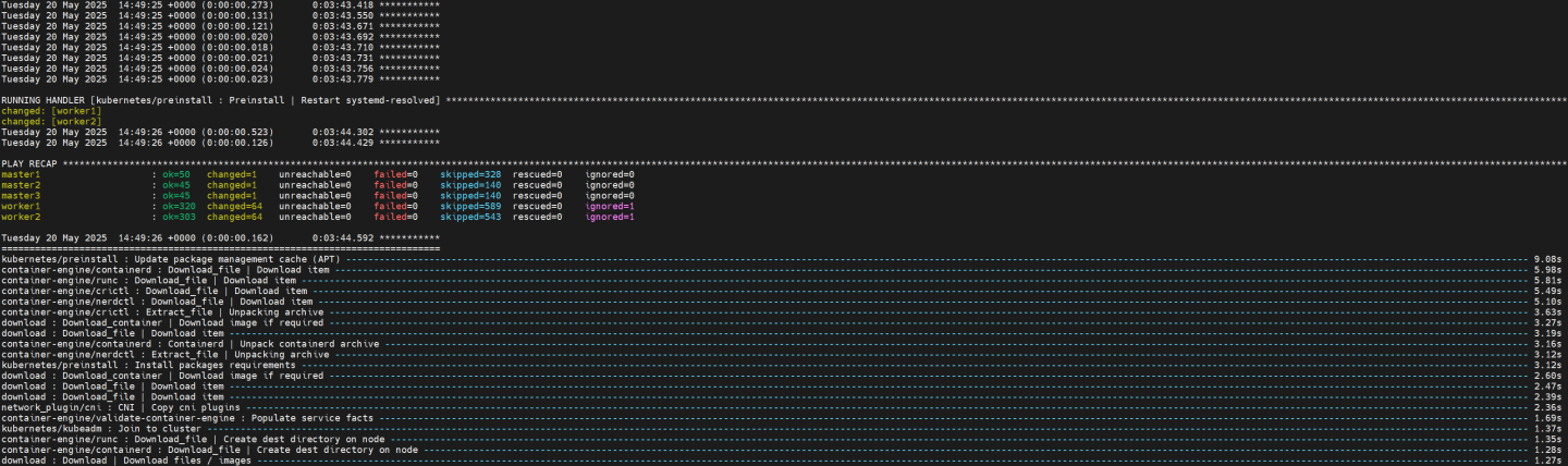
Verification
To follow the progress of the DPU provisioning, run the following command to check in which phase it currently is:
Jump Node Console
            $ watch -n10 "kubectl describe dpu -n dpf-operator-system | grep 'Node Name\|Type\|Last\|Phase'"
Every 10.0s: kubectl describe dpu -n dpf-operator-system | grep 'Node Name\|Type\|Last\|Phase'                                                                                                                                   jump: Tue May 20 14:54:41 2025

  Dpu Node Name:                                      worker1
    Last Transition Time:  2025-05-20T14:51:54Z
    Type:                  Initialized
    Last Transition Time:  2025-05-20T14:51:54Z
    Type:                  BFBReady
    Last Transition Time:  2025-05-20T14:52:09Z
    Type:                  NodeEffectReady
    Last Transition Time:  2025-05-20T14:52:10Z
    Type:                  InterfaceInitialized
    Last Transition Time:  2025-05-20T14:52:11Z
    Type:                  FWConfigured
  Phase:  OS Installing
  Dpu Node Name:                                      worker2
    Last Transition Time:  2025-05-20T14:50:34Z
    Type:                  Initialized
    Last Transition Time:  2025-05-20T14:50:34Z
    Type:                  BFBReady
    Last Transition Time:  2025-05-20T14:50:49Z
    Type:                  NodeEffectReady
    Last Transition Time:  2025-05-20T14:50:50Z
    Type:                  InterfaceInitialized
    Last Transition Time:  2025-05-20T14:50:51Z
    Type:                  FWConfigured
  Phase:  OS Installing
Validate that the DPUs have been provisioned successfully by ensuring they're in a ready state:
Jump Node Console
            $ kubectl wait --for=condition=ready --namespace dpf-operator-system dpu --all
dpu.provisioning.dpu.nvidia.com/worker1-0000-89-00 condition met
dpu.provisioning.dpu.nvidia.com/worker2-0000-89-00 condition met
Ensure that the following DaemonSets each have two ready replicas:
Jump Node Console
            $ kubectl wait ds --for=jsonpath='{.status.numberReady}'=2 --namespace nvidia-network-operator kube-multus-ds sriov-network-config-daemon sriov-device-plugin
daemonset.apps/kube-multus-ds condition met
daemonset.apps/sriov-network-config-daemon condition met
daemonset.apps/sriov-device-plugin condition met

$ kubectl wait ds --for=jsonpath='{.status.numberReady}'=2 --namespace ovn-kubernetes ovnkube-node-dpu-host
daemonset.apps/ovnkube-node-dpu-host condition met
Validate that all the different DPUServices, DPUServiceIPAMs, DPUServiceInterfaces and DPUServiceChains objects are now in a ready state
Jump Node Console
            $ kubectl wait --for=condition=ApplicationsReady --namespace dpf-operator-system dpuservices -l svc.dpu.nvidia.com/owned-by-dpudeployment=dpf-operator-system_ovn-hbn-snap
dpuservice.svc.dpu.nvidia.com/doca-snap-sk6hj condition met
dpuservice.svc.dpu.nvidia.com/hbn-gjdzr condition met
dpuservice.svc.dpu.nvidia.com/ovn-tfc8q condition met
dpuservice.svc.dpu.nvidia.com/snap-configuration-48rqj condition met
dpuservice.svc.dpu.nvidia.com/snap-controller-vgvfl condition met
dpuservice.svc.dpu.nvidia.com/snap-csi-plugin-b76c4 condition met
dpuservice.svc.dpu.nvidia.com/snap-node-driver-ktx2c condition met
dpuservice.svc.dpu.nvidia.com/spdk-csi-controller-gmqcd condition met
dpuservice.svc.dpu.nvidia.com/spdk-csi-dpu-controller-v5sl5 condition met
dpuservice.svc.dpu.nvidia.com/storage-vendor-dpu-plugin-8cksj condition met


$ kubectl wait --for=condition=DPUIPAMObjectReady --namespace dpf-operator-system dpuserviceipam --all
dpuserviceipam.svc.dpu.nvidia.com/loopback condition met
dpuserviceipam.svc.dpu.nvidia.com/pool1 condition met
dpuserviceipam.svc.dpu.nvidia.com/spdk-pool condition met

$ kubectl wait --for=condition=ServiceInterfaceSetReady --namespace dpf-operator-system dpuserviceinterface --all
dpuserviceinterface.svc.dpu.nvidia.com/doca-snap-app-sf-v8cfj condition met
dpuserviceinterface.svc.dpu.nvidia.com/hbn-p0-if-dg47c condition met
dpuserviceinterface.svc.dpu.nvidia.com/hbn-p1-if-t27cz condition met
dpuserviceinterface.svc.dpu.nvidia.com/hbn-pf2dpu2-if-w7w7l condition met
dpuserviceinterface.svc.dpu.nvidia.com/hbn-snap-if-6trz9 condition met
dpuserviceinterface.svc.dpu.nvidia.com/ovn condition met
dpuserviceinterface.svc.dpu.nvidia.com/p0 condition met
dpuserviceinterface.svc.dpu.nvidia.com/p1 condition met


$ kubectl wait --for=condition=ServiceChainSetReady --namespace dpf-operator-system dpuservicechain --all
dpuservicechain.svc.dpu.nvidia.com/ovn-hbn-snap-gj8f5 condition met
Congratulations, the DPF system has been successfully installed!
Deployment Validation
The current implementation of DOCA SNAP for DPF supports only RAW Block device volumes.
To verify the DPF deployment with DOCA SNAP storage services by using following simple workload:
Deploy a simple workload pod with PVC storage provisioning:
manifests/06-test-traffic/snap-workloads.yaml
--- apiVersion: v1 kind: Pod metadata: name: snap-storage-pod spec: containers: - name: myfrontend image: ubuntu:
24.04command: - sh - -c - sleep inf volumeDevices: - name: data devicePath: /dev/xvda volumes: - name: data persistentVolumeClaim: claimName: myclaim --- apiVersion: v1 kind: PersistentVolumeClaim metadata: name: myclaim spec: storageClassName: snap accessModes: - ReadWriteOnce volumeMode: Block resources: requests: storage: 8Gi --- apiVersion: storage.k8s.io/v1 kind: StorageClass metadata: name: snap annotations: storageclass.kubernetes.io/is-default-class:"true"provisioner: csi.snap.nvidia.com parameters: policy:"policy1"Validate deployment with simple performance tests:
            $ kubectl exec -it snap-storage-pod -- bash
root@snap-storage-pod:/# ls -la /dev/xvda
brw-rw---- 1 root disk 259, 8 May 27 09:31 /dev/xvda

root@snap-storage-pod:/# dd if=/dev/zero of=/dev/xvda bs=4k count=2000k
2048000+0 records in
2048000+0 records out
8388608000 bytes (8.4 GB, 7.8 GiB) copied, 2.42949 s, 3.5 GB/s
Create two job configuration files for FIO tests (FIO Ubuntu package should be installed: apt-get install -y fio):
            root@snap-storage-pod:~# cat job-1M.fio
[global]
ioengine=libaio
iodepth=32
direct=1
rw=read
bs=1M
numjobs=8
runtime=60
time_based
group_reporting

[job1]
filename=/dev/xvda

root@snap-storage-pod:~# cat job-4k.fio
[global]
ioengine=libaio
direct=1
iodepth=32
rw=read
bs=64k
numjobs=8
runtime=60
time_based
group_reporting

[job1]
filename=/dev/xvda
Run performance tests:
            root@snap-storage-pod:~# fio job-1M.fio
job1: (g=0): rw=read, bs=(R) 1024KiB-1024KiB, (W) 1024KiB-1024KiB, (T) 1024KiB-1024KiB, ioengine=libaio, iodepth=32
...
fio-3.36
Starting 8 processes
Jobs: 8 (f=8): [R(8)][100.0%][r=3311MiB/s][r=3311 IOPS][eta 00m:00s]
job1: (groupid=0, jobs=8): err= 0: pid=3798: Tue May 27 09:33:41 2025
  read: IOPS=3236, BW=3237MiB/s (3394MB/s)(190GiB/60007msec)
    slat (usec): min=34, max=58507, avg=2469.73, stdev=7557.90
    clat (msec): min=5, max=161, avg=76.55, stdev=20.68
     lat (msec): min=5, max=163, avg=79.01, stdev=19.97
    clat percentiles (msec):
     |  1.00th=[   36],  5.00th=[   39], 10.00th=[   40], 20.00th=[   43],
     | 30.00th=[   84], 40.00th=[   86], 50.00th=[   87], 60.00th=[   88],
     | 70.00th=[   89], 80.00th=[   90], 90.00th=[   92], 95.00th=[   93],
     | 99.00th=[   96], 99.50th=[   99], 99.90th=[  107], 99.95th=[  114],
     | 99.99th=[  159]
   bw (  MiB/s): min= 2528, max= 3580, per=99.91%, avg=3233.68, stdev=16.98, samples=952
   iops        : min= 2524, max= 3580, avg=3233.56, stdev=17.00, samples=952
  lat (msec)   : 10=0.02%, 20=0.03%, 50=23.48%, 100=76.18%, 250=0.29%
  cpu          : usr=0.08%, sys=3.95%, ctx=1483542, majf=0, minf=203142
  IO depths    : 1=0.1%, 2=0.1%, 4=0.1%, 8=0.1%, 16=0.1%, 32=99.9%, >=64=0.0%
     submit    : 0=0.0%, 4=100.0%, 8=0.0%, 16=0.0%, 32=0.0%, 64=0.0%, >=64=0.0%
     complete  : 0=0.0%, 4=100.0%, 8=0.0%, 16=0.0%, 32=0.1%, 64=0.0%, >=64=0.0%
     issued rwts: total=194218,0,0,0 short=0,0,0,0 dropped=0,0,0,0
     latency   : target=0, window=0, percentile=100.00%, depth=32

Run status group 0 (all jobs):
   READ: bw=3237MiB/s (3394MB/s), 3237MiB/s-3237MiB/s (3394MB/s-3394MB/s), io=190GiB (204GB), run=60007-60007msec

Disk stats (read/write):
  nvme1n3: ios=1548902/0, sectors=396518912/0, merge=0/0, ticks=15298488/0, in_queue=15298488, util=99.90%

===================================================================================================================
root@snap-storage-pod:~# fio job-4k.fio
job1: (g=0): rw=read, bs=(R) 64.0KiB-64.0KiB, (W) 64.0KiB-64.0KiB, (T) 64.0KiB-64.0KiB, ioengine=libaio, iodepth=32
...
fio-3.36
Starting 8 processes
Jobs: 8 (f=8): [R(8)][100.0%][r=3193MiB/s][r=51.1k IOPS][eta 00m:00s]
job1: (groupid=0, jobs=8): err= 0: pid=3856: Tue May 27 09:35:22 2025
  read: IOPS=50.8k, BW=3175MiB/s (3329MB/s)(186GiB/60020msec)
    slat (usec): min=3, max=564, avg=10.33, stdev= 6.31
    clat (usec): min=1226, max=61859, avg=5028.10, stdev=10597.80
     lat (usec): min=1243, max=61869, avg=5038.44, stdev=10597.61
    clat percentiles (usec):
     |  1.00th=[ 1680],  5.00th=[ 1811], 10.00th=[ 1926], 20.00th=[ 2114],
     | 30.00th=[ 2278], 40.00th=[ 2409], 50.00th=[ 2540], 60.00th=[ 2671],
     | 70.00th=[ 2868], 80.00th=[ 3097], 90.00th=[ 3654], 95.00th=[45876],
     | 99.00th=[51643], 99.50th=[54264], 99.90th=[56361], 99.95th=[57934],
     | 99.99th=[58983]
   bw (  MiB/s): min= 2895, max= 3316, per=100.00%, avg=3177.29, stdev= 8.07, samples=952
   iops        : min=46332, max=53068, avg=50836.59, stdev=129.11, samples=952
  lat (msec)   : 2=14.08%, 4=78.17%, 10=2.71%, 20=0.01%, 50=1.51%
  lat (msec)   : 100=3.53%
  cpu          : usr=1.06%, sys=8.50%, ctx=2446739, majf=0, minf=4446
  IO depths    : 1=0.1%, 2=0.1%, 4=0.1%, 8=0.1%, 16=0.1%, 32=100.0%, >=64=0.0%
     submit    : 0=0.0%, 4=100.0%, 8=0.0%, 16=0.0%, 32=0.0%, 64=0.0%, >=64=0.0%
     complete  : 0=0.0%, 4=100.0%, 8=0.0%, 16=0.0%, 32=0.1%, 64=0.0%, >=64=0.0%
     issued rwts: total=3049161,0,0,0 short=0,0,0,0 dropped=0,0,0,0
     latency   : target=0, window=0, percentile=100.00%, depth=32

Run status group 0 (all jobs):
   READ: bw=3175MiB/s (3329MB/s), 3175MiB/s-3175MiB/s (3329MB/s-3329MB/s), io=186GiB (200GB), run=60020-60020msec

Disk stats (read/write):
  nvme1n3: ios=3043368/0, sectors=389554432/0, merge=26/0, ticks=15279103/0, in_queue=15279103, util=99.86%
At the end of the test, you'll see the achieved performance.
NoteThe performance results listed in this guide are indicative and should not be considered as formal performance targets for NVIDIA products.
Authors

| Vitaliy Razinkov Vitaliy Razinkov is a Solutions Architect on the NVIDIA Networking team, specializing in complex Kubernetes, OpenShift, and Microsoft solutions. With over 25 years of experience in senior technical roles, he brings deep expertise in designing and implementing advanced infrastructures. Vitaliy has authored several reference design guides on Microsoft technologies, RoCE/RDMA-accelerated machine learning in Kubernetes/OpenShift, and containerized solutions—all available on the NVIDIA Networking Documentation site. |
This document is provided for information purposes only and shall not be regarded as a warranty of a certain functionality, condition, or quality of a product. NVIDIA Corporation (“NVIDIA”) makes no representations or warranties, expressed or implied, as to the accuracy or completeness of the information contained in this document and assumes no responsibility for any errors contained herein. NVIDIA shall have no liability for the consequences or use of such information or for any infringement of patents or other rights of third parties that may result from its use. This document is not a commitment to develop, release, or deliver any Material (defined below), code, or functionality. NVIDIA reserves the right to make corrections, modifications, enhancements, improvements, and any other changes to this document, at any time without notice. Customer should obtain the latest relevant information before placing orders and should verify that such information is current and complete. NVIDIA products are sold subject to the NVIDIA standard terms and conditions of sale supplied at the time of order acknowledgement, unless otherwise agreed in an individual sales agreement signed by authorized representatives of NVIDIA and customer (“Terms of Sale”). NVIDIA hereby expressly objects to applying any customer general terms and conditions with regards to the purchase of the NVIDIA product referenced in this document. No contractual obligations are formed either directly or indirectly by this document.