SN2100/SN2010 Side by Side Mounting Rail Kit
The installation process is demonstrated on an SN2100 system, but applies to the SN2010 series as well.
A designated rail kit for the SN2100/SN2010 systems can be purchased separately.
This section is relevant to short-depth systems that allow such a form of installation only.
Kit Part Number | Kit Legacy Part Number | Rack Size and Rack Depth Range |
930-9NRKT-00JG-000 | MTEF-KIT-D | Rack installation kit for SN2100/SN2010 series short depth 1U switches, allows installation of one or two switches side-by-side into standard depth racks. |
All servers and systems in the rack should be planned with the airflow direction. All FRU components must have the same air flow direction. A mismatch in the air flow will affect the heat dissipation.
1 x System
2 x Power cables – Type C13-C14
1 x Harness RS232 2M cable – DB9 to RJ-45
The following items are not included in the SN2010 package, and can be purchased separately:
Rack installation kit for SN2010 series short depth 1U switches, allows installation of one switch into standard depth racks (23.6"-31.5"/600-800mm)
1 metal frame for two systems (A)
2 system mounting blades with 8 screw holes - the kit contains enough rails to install 2 systems (B)
2 system mounting blades with 7 screw holes - the kit contains enough rails to install 2 systems (C)
2 blank (installed) covers (D)
30 flat head 4-40 screws - the kit contains enough screws to install 2 systems (E)
2 frame rail slides (F)
10 (+2 spare units) M6 pan head screws (G)
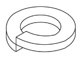
10 (+2 spare units) M6 spring washers (H)
10 (+2 spare units) M6 spring steel cage nuts (I)
6 (+2 spare units) cable-ties (J)
Quantity | Item |
X30 - For Side-by-Side Installation X15 - For a single switch | E
|
X10 (of each) | I, G, H
|
X2 (of each) | C B+F
|
1X | A+D
|
X1 | 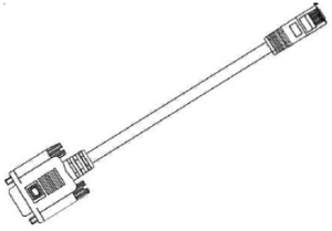
|
X2 | 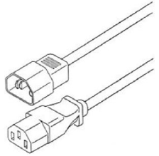
|
X8 | J
|
If anything is damaged or missing, contact your NVIDIA representative at Networking-support@nvidia.com.
Prerequisites
Before mounting the system to the rack, select the way you wish to place the system. Pay attention to the airflow within the rack cooling, connector and cabling options.
The installation kits come with enough system mounted rails and flat head screws to install two systems.
The 2 system metal frame will fit into racks with from 23.6” (600mm) to 31.5” (800mm) space between the vertical supports.
You may choose to install your system in the right or in the left part of the metal frame. The following instructions apply to installation in the right part. For installation in the frame’s left part, follow the same instructions, while replacing “right” with “left”, and vice versa.
At least two people are required to safely mount the system in the rack.
# | Illustration |
1 | Insert the SE (single ended) plugs to the dedicated inlets in the system’s rear panel. Carefully position the SE cables one on top of the other, and use 3 cable-ties to pair them together. Note
While pairing the cables, make sure the cables are paired in symmetry to the switch, in order to avoid damaging the cables.

Place the coupled cables in the designated area within the right flat blade (the blade with 7 screw holes). 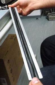
|
2 |
Warning
In the this step you will be attaching the mounting rails to the switch sides. Before doing that, make sure the cables are laid properly within them. Avoid using excessive pressure, as it can damage the cables. While holding the cables stably together in the blade’s rail with one hand, use your other hand to secure the blades to the chassis. Screw the right blade with eight 4-40 flathead screws, and the left blade with seven 4-40 flathead screws. The recommended torque is 0.49-0.54 Nm. 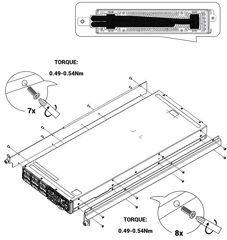
Attached Rail with Threaded Cables - Top View: 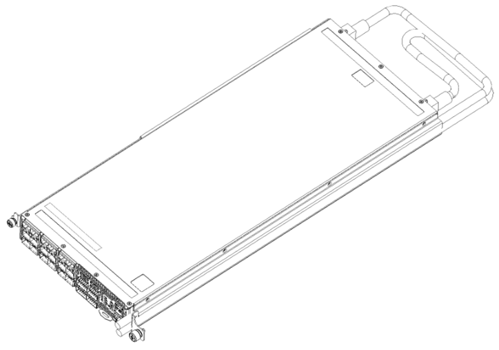
|
3 | Slide the two frame slides into the dedicated rails in the metal frame. 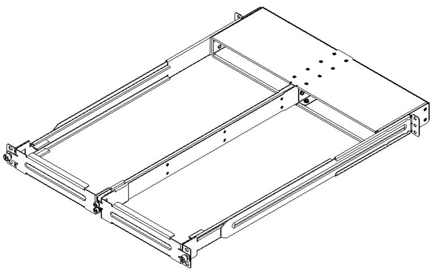
|
4 | Attach the frame to the rack by using ten spacer cage nuts, and screw ten M6 pan head screws - four in the front part of the rack, and 6 in its rear part. The recommended torque is 6.55-7.35 Nm. 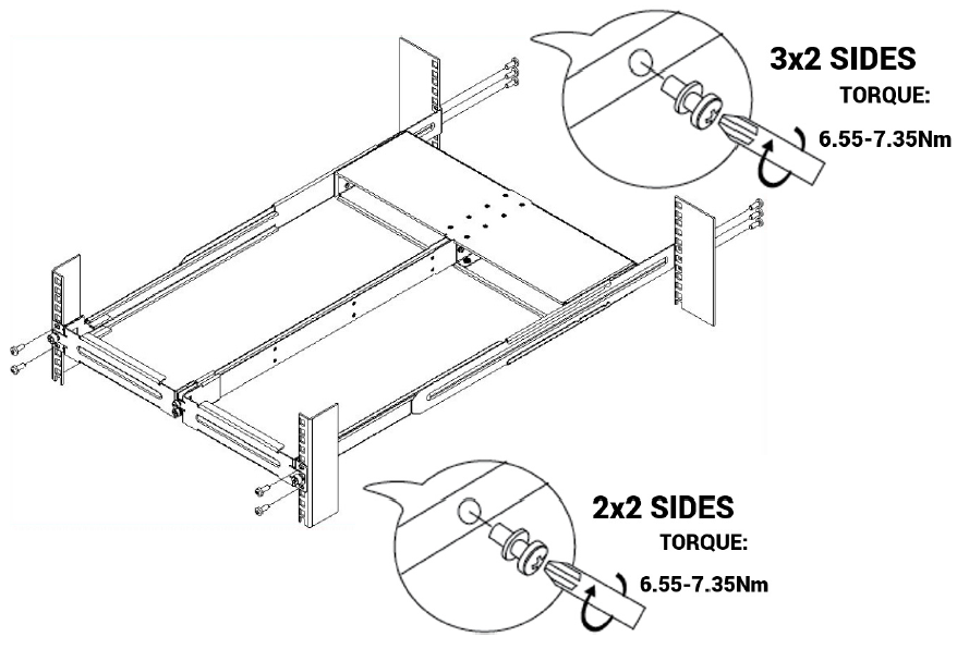
|
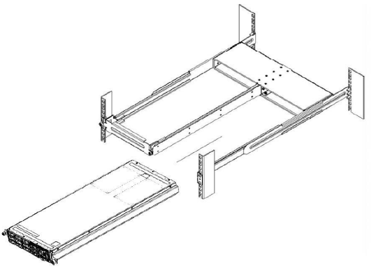
5 | Remove the blank cover from the selected slot in the frame, and mount the system by sliding its mounting blades into the frame. Repeat this step to install an additional system in the other side of the frame, if needed. Warning
Do not remove both of the blank covers at the same time. When no system is installed, at least one of them should be present to support the frame’s partition.
|
5 | Tighten the capture nuts to secure the system in the frame. The recommended torque on the right screw is 3.0-3.36 Nm while on the left screw recommended torque is 0.89-0.98 Nm. 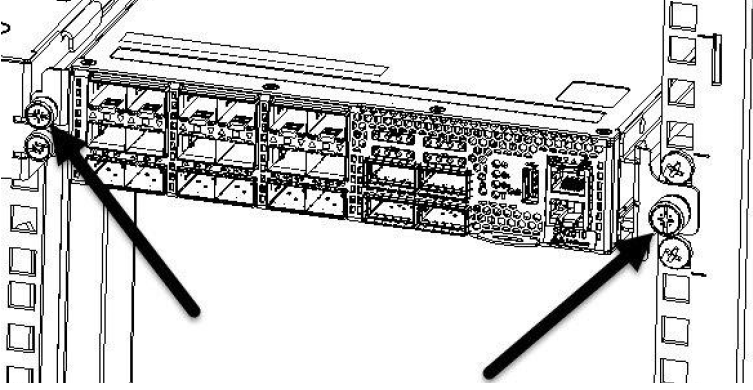
|
6 |
Note
A cable retainer should be used to secure the power cord when plugging it into each power socket (located on the rear side of the switch). To secure the power cord inside the retainer, press the small tab on the retainer strip to loosen the loop and pull. (The following diagram is for general illustration; the rear view does not necessarily match that of the actual system). 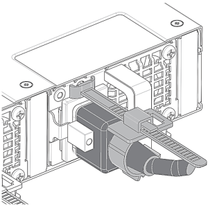
|


