Part 2. Configure the Network Hardware#
The network hardware is configured in the following steps.
Set up the GrandMaster
Set up the switch
Set up the O-RU
Part 2.1 - Setup the VIAVI Solutions GrandMaster#
The Qg 2 (picture below) is a small form factor, highly accurate Multi-Sync Gateway that provides IEEE 1588-2008 PTP Grand Master and Boundary Clock functionality. IEEE 1588-2008 PTP is also known as PTP Version 2. It is used for synchronizing the Aerial Testbed system.
Follow the steps in the VIAVI User Guide to configure the Qg 2.
Front Panel
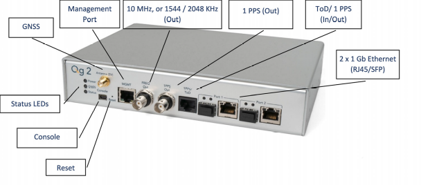
Back Panel
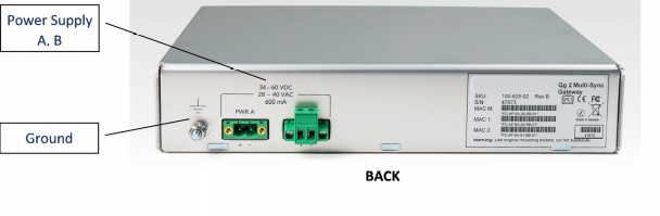
Figure credit: VIAVI QG2 Multi-Sync Gateway Users Guide#
Part 2.2 - Set up the Switch#
Dell PowerSwitch S5248F-ON#
The following example uses these VLAN 2 settings:
RUs are on ports 1 and 7
GrandMaster is on port 5
CN is on ports 11 and 12
gNB ports are connected to ports 49 and 51
Set up MGMT access to the switch (in this case 172.168.20.67):
OS10# configure terminal
OS10(config)#
interface mgmt1/1/1
no shutdown
no ip address dhcp
ip address 172.16.204.67/22
exit
Use SSH to access
admin@172.168.204.67.Set the speed to 10G for port groups 1 and 2.
OS10(config)#
port-group 1/1/1
mode Eth 10g-4x
exit
port-group 1/1/2
mode Eth 10g-4x
exit
Enable PTP on the switch.
OS10# configure terminal
OS10(config)#
ptp clock boundary profile g8275.1
ptp domain 24
ptp system-time enable
!
Configure the GrandMaster port.
OS10(config)#
interface ethernet 1/1/5:1
no shutdown
no switchport
ip address 169.254.2.1/24
flowcontrol receive off
ptp delay-req-min-interval -4
ptp enable
ptp sync-interval -4
ptp transport layer2
exit
After some time, the following values will print:
<165>1 2023-05-09T07:49:22.625584+00:00 OS10 dn_alm 1021 - - Node.1-Unit.1:PRI [event], Dell EMC (OS10) %PTP_SYSTEM_TIME_NOT_SET: System time is not set. System time will be set when the clock is.
<165>1 2023-05-09T07:51:22.312557+00:00 OS10 dn_alm 1021 - - Node.1-Unit.1:PRI [event], Dell EMC (OS10) %PTP_CLOCK_PHASE_LOCKED: Clock servo is phase locked.
<165>1 2023-05-09T07:51:22.313081+00:00 OS10 dn_alm 1021 - - Node.1-Unit.1:PRI [event], Dell EMC (OS10) %PTP_SYSTEM_TIME_UPDATE_STARTED: System time update service is started. Update interval: 60 minutes.
<165>1 2023-05-09T07:51:59.334346+00:00 OS10 dn_alm 1021 - - Node.1-Unit.1:PRI [event], Dell EMC (OS10) %ALM_CLOCK_UPDATE: Clock changed MESSAGE=apt-daily.timer: Adding 6h 36min 18.719270s random time.
<165>1 2023-05-09T07:57:27.254181+00:00 OS10 dn_alm 1021 - - Node.1-Unit.1:PRI [event], Dell EMC (OS10) %ALM_CLOCK_UPDATE: Clock changed MESSAGE=apt-daily.timer: Adding 4h 31mi
Configure the Fronthaul Network Configuration by creating a VLAN.
Note
If you choose to use a different VLAN, you must modify the Aerial YAML file and O-RU configuration. C- and U-planes use the same VLAN.
Create “VLAN 2”.
OS10(config)#
interface vlan 2
OS10(conf-if-vl-2)#
<165>1 2023-03-16T16:51:36.458730+00:00 OS10 dn_alm 813 - - Node.1-Unit.1:PRI [event], Dell EMC (OS10) %IFM_ASTATE_UP: Interface admin state up :vlan2

OS10(conf-if-vl-2)# show configuration
!
interface vlan2
no shutdown
OS10(conf-if-vl-2)# exit
Configure the RU, gNB, and CN ports.
Interfaces that are configured to be slower than their maximum speed have a
:1appended to their name. This applies to ports in port groups 1 and 2.no shutdown switchport mode trunk switchport trunk allowed vlan 2 mtu 8192 flowcontrol receive off ptp enable ptp transport layer2 ptp role timeTransmitter exit
Check the PTP status.
OS10# show ptp | no-more
PTP Clock : Boundary
Clock Identity : b0:4f:13:ff:ff:46:63:5f
GrandMaster Clock Identity : fc:af:6a:ff:fe:02:bc:8d
Clock Mode : One-step
Clock Quality
Class : 135
Accuracy : <=100ns
Offset Log Scaled Variance : 65535
Domain : 24
Priority1 : 128
Priority2 : 128
Profile : G8275-1(Local-Priority:-128)
Steps Removed : 1
Mean Path Delay(ns) : 637
Offset From Master(ns) : 1
Number of Ports : 8
----------------------------------------------------------------------------
Interface State Port Identity
----------------------------------------------------------------------------
Ethernet1/1/1:1 Master b0:4f:13:ff:ff:46:63:5f:1
Ethernet1/1/3:1 Master b0:4f:13:ff:ff:46:63:5f:3
Ethernet1/1/5:1 Slave b0:4f:13:ff:ff:46:63:5f:5
Ethernet1/1/7:1 Master b0:4f:13:ff:ff:46:63:5f:8
Ethernet1/1/11 Master b0:4f:13:ff:ff:46:63:5f:4
Ethernet1/1/49 Master b0:4f:13:ff:ff:46:63:5f:9
Ethernet1/1/51 Master b0:4f:13:ff:ff:46:63:5f:10
Ethernet1/1/54 Master b0:4f:13:ff:ff:46:63:5f:2
----------------------------------------------------------------------------
Number of slave ports :1
Number of master ports :7
Save the switch configuration:
copy running-configuration startup-configuration
Ciena 5164#
Use these the following documents as reference when setting up the Ciena Switch:
009-3407-008_(5170_10_6_Base_Advanced_Ethernet_and_OAM_Configuration)RevA.pdf009-3407-043_(5170_10_6_Synchronization_Configuration)RevisionA.pdf
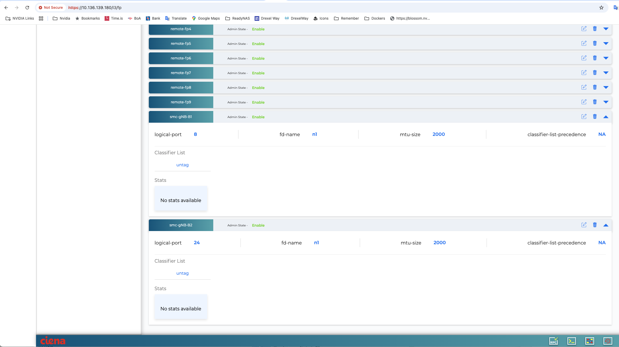
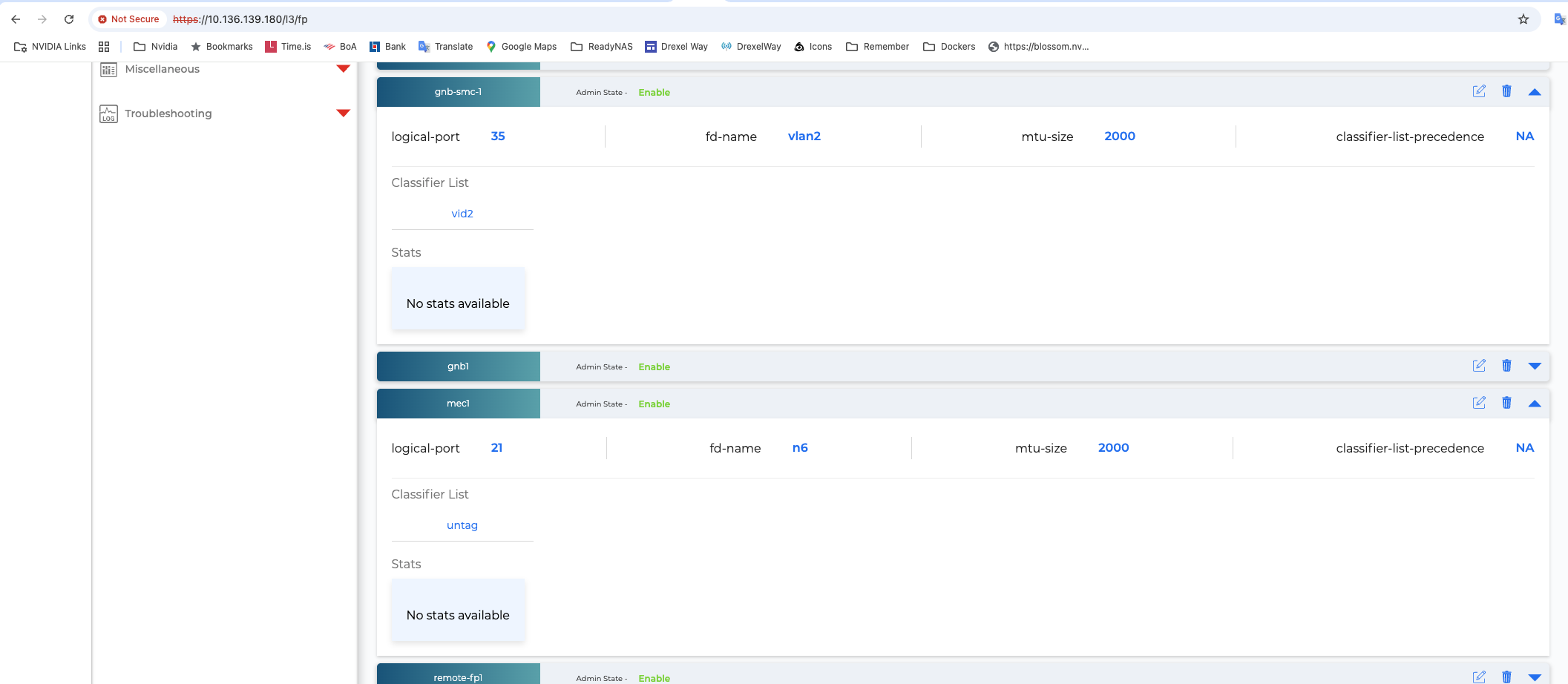
The screen shots in these documents are from a setup where the following equipment is connected to the switch:
Port 2 (vlan2) <-> Foxconn RU
Port 5 and 6 (n1) <-> CN
Port 7 (n6) <-> CN
Port 8 (n1) <-> gNB
Port 21 (n6) <-> MEC
Port 24 (n1) <-> gNB
Port 35 (vlan2) <-> gNB
Note
The switches in the screen shots have other equipment connected that is irrelevant.
The switch has been set up so that it can be accessed both from a browser and using SSH.
https://<IP_ADDRESS>/dashboard/view
Create the Flow Points#
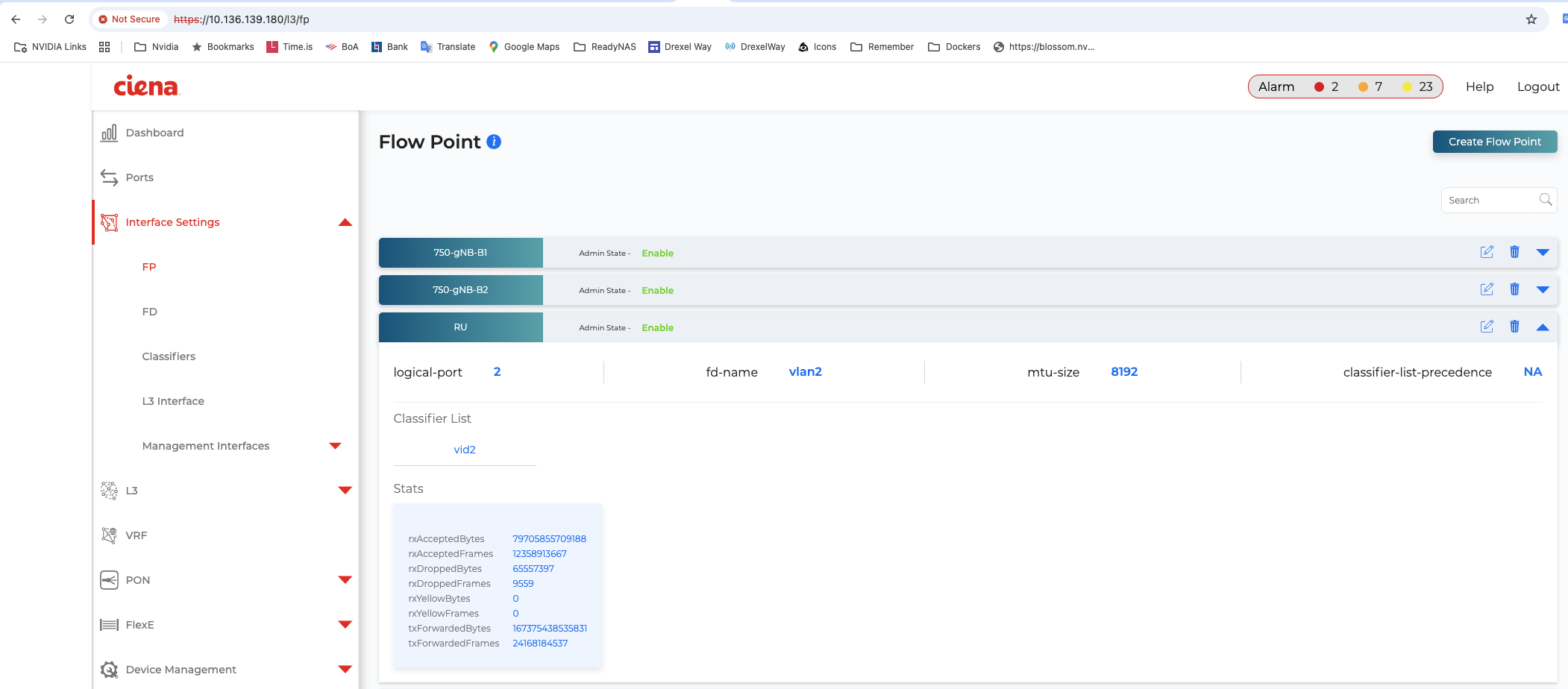
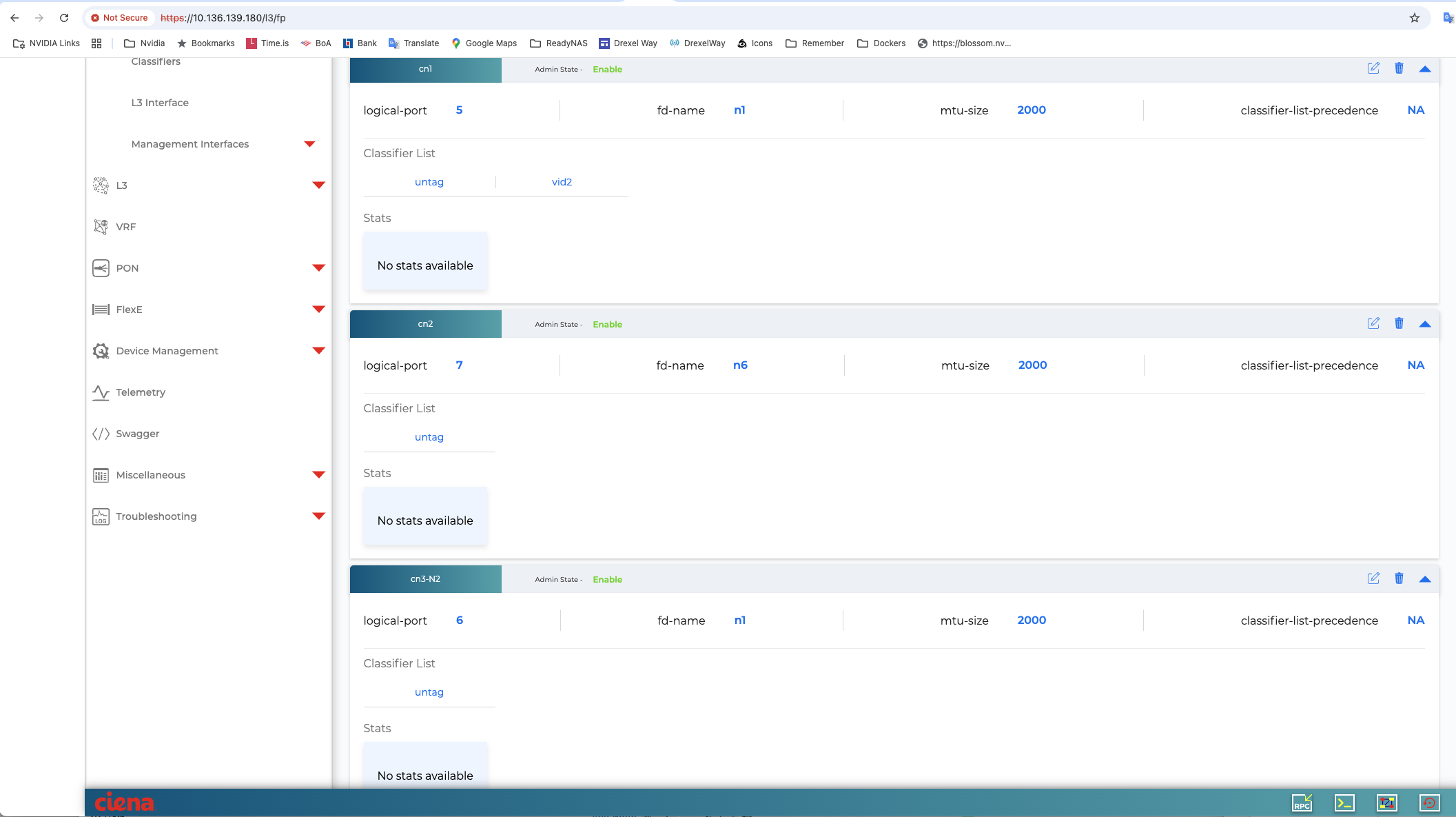
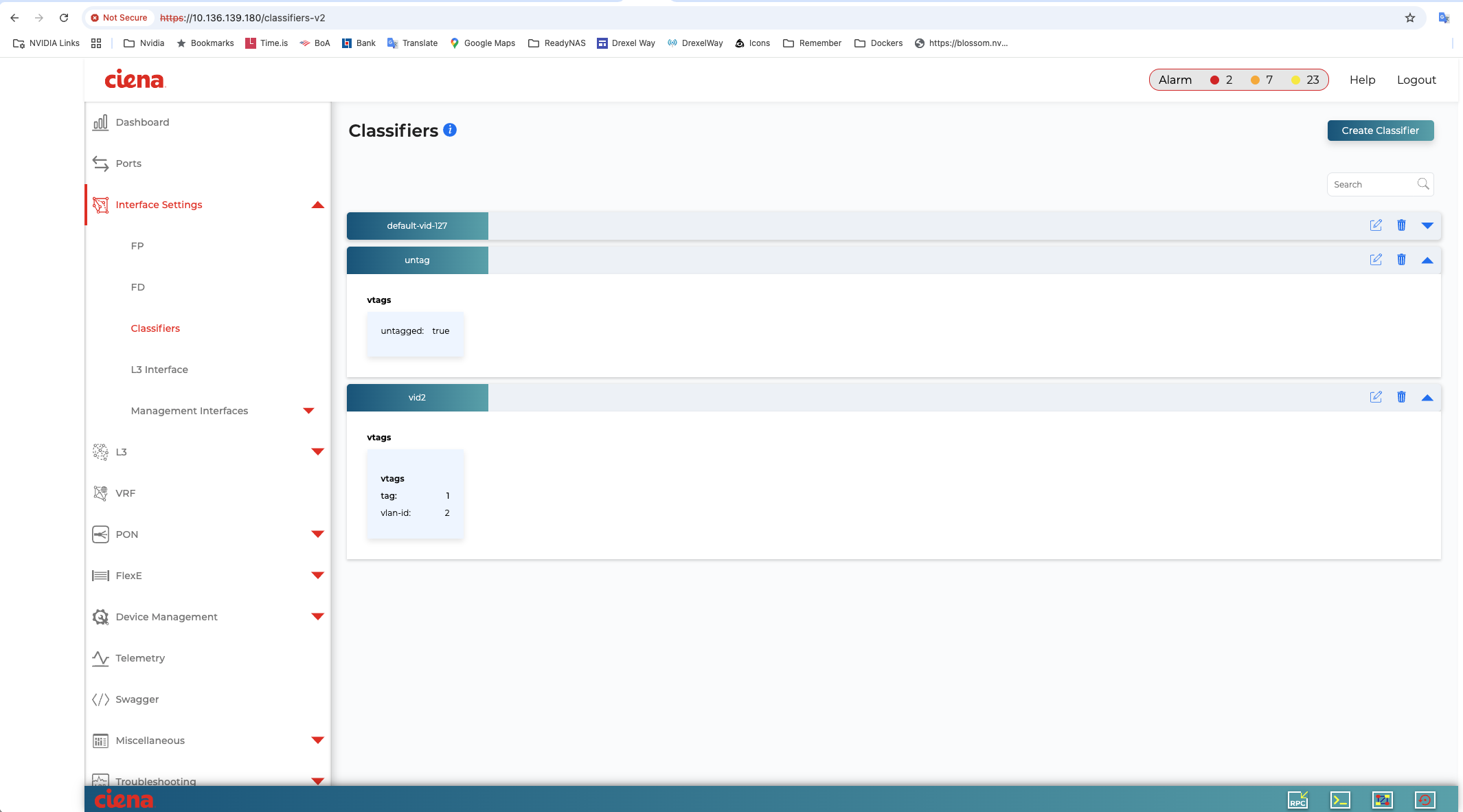
Create the Classifiers#
Create the Forwarding Domains#

Setup PTP#
Use SSH to connect to the switch (using the IP address of switch).
Enter Config mode, then add the ports to ptp:
5164-2nd> config

user@5164-2nd# sync output-references ptp-output-reference ptp_out_2 interface 2

user@5164-2nd# sync output-references ptp-output-reference ptp-out-35 interface 35

save

5164-2nd> show sync ptp

5164-2nd> show sync ptp output-references

+------------- SYNC PTP OUTPUT REFERENCES -------------+
| Name       | Interface | Oper State | PTP Port State |
+------------+-----------+------------+----------------+
| ptp_out_2  |         2 |     Up     |     Master     |
| ptp-out-35 |        35 |     Up     |     Master     |
+------------+-----------+------------+----------------+
Setup GPS#
Use SSH to connect to the switch (using the IP address of switch).
Configure the GPS:
5164-2nd> show sync gnss antenna-inputs

+---------------------------- SYNC GNSS ANTENNA INPUT -----------------------------+
| Name    | Pri | Override Pri | Forced QL | Oper State | Antenna Signal Condition |
+---------+-----+--------------+-----------+------------+--------------------------+
| GNSS_in |   - |            - |  QL-PRTC  |   Locked   |          Normal          |
+---------+-----+--------------+-----------+------------+--------------------------+

5164-2nd> show sync gnss satellites

+-- SYNC GNSS SATELLITES --+
| PRN | Acquired | SV Type |
+-----+----------+---------+
|  10 | Acquired |   GPS   |
|  23 | Acquired |   GPS   |
|  32 | Acquired |   GPS   |
|  8  | Acquired |   GPS   |
|  21 | Acquired |   GPS   |
|  2  | Acquired |   GPS   |
|  31 | Acquired |   GPS   |
|  27 | Acquired |   GPS   |
+-----+----------+---------+

5164-2nd> show sync gnss almanac

+------ SYNC GNSS ALMANAC ------+
| PRN | SV Health | Week Number |
+-----+-----------+-------------+
|  31 |     0     |     220     |
|  27 |     0     |     220     |
|  32 |     0     |     220     |
|  21 |     0     |     222     |
|  2  |     0     |     220     |
|  8  |     0     |     220     |
|  10 |     0     |     220     |
|  23 |     0     |     220     |
+-----+-----------+-------------+
FibroLAN Falcon RX#
Although the FibroLAN switch has not been qualified in the NVIDIA lab, OAI labs incorporate the following configuration and switch for interoperability.
To get started, follow the FibroLAN Falcon R Class Quick Guide Getting Started.
In this setup, the VIAVI GrandMaster is connected to port 4, the Aerial cuBB to port 17, and the O-RU to port 16 (C/U plane) and port 15 (S/M plane). You can ignore all other ports in the figures [A][B] below.
VLAN Setup#
The following assumes that the VLAN tag is 2 for both the control plane and the user plane of the O-RAN CU plane. VLAN tag 80 is used for everything else.
Open the configuration page of the FibroLAN switch, then go to Configuration > VLANs. Port 4 (the VIAVI GrandMaster) needs to be set to “Access” mode, with the port VLAN set to 80.

Figure A - VLAN Setup#
Use the same configuration for port 15 (RU S/M plane).
Configure ports 16 and 17 as follows:
Mode: “Trunk”
Port: VLAN 80
Untag Port VLAN
Allowed VLANs: 2, 80

Figure B - VLAN Setup#
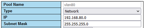
DHCP Setup#
The ORU M-plane requires you to set up a DHCP server. Go to Configuration > DHCP > Server > Pool and create a new DHCP server with the following settings:
PTP Setup on gNB#
For the PTP setup, follow the Fibrolan PTP Boundary Clock Configuration guide and use the following settings:
Device Type: “Ord-Bound”
Profile: “G8275.1”
Clock domain: 24
VLAN: 80
Also make sure you enable the used ports (in this case, 4, 15, 16, and 17).
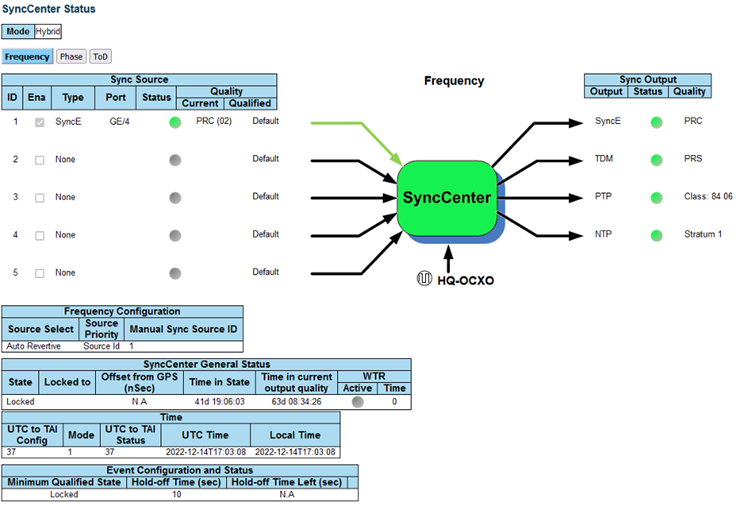
Hybrid mode is recommended as the sync mode.
If everything is configured correctly, the SyncCenter should show green.
Part 2.3 - Set up the Foxconn O-RU#
Note
Foxconn O-RUs are no longer supported. These instructions are included for previously installed O-RUs only.
O-RU M-Plane Setup#
Add the following to the bottom of
/etc/profileand comment out the line withset_qse.shif it already exists. Set the interface initially toeth0for firmware version 1, and toqse-ethafter upgrading to firmware version 2 or greater.interface=eth0 vlanid=2 ipLastOctet=20 ip link add link ${interface} name ${interface}.$vlanid type vlan id $vlanid ip addr flush dev ${interface} ip addr add 169.254.0.0/24 dev ${interface} ip addr add 169.254.1.${ipLastOctet}/24 dev ${interface}.$vlanid ip link set up ${interface}.$vlanid
Reboot the O-RU using the command
./reboot.shand check the network configuration:# ip r 169.254.1.0/24 dev eth0.2 src 169.254.1.20
Update O-RU Configuration#
Note
If you are using the CBRS O-RU, refer to the note below for the modified configuration.
Update the O-RU configuration in
/home/root/test/RRHconfig_xran.xml.root@arria10:~/test# grep -v '<!-' RRHconfig_xran.xml RRH_DST_MAC_ADDR = 08:c0:eb:71:e7:d4 # To match fronthaul interface of DU RRH_SRC_MAC_ADDR = 6C:AD:AD:00:04:6C # To match qse-eth of RU RRH_EN_EAXC_ID = 0 RRH_EAXC_ID_TYPE1 = 0x0, 0x1, 0x2, 0x3 RRH_EAXC_ID_TYPE3 = 0x8, 0x9, 0xA, 0xB RRH_EN_SPC = 1 RRH_RRH_LTE_OR_NR = 1 RRH_TRX_EN_BIT_MASK = 0x0f RRH_RF_EN_BIT_MASK = 0x0f RRH_CMPR_HDR_PRESENT = 0 RRH_CMPR_TYPE = 1, 1 RRH_CMPR_BIT_LENGTH = 9, 9 RRH_UL_INIT_SYM_ID = 0 RRH_TX_TRUNC_BITS = 4 RRH_RX_TRUNC_BITS = 4 RRH_MAX_PRB = 273 RRH_C_PLANE_VLAN_TAG = 0x0002 #To match vlan id set in cuphycontroller yaml file RRH_U_PLANE_VLAN_TAG = 0x0002 #To match vlan id set in cuphycontroller yaml file RRH_SLOT_TICKS_IN_SEC = 2000 RRH_SLOT_PERIOD_IN_SAMPLE = 61440 RRH_LO_FREQUENCY_KHZ = 3750000, 0 RRH_TX_POWER = 24, 24 RRH_TX_ATTENUATION = 12.0, 12.0, 12.0, 12.0 RRH_RX_ATTENUATION = 0.0, 0.0, 0.0, 0.0 RRH_BB_GENERAL_CTRL = 0x0, 0x0, 0x0, 0x0 RRH_RF_GENERAL_CTRL = 0x3, 0x1, 0x0, 0x0 RRH_PTPV2_GRAND_MASTER_MODE = 3 RRH_PTPV2_JITTER_LEVEL = 0 RRH_PTPV2_VLAN_ID = 0 RRH_PTPV2_IP_MODE = 4 RRH_PTPV2_GRAND_MASTER_IP = 192.167.27.150 RRH_PTPV2_SUB_DOMAIN_NUM = 24 RRH_PTPV2_ACCEPTED_CLOCK_CLASS = 135 RRH_TRACE_PERIOD = 10 RRH_DL_IQ_SCALING = 0x1001 RRH_CFR_PEAK_THRESHOLD = 0.5
Note
The above configuration was taken from an ORU running firmware 3.1.15.
Note
If you’re using the CBRS O-RU, the above parameters should be modified as follows:
RRH_LO_FREQUENCY_KHZ = 3649140, 0Reboot O-RU.
cd /home/root/test/

./reboot
Run the following to enable the configuration:
cd /home/root/test/

./init_rrh_config_enable_cuplane
To see the ORU status, run the following script.
cd /home/root/test/

./chk_con.sh
Part 2.4 - Set up the WNC O-RU#
When the the O-RU starts up, it will have a baseline configuration. Access the O-RU using the following command: ssh root@192.168.2.1 (no password is required). The radio interfaces will be “shutdown”.
ru# show running-config
...
interface eth1
  no shutdown
  mac-address e8:c7:cf:ac:58:32
  l2-mtu 9600
  ip address 192.168.2.1/24
  sfp rs0-high
  no sfp rs1-high
  ip dhcp client vendor-class-identifier o-ran-ru2/WNC/R1220-077L
  sub-interface eth1.mplane encapsulation vlan 100
  sub-interface eth1.ecpri encapsulation vlan 564
  exit
!
...
radio 1
  shutdown
  center-freq 3750000
  transmit-power 24
  lna shutdown
Then SSH again as shown above. Start the radio as shown below. Look for the “no shutdown” message.
============================
WNC O-RU Command Line System
============================
ru# radio enable
ru# show running-config
!
hostname ru
!
...
radio 1
  no shutdown
  center-freq 3750000
  transmit-power 24
  no lna shutdown
Check PTP:
ru# show ptp clock
PTP Clock Information:
  PTP Device Type                  : slave clock
  Clock Identify                   : e8c7cf.fffe.ac5832
  Profile                          : g.8275.1
  Clock Domain                     : 24
  Number of PTP ports              : 1
  Priority1                        : 128
  Priority2                        : 128
  Clock Quality                    :
      Class                        : 255
      Accuracy                     : 0xfe
      Offset (log variance)        : 0xffff
  Offset From Master(ns)           : -4.0
  Mean Path Delay(ns)              : 206.0
  Steps Removed                    : 2
  S-plane State                    : locked
OK
PCP is fixed at 7 with the WNC radio and cannot be changed. This must be changed in the cuphycontroller.yaml file.
Changing VLAN can be done as follows:
Tell the radio to use a different interface for eCPRI transport
Delete the ecpri interface with old vlan
Create the eCPRI interface with new vlan
Change the radio to use that eth1.ecpri interface again
Or see section 2.2.7 of the WNC manual.
ru# config
OK
ru(config)# radio 1
OK
ru(conf-rf 1)# transport interface eth1.mplane
OK
ru(conf-rf 1)# exit
OK
ru(config)# interface eth1
OK
ru(conf-if eth1)# no sub-interface eth1.ecpri
OK
ru(conf-if eth1)# sub-interface eth1.ecpri encapsulation vlan 2
OK
ru(conf-if eth1)# Listening on interface eth1.ecpri for CFM frames

ru(conf-if eth1)# exit
OK
ru(config)# radio 1
OK
ru(conf-rf 1)# transport interface eth1.ecpri
OK
Reference Configuration#
For refence, Aerial Testbed has been verified with the following radio configuration.
radio 1
  no shutdown
  center-freq 3750000
  transmit-power 24
  no lna shutdown
  lna low-gain
  eaxc-id downlink 0x0000
  eaxc-id uplink 0x0000
  eaxc-id prach 0x0004
  transport interface eth1.ecpri
  transport peer-mac 9c:63:c0:f4:26:d2
  phase-compensation
  bandwidth 100
  sub-carrier 30
  max-scs 30
  transmit-power-scale 0.0
  compress tx static bfp iq-bitwidth 9
  compress rx static bfp iq-bitwidth 9
  compress prach static bfp iq-bitwidth 9
  compress oran-compliant
  downlink-radio-frame-offset 0
  downlink-sfn-offset 0
  ul-gain-correction 0.0000
  digital-power-scaling o-ran
  fs-offset tx 0
  fs-offset rx 0
  fs-offset prach 0
  exit
!