Concepts#
Terminology#
This section introduces some terminology used to describe the concepts behind MIG.
Streaming Multiprocessor
A streaming multiprocessor (SM) executes compute instructions on the GPU.
GPU Context
A GPU context is analogous to a CPU process. It encapsulates all the resources necessary to execute operations on the GPU, including a distinct address space, memory allocations, etc. A GPU context has the following properties:
Fault isolation
Individually scheduled
Distinct address space
GPU Engine
A GPU engine is what executes work on the GPU. The most commonly used engine is the Compute/Graphics engine that executes the compute instructions. Other engines include the copy engine (CE) that is responsible for performing DMAs, NVDEC for video decoding, NVENC for encoding, etc. Each engine can be scheduled independently and execute work for different GPU contexts.
GPU Memory Slice
A GPU memory slice is the smallest fraction of the GPU’s memory, including the corresponding memory controllers and cache. A GPU memory slice is roughly one eighth of the total GPU memory resources, including both capacity and bandwidth.
GPU SM Slice
A GPU SM slice is the smallest fraction of the SMs on the GPU. A GPU SM slice is roughly one seventh of the total number of SMs available in the GPU when configured in MIG mode.
GPU Slice
A GPU slice is the smallest fraction of the GPU that combines a single GPU memory slice and a single GPU SM slice.
GPU Instance
A GPU Instance (GI) is a combination of GPU slices and GPU engines (DMAs, NVDECs, and so on). Anything within a GPU instance always shares all the GPU memory slices and other GPU engines, but it’s SM slices can be further subdivided into compute instances (CI). A GPU instance provides memory QoS. Each GPU slice includes dedicated GPU memory resources which limit both the available capacity and bandwidth, and provide memory QoS. Each GPU memory slice gets 1/8 of the total GPU memory resources and each GPU SM slice gets 1/7 of the total number of SMs.
Compute Instance
A GPU instance can be subdivided into multiple compute instances. A Compute Instance (CI) contains a subset of the parent GPU instance’s SM slices and other GPU engines (DMAs, NVDECs, etc.). The CIs share memory and engines.
Partitioning#
Using the concepts introduced above, this section provides an overview of how the user can create various partitions on the GPU. For illustration purposes, the document will use the A100-40GB as an example, but the process is similar for other GPUs that support MIG.
GPU Instance
Partitioning of the GPU happens using memory slices, so the A100-40GB GPU can be thought of having 8x5GB memory slices and 7 SM slices as shown in the diagram below.
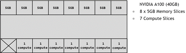
Figure 2 Available Slices on A100#
As explained above, then to create a GPU Instance (GI) requires combining some number of memory slices with some number of
compute slices. In the diagram below, a 5GB memory slice is combined with 1 compute slice to create a 1g.5gb GI profile:
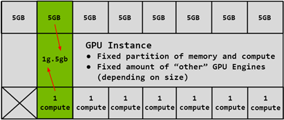
Figure 3 Combining 5GB Memory and One Compute Slice#
Similarly, 4x5GB memory slices can be combined with 4x1 compute slices to create the 4g.5gb GI profile:
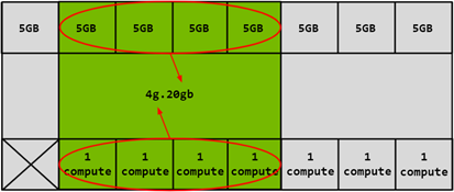
Figure 4 Combining 4x5GB Memory and 4x1 Compute Slices#
Compute Instance
The compute slices of a GPU Instance can be further subdivided into multiple Compute Instances (CI), with the CIs sharing the engines and memory of the parent GI, but each CI has dedicated SM resources.
Using the same 4g.20gb example above, a CI may be created to consume only the first compute slice as shown below:
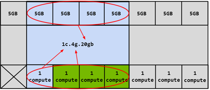
Figure 5 Combining Memory and First Compute Slice#
In this case, four different CIs can be created by choosing any of the compute slices. Two compute slices can also
be combined together to create a 2c.4g.20gb profile:
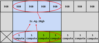
Figure 6 Combining Memory and Two Compute Slices#
In this example, 3 compute slices can also be combined to create a 3c.4g.20gb profile or all 4 can be combined to
create a 4c.4g.20gb profile. When all 4 compute slices are combined, the profile is simply referred to as the 4g.20gb profile.
Refer to the sections on the canonical naming scheme and the CUDA device terminology.
Profile Placement
The number of slices that a GI can be created with is not arbitrary. The NVIDIA driver APIs provide a number of “GPU Instance Profiles” and users can create GIs by specifying one of these profiles.
On a given GPU, multiple GIs can be created from a mix and match of these profiles, so long as enough slices are available to satisfy the request.
Note
The table below shows the profile names on the A100-SXM4-40GB product. For A100-SXM4-80GB, the profile names will
change according to the memory proportion - for example, 1g.10gb, 2g.20gb, 3g.40gb, 4g.40gb, 7g.80gb respectively.
For a list of all supported combinations of profiles on MIG-enabled GPUs, refer to the section on supported profiles.
Profile Name |
Fraction of Memory |
Fraction of SMs |
Hardware Units |
L2 Cache Size |
Copy Engines |
Number of Instances Available |
|---|---|---|---|---|---|---|
MIG 1g.5gb |
1/8 |
1/7 |
0 NVDECs /0 JPEG /0 OFA |
1/8 |
1 |
7 |
MIG 1g.5gb+me |
1/8 |
1/7 |
1 NVDEC /1 JPEG /1 OFA |
1/8 |
1 |
1 (A single 1g profile can include media extensions) |
MIG 1g.10gb |
1/8 |
1/7 |
1 NVDECs /0 JPEG /0 OFA |
1/8 |
1 |
4 |
MIG 2g.10gb |
2/8 |
2/7 |
1 NVDECs /0 JPEG /0 OFA |
2/8 |
2 |
3 |
MIG 3g.20gb |
4/8 |
3/7 |
2 NVDECs /0 JPEG /0 OFA |
4/8 |
3 |
2 |
MIG 4g.20gb |
4/8 |
4/7 |
2 NVDECs /0 JPEG /0 OFA |
4/8 |
4 |
1 |
MIG 7g.40gb |
Full |
7/7 |
5 NVDECs /1 JPEG /1 OFA |
Full |
7 |
1 |
The diagram below shows a pictorial representation of how to build all valid combinations of GPU instances.
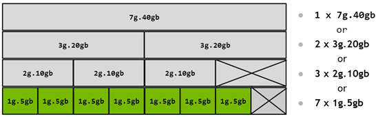
Figure 7 MIG Profiles on A100#
In this diagram, a valid combination can be built by starting with an instance profile on the left and combining it with other instance profiles as you move to the right, such that no two profiles overlap vertically. For a list of all supported combinations and placements of profiles on A100 and A30, refer to the section on supported profiles.
Note that prior to NVIDIA driver release R510, the combination of a (4 memory, 4 compute) and a (4 memory, 3 compute) profile was not supported. This restriction no longer applies on newer drivers.
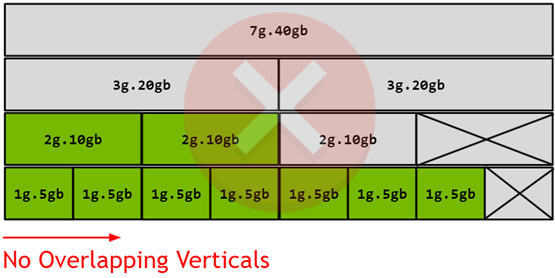
Figure 8 Profile Placements on A100#
Note that the diagram represents the physical layout of where the GPU Instances will exist once they are instantiated on the GPU. As GPU Instances are created and destroyed at different locations, fragmentation can occur, and the physical position of one GPU Instance will play a role in which other GPU Instances can be instantiated next to it.
CUDA Concurrency Mechanisms#
MIG has been designed to be largely transparent to CUDA applications - so that the CUDA programming model remains unchanged to minimize programming effort. CUDA already exposes multiple technologies for running work in parallel on the GPU and it is worthwhile showcasing how these technologies compare to MIG. Note that streams and MPS are part of the CUDA programming model and thus work when used with GPU Instances.
CUDA Streams are a CUDA Programming model feature where, in a CUDA application, different work can be submitted to independent queues and be processed independently by the GPU. CUDA streams can only be used within a single process and don’t offer much isolation - the address space is shared, the SMs are shared, the GPU memory bandwidth, caches and capacity are shared. And lastly any errors affect all the streams and the whole process.
MPS is the CUDA Multi-Process service. It allows co-operative multi process applications to share compute resources on the GPU. It’s commonly used by MPI jobs that cooperate, but it has also been used for sharing the GPU resources among unrelated applications, while accepting the challenges that such a solution brings. MPS currently does not offer error isolation between clients and while streaming multiprocessors used by each MPS client can be optionally limited to a percentage of all SMs, the scheduling hardware is still shared. Memory bandwidth, caches and capacity are all shared between MPS clients.
Lastly, MIG is the new form of concurrency offered by NVIDIA GPUs while addressing some of the limitations with the other CUDA technologies for running parallel work.
Streams |
MPS |
MIG |
|
|---|---|---|---|
Partition Type |
Single Process |
Logical |
Physical |
Max Partitions |
Unlimited |
48 |
7 |
SM Performance Isolation |
No |
Yes (by percentage, not partitioning) |
Yes |
Memory Protection |
No |
Yes |
Yes |
Memory Bandwidth QoS |
No |
No |
Yes |
Error Isolation |
No |
No |
Yes |
Cross-Partition Interop |
Always |
IPC |
Limited IPC |
Reconfigure |
Dynamic |
Process Launch |
When Idle |