

Optimizing IO Performance#
NUMA Affinity#
Important
On Vera-Rubin platforms, it’s critical that you use numactl to bind
your IO applications to the local CPU and memory that are in the same NUMA
domain as your IO devices.
To check your network adapter’s NUMA domain, run following commands:
cat /sys/class/net/<ethernet interface>/device/numa_node
cat /sys/class/net/<ethernet interface>/device/local_cpulist
To check your NVMe drive’s NUMA domain, run following commands:
cat /sys/class/nvme/<NVMe device>/device/numa_node
cat /sys/class/nvme/<NVMe device>/device/local_cpulist
After you determine the NUMA node for your IO devices, use numactl to bind your IO applications to the CPU and memory in the same NUMA domain as your IO devices.
Refer to CPU NUMA Affinity for more information about using numactl.
PCIe Peer-to-Peer Bandwidth#
A PCIe peer-to-peer (P2P) transfer that crosses the socket boundary travels over the C2C die-to-die link between the two Vera sockets. Cross-socket P2P writes are subject to a bandwidth limit that local P2P traffic is not.
The maximum remote socket P2P write bandwidth is 54 GB/s per destination x16 PCIe instance. This is the cumulative bandwidth of the remote socket P2P writes that arrive at that destination from all PCIe sources on the other socket.
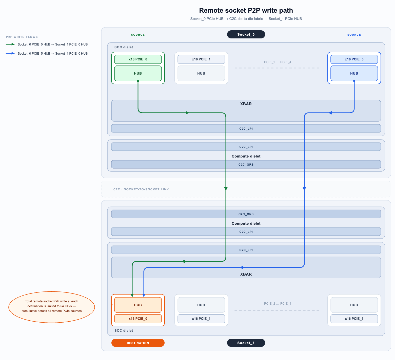
Remote P2P writes from two Socket_0 sources converge on one Socket_1 destination. The 54 GB/s limit applies to the cumulative write bandwidth that arrives at that destination.#
The limit applies per destination and is not shared between destinations. Each x16 PCIe destination can simultaneously sink up to 54 GB/s of remote socket P2P writes.
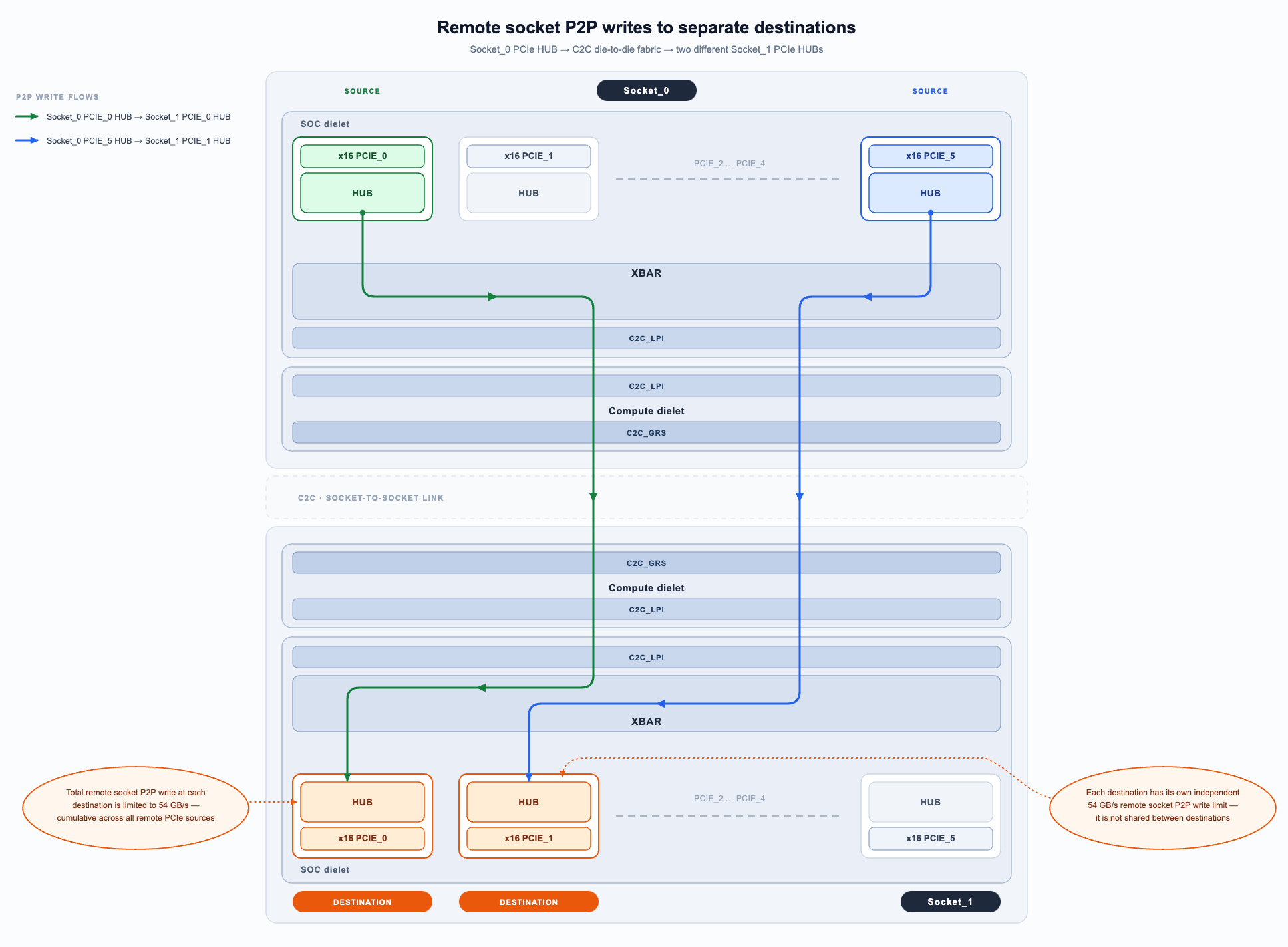
Remote P2P writes from Socket_0 to two different Socket_1 destinations, and each destination has its own 54 GB/s limit.#
Remote socket P2P reads are not affected and stream at the full x16 Gen6 PCIe rate to each destination. Local socket P2P reads and writes stay within one socket, never cross the C2C link, and also run at the full x16 Gen6 rate.
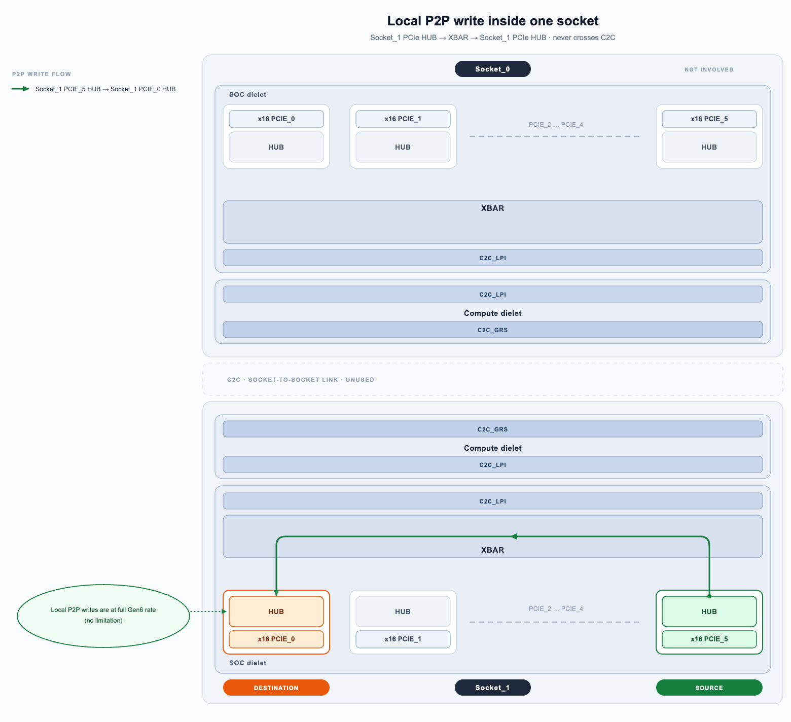
Local P2P write inside Socket_1, from PCIE_5 OCU through UCF_SOC to PCIE_0 EPOC. The traffic never crosses C2C and runs at full x16 Gen6 rate.#
The following table summarizes the peer-to-peer bandwidth limits:
Traffic |
Scope |
Limit |
|---|---|---|
P2P write |
Remote socket |
54 GB/s per destination x16 instance, cumulative from all remote socket sources |
P2P read |
Remote socket |
Full x16 Gen6 rate per destination |
P2P write |
Local socket |
Full x16 Gen6 rate |
P2P read |
Local socket |
Full x16 Gen6 rate |
PCIe Relaxed Ordering#
Enabling PCIe Relaxed Ordering (RO=1) on your PCIe devices improves the performance of device traffic to system memory and to GPU memory. The benefit applies to local traffic and to traffic that crosses the socket boundary, and it grows with the distance that the traffic travels.
PCIe ordering rules are maintained across the CPU fabric and, for cross-socket traffic, across the C2C link between the two Vera sockets. When Relaxed Ordering is disabled (RO=0), which the PCIe specification calls Default Ordering, all writes must maintain global visibility of write-after-write across addresses and destinations which adds additional overhead. Relaxed Ordering allows better overlap of writes because global visibility does not need to be strictly maintained across different addresses. The additional overhead of RO=0 write-after-write ordering might increase the observed latency for Read transactions.
Important
Systems that run workloads with sustained cross-socket traffic to NVMe drives are required to enable PCIe Relaxed Ordering.
This setting helps optimize PCIe transaction handling under high-bandwidth traffic conditions and reduces the likelihood of completion timeouts (CTO) and downstream port containment (DPC) that might be reported by NVMe and ConnectX-9 devices during stress testing.
Enabling Relaxed Ordering depends on the endpoint:
Network adapters: Relaxed Ordering is requested by the application or the driver on each memory region that it registers. On NVIDIA network adapters, this is the
per_mkeydefault, and NVIDIA recommends that you keep it. To check the setting, setADVANCED_PCI_SETTINGStoTrueand run the following command:sudo mlxconfig -d <dev> query | grep PCI_WR_ORDERING PCI_WR_ORDERING per_mkey(0)
Verify that your workload requests Relaxed Ordering on the memory regions that it registers. The GPU communication libraries, and the benchmarks that are distributed with them, already do this.
NVMe drives: Relaxed Ordering is controlled by the drive firmware. Contact your SSD vendor for the firmware version and the configuration that enable it on your drives.
Note
Relaxed Ordering is not a substitute for NUMA affinity. Bind your IO applications to the socket that owns the device first, as described in NUMA Affinity, and enable Relaxed Ordering for the workloads that must cross the socket boundary.
Networking#
NVIDIA recommends that you download the latest driver and firmware for your network adapter. Before making any changes, contact your network adapter’s vendor for information about whether the tuning options in this guide are applicable.
Prerequisites for System Tuning#
Before you tune at the network level, apply the following system-level tunings, which directly affect networking workloads:
Power and thermals: Networking workloads, especially at high packet rates, are sensitive to CPU frequency and throttling. Keeping the system out of power-saving and thermal-throttling states gives consistent per-packet processing time, higher throughput, and lower, more stable latency. Refer to Power and Thermals for more information.
NUMA affinity: Run network threads on cores, and allocate their buffers in memory, that are local to the NIC. This avoids cross-NUMA traffic, which adds latency and reduces achievable bandwidth. Refer to NUMA Affinity for more information.
Recommended Performance Tools#
Use the following tools, which are part of the NVIDIA DOCA SDK and are available on the DOCA Developer Zone, for benchmarking and analysis:
doca-perftest: RDMA benchmarking for single-node and multi-node setups. It measures bandwidth, message rate, and latency.
ngauge: NIC-level performance analysis. It samples NIC hardware counters so that you can analyze and debug network performance.
To confirm the effect of the tunings in this section on your workload, measure with these tools before and after you apply them.
GPU-NIC Affinity#
Configure GPU networking workloads to use the NICs that are assigned to each
GPU in the applicable NVIDIA reference architecture (RA). Completing these
assignments provides redundancy and load balancing. To see the platform
topology and to check that your assignment matches it, run
nvidia-smi topo -m.
doca-perftest detects GPU-NIC affinity automatically. For other tools, or
when you select devices manually, use the following rules.
Identifying the NIC Type#
The node has two kinds of NICs, and only one kind is meant for GPU traffic:
ConnectX-9 SuperNIC (east-west): The Spectrum-X or InfiniBand NIC. Most GPU traffic goes through these NICs.
BlueField-4 DPU (north-south): Management and remote storage. Do not use these devices for GPU benchmarks.
To see which mlx5_* device is which, run ibdev2netdev -v. The
description names the model, ConnectX-9 SuperNIC or BlueField-4.
Selecting the NIC for Each GPU#
In the nvidia-smi topo -m matrix, select a ConnectX-9 NIC whose affinity to
the GPU shows NODE, which provides the best performance. A NIC that shows
SYS also works, but its traffic crosses the inter-socket link, so expect
lower performance. The IB device name for each NIC is in the NIC Legend at the
bottom of the output, for example, NIC0: mlx5_0.
Note
NODE is the recommended pairing from the system point of view.
Determining which NIC is best out of the set of NODE NICs depends on
the InfiniBand or Spectrum-X reference architecture. When you select a NIC,
follow the reference architecture for your deployment.
Run the following command:
nvidia-smi topo -m
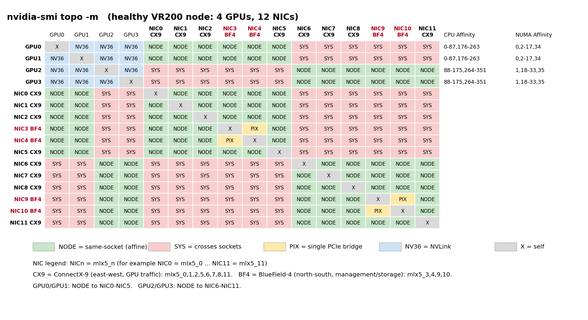
Expected nvidia-smi topo -m output on a healthy Vera-Rubin NVL72 node.#
In the output on a healthy Vera-Rubin NVL72 node:
GPU0 and GPU1 are on the first socket, CPU cores 0-87 and 176-263. GPU2 and GPU3 are on the second socket, CPU cores 88-175 and 264-351. All GPUs are connected with
NV36.The ConnectX-9 NICs are
mlx5_0,mlx5_1,mlx5_2,mlx5_5,mlx5_6,mlx5_7,mlx5_8, andmlx5_11. The BlueField-4 devices, which are two dual-port DPUs, aremlx5_3,mlx5_4,mlx5_9, andmlx5_10.GPU0 and GPU1 have
NODEaffinity to NIC0-NIC2, and NIC5, which are the ConnectX-9 devicesmlx5_0,mlx5_1,mlx5_2, andmlx5_5. GPU2 and GPU3 haveNODEaffinity to NIC6-NIC8, and NIC11, which are the ConnectX-9 devicesmlx5_6,mlx5_7,mlx5_8, andmlx5_11.NODEis the closest GPU-NIC relationship on this platform and provides the best performance. You can useSYSNICs, with lower expected performance.PIXappears only between the two ports of each BlueField-4, NIC3-NIC4 and NIC9-NIC10.Pin processes to the CPU cores that are listed for the GPU’s socket, as described in NUMA Affinity.
Storage/Filesystem#
This section provides information about performance tunings that are related to storage and the filesystem. The performance metrics for storage are:
Throughput: For large requests, throughput is reported using units such as MB/s or GB/s. For small requests, the unit is IOPS (Input/Output Operations Per Second).
Latency: Time to complete a request.
Preconditioning an SSD#
SSD performance depends on its previous write history. For reproducible, device-level results, establish a defined initial state and condition the test range before collecting measurements. Here is a typical sequence for a write benchmark:
Perform two full sequential writes across the test range.
Run the target workload, such as random writes, until performance reaches steady state.
If fio v3.41 or later is available, you can use sprandom to reach steady state more quickly for a random write workload. In the following example, the fio job uses sprandom to precondition for a 4kB Random Write workload:
[global]
ioengine=io_uring
direct=1
bs=4k
iodepth=256
numjobs=1
rw=randwrite
norandommap
randrepeat=0
size=100%
sprandom=1
spr_num_regions=400
spr_op=0.18

[nvme0n1]
filename=/dev/nvme0n1
Refer to Sample fio Job Files for NVMe SSDs for more information about using fio.
Note
The spr_op=0.18 setting applies generally to TLC drives. For QLC drives,
NVIDIA recommends that you use spr_op=0.22 or consult the
Overprovisioning specifications published by the SSD vendor.
Warning
Preconditioning overwrites data in the test range, so use only a device or namespace whose contents can be destroyed.
Refer to the SNIA Solid State Storage Performance Test Specification for more information about standardized preconditioning and steady-state criteria.
Drop Page Cache#
When files are read from storage into memories on a Linux system, they are cached in unused memory areas called page cache. To drop the page cache, for example, because you want to benchmark the storage subsystem, you might need to drop the page cache before every test to see true storage performance.
To drop the page cache, run the following command:
# Write out dirty pages to disk(s)
sudo sync
# Drop page cache, dentries, and inodes
echo 3 | sudo tee /proc/sys/vm/drop_caches
To compare how much memory area has been released from dropping the page cache, compare the Cached: line in the output of following command before and after invoking the previous command:
cat /proc/meminfo | grep Cached
Sample fio Job Files for NVMe SSDs#
This section provides sample fio job files for benchmarking performance of NVMe SSDs using the Flexible IO Tester (fio) benchmark.
The sample files are configured to use the io_uring engine and allow
pinning the requesting cores to the local socket using the cpus_allowed
parameter. The job performs random reads of 4K blocks on two NVMe SSDs
concurrently.
The CPU and NUMA node values in the following job file match the sample dual-socket topology in Checking the Non-Uniform Memory Access Settings. Before you run the job, replace these values with the topology reported for your system and devices.
The number of IO requests in flight can be tuned by adjusting the iodepth and numjobs parameters. Typically, for small requests (for example, 4K) higher values for iodepth and numjobs are used to keep the device busy. In the following example, the fio job uses four threads per SSD and 256 requests per thread:
[global]
ioengine=io_uring
direct=1
bs=4k
iodepth=256
numjobs=4
thread=1
group_reporting=1
runtime=60
time_based=1
ramp_time=5
rw=randread
norandommap=1
randrepeat=0
cpus_allowed_policy=split

[nvme0n1]
# nvme0 is attached to socket 0
filename=/dev/nvme0n1
cpus_allowed=0-3
numa_mem_policy=bind:0

[nvme1n1]
# nvme1 is attached to socket 1
filename=/dev/nvme1n1
cpus_allowed=88-91
numa_mem_policy=bind:1
Tuning Performance for NVMe SSDs#
To ensure that SSDs hit peak performance on Vera, consider the following factors:
Minimize the overhead of interrupt handling by coalescing interrupts for NVMe devices or by using polling.
Minimize the overhead of IOMMU translations by using lazy invalidations.
To keep the device busy, ensure that there are a sufficient number of requests in flight.
Minimize cross-socket traffic by pinning the cores performing IO operations to the local socket(s). Refer to the
cpus_allowedandnuma_mem_policyfields in the sample fio job file for more information.
Interrupt Coalescing for NVMe SSDs#
For NVMe SSDs, interrupt coalescing reduces the interrupt overhead by generating an interrupt after a batch of requests have been completed. As per the NVMe specification:
Aggregation Time (TIME): Specifies the recommended maximum time in 100 microsecond increments that a controller might delay an interrupt due to interrupt coalescing. A value of 0h means there is no delay. The controller might apply this time to each interrupt vector or across all interrupt vectors. The reset value of this setting is 0h.
Aggregation Threshold (THR): Specifies the recommended minimum number of completion queue entries to aggregate each interrupt vector before signaling an interrupt to the host. This is an 0-based value, and the reset value of this setting is 0h.
To request an aggregation threshold of eight completion queue entries per interrupt vector, and a maximum aggregation time of 100 microseconds, run the following command:
# For NVMe drive nvme0n1
sudo nvme set-feature /dev/nvme0n1 -f 0x8 -V 0x00000107

# Check the setting
sudo nvme get-feature /dev/nvme0n1 -f 0x8 -H

get-feature:0x08 (Interrupt Coalescing), Current value:0x00000107
    Aggregation Time     (TIME): 100 usec
    Aggregation Threshold (THR): 8
Lazy IOMMU Invalidations#
Lazy IOMMU invalidation is a kernel feature that amortizes the overhead of
IOMMU cache flushes over multiple IO requests, and it applies only when the IOMMU
translates DMA. In the IOMMU passthrough mode, DMA translation and its associated
invalidations are bypassed, so iommu.strict does not provide an additional
performance benefit.
To check the active IOMMU mode, run the following command:
sudo dmesg | grep -i iommu | grep -i 'passthrough\|strict\|lazy'
If the system uses translated DMA, boot the kernel with the iommu.strict=0
kernel parameter to request lazy invalidation. This can improve IO throughput
at the cost of reduced device isolation. The IOMMU driver falls back to strict
mode if it does not support lazy invalidation.
Refer to Input-Output Memory Management Unit Passthrough for more information about selecting the IOMMU mode.
Enabling the Polling-Based Completion on NVMe SSDs#
To enable polling-based completion:
Configure the Linux
nvmekernel module to use polling for a subset of IO queues:# Edit /etc/modprobe.d/nvme.conf - each NVMe device will have 16 queues with polling enabled (no interrupts) options nvme poll_queues=16
Update the initramfs. For example, on Ubuntu 26.04:
sudo dracut --force
Reboot the system.
Add the following lines to the
globalsection of the fio job file:hipri=1 fixedbufs=1
I/O Scheduler for NVMe SSDs#
For raw NVMe benchmarking, use the Linux none I/O scheduler to minimize
block-layer scheduling overhead. NVMe devices already perform their own
queueing, and none ensures that fio results reflect device and
platform performance instead of the scheduler behavior.
To check the current scheduler:
cat /sys/block/<nvme_device>/queue/scheduler
The active scheduler is shown in brackets, for example:
[none] mq-deadline
To set the scheduler to none before running benchmarks:
echo none | sudo tee /sys/block/<nvme_device>/queue/scheduler
This setting is per device and does not persist across reboots unless configured through system policy, such as a udev rule.
NUMA Affinity for RAID Array#
As mentioned in NUMA Affinity section, on Vera-Rubin platforms, it is critical for your IO applications to bind to local CPU and memory. To create a software RAID array for your SSDs on a Vera-Rubin platform, it’s important that you create a separate RAID array for the SSDs attached to each CPU socket.
When accessing these RAID arrays, bind your applications using numactl
to the CPU and memory that are on the same NUMA domain as each RAID array.
Refer to CPU NUMA Affinity for more information about using numactl.