Initial Cluster Setup#
This document details how to deploy NVIDIA Base Command™ Manager (BCM) on NVIDIA DGX BasePOD™ configurations.
Physical installation and network switch configuration must be completed before deploying BCM. In addition, information about the intended deployment should be recorded in a site survey.
The deployment stage of a DGX BasePOD consists of using BCM to provision and manage the Kubernetes cluster.
Configure the DGX systems to PXE boot by default.
Using either KVM or a crash cart, connect to the DGX system, enter the BIOS menu, and configure Boot Option #1 to be [NETWORK].
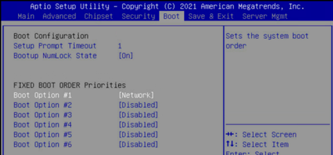
Ensure that other Boot Options are [Disabled] and navigate to the UEFI NETWORK Drives BBS Priorities menu.
Set Boot Option #1 and Boot Option #2 to use IPv4 for Storage 4-2 and Storage 5-2.
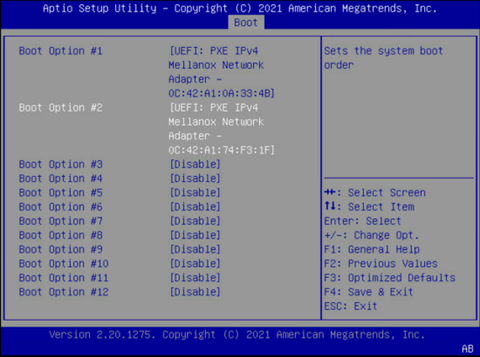
Ensure that other Boot Options are [Disabled].
Select Save & Exit.
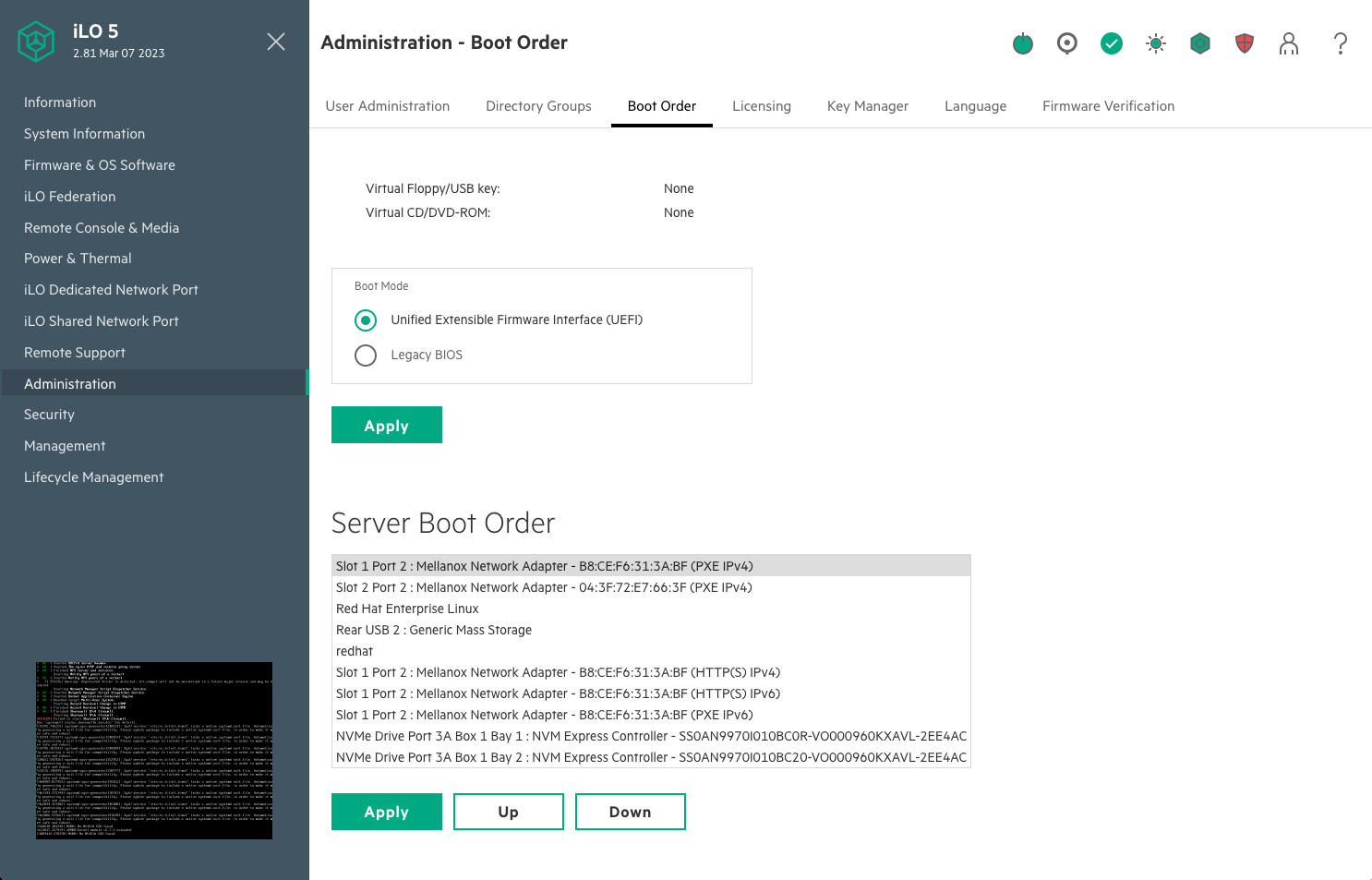
On the failover head node and the management nodes, ensure that Network boot is configured as the primary option. Ensure that the Mellanox ports connected to the network on the head and CPU nodes are set to Ethernet mode as well.
This is an example of a system that will boot from the network with Slot 1 Port 2 and Slot 2 Port 2.
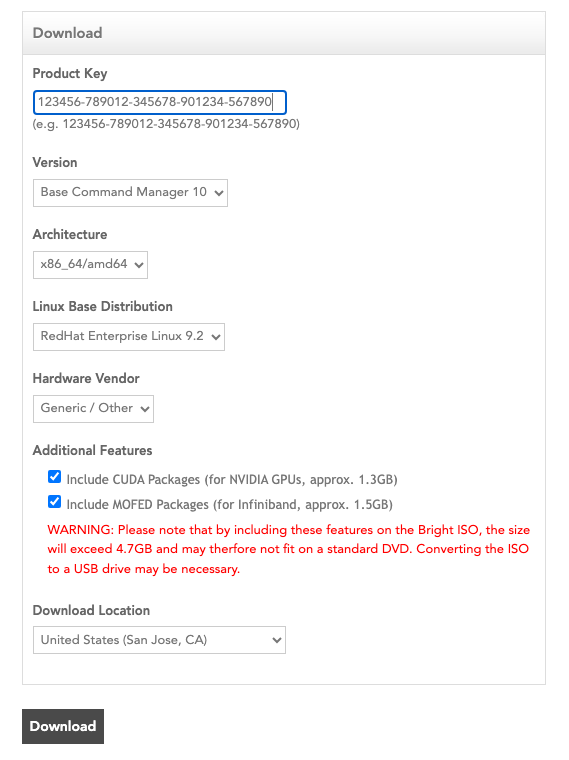
Download a BCM ISO from the Bright Download site. Select Base Command Manager 10, RHEL 9.2 and check the Include NVIDIA CUDA Packages and MOFED packages checkbox.
Burn the ISO to a DVD or a bootable USB device.
It can also be mounted as virtual media and installed using the BMC. The specific mechanism for the latter will vary by vendor.
Ensure that the BIOS of the target head node is configured in UEFI mode and that its boot order is configured to boot the media containing the BCM installer image.
Boot the installation media.
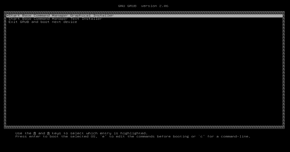
At the grub menu, choose Start Base Command Manager Graphical Installer.
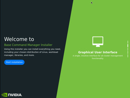
Select Start installation on the splash screen.
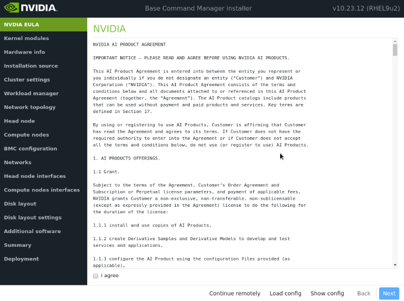
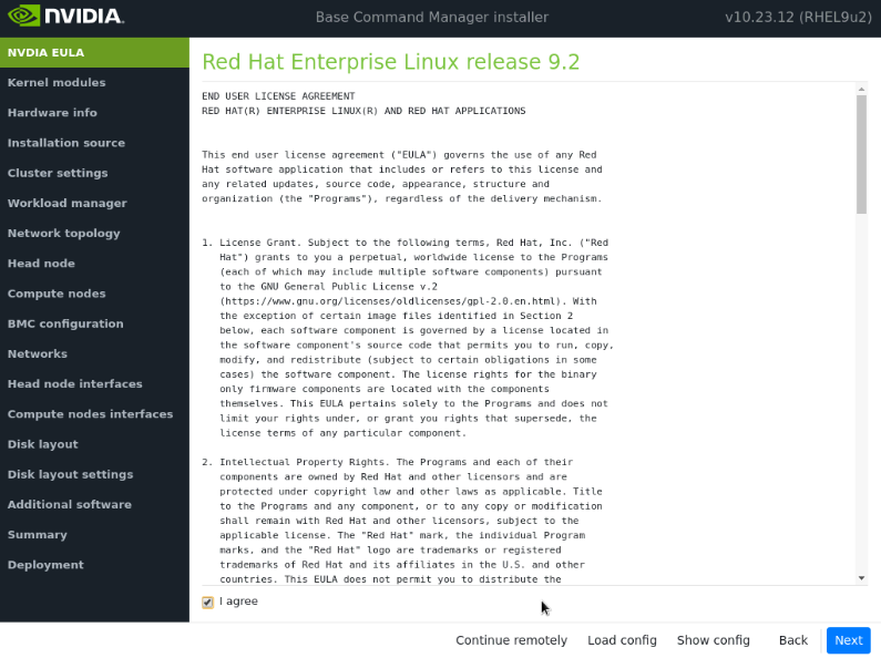
Accept the terms of the NVIDIA EULA by checking I agree and then select Next.
Accept the terms of the Ubuntu Server UELA by checking I agree and then select Next.
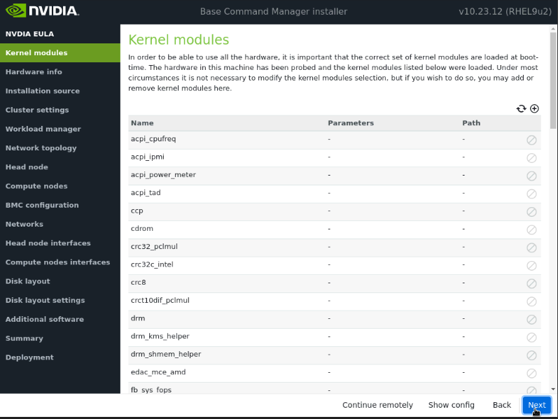
Unless instructed otherwise, select Next without modifying the kernel modules to be loaded at boot time.
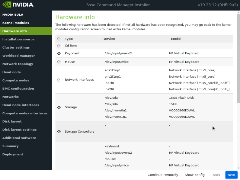
Verify the Hardware info is correct and then select Next.
For example, the target storage device and the cabled host network interfaces are present (in this case three NVMe drives are the target storage device, and ens1np0 and ens2np01 are the cabled host network interfaces).
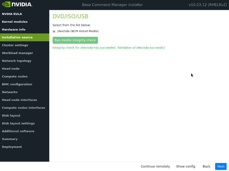
On the Installation source screen, choose the appropriate source and then select Next.
Running a media integrity check is optional.
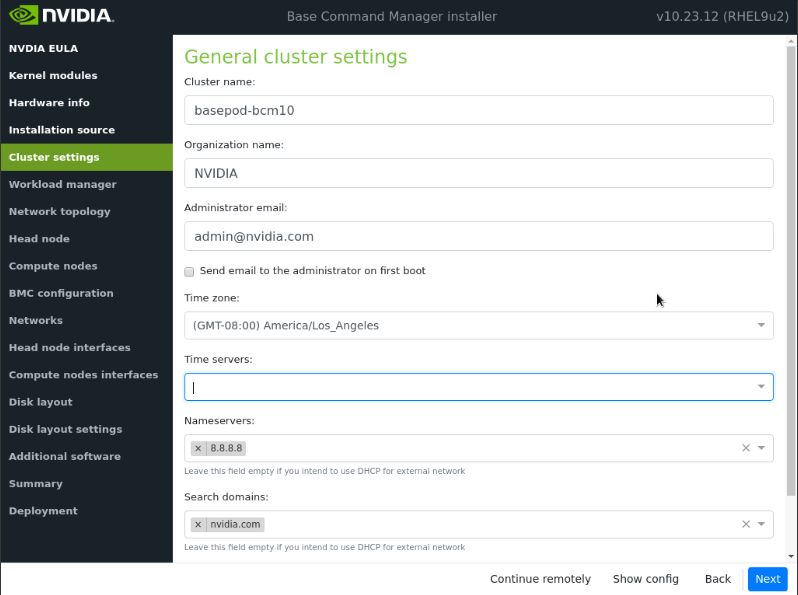
On the Cluster settings screen, enter the required information and then select Next.
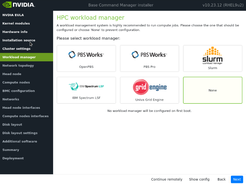
On the Workload manager screen, choose None and then select Next.
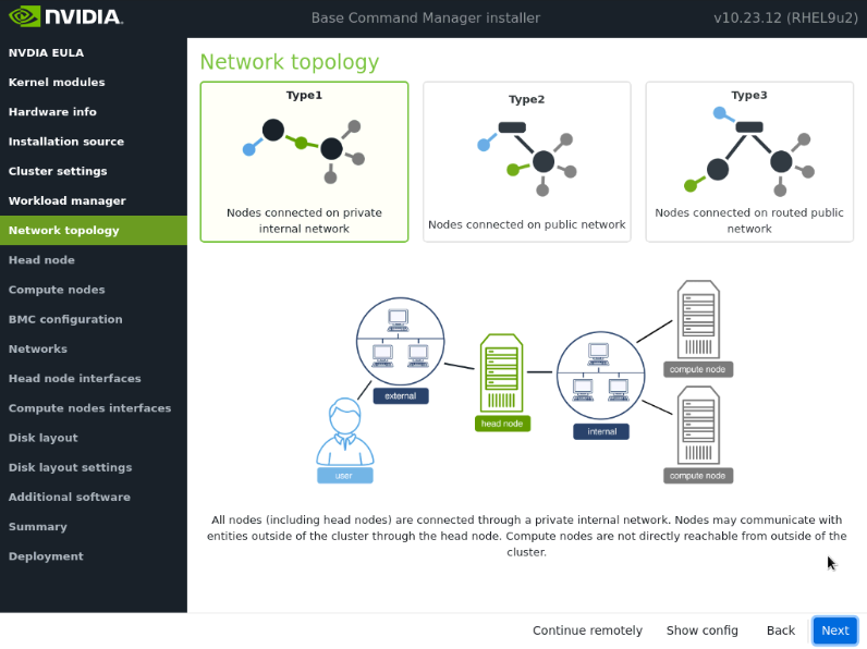
On the Network topology screen, choose the network type for the data center environment and then select Next.
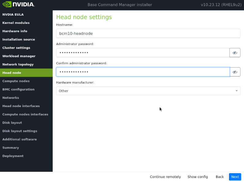
On the Head node screen, enter the Hostname, and Administrator password, choose Other for Hardware manufacturer, and then select Next.
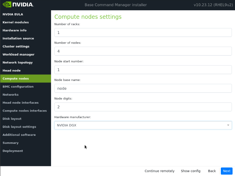
Adjust the node digits to 2 in the Compute Node Settings and then select Next.
Ensure that the Node base name is node. Other values will be updated later in the installation.
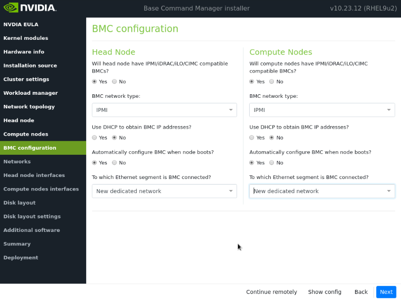
On the BMC Configuration screen, choose Yes for both Head Node and Compute Nodes. Follow the screenshot below for the rest of the configuration. Then select Next.
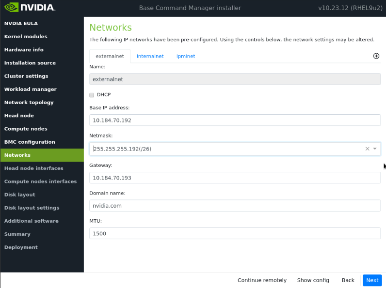
On the Networks screen, enter the required information for externalnet, and then select Next.
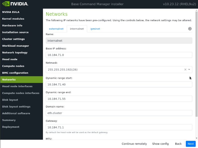
Navigate to the internalnet tab and enter the required information for internalnet, leaving the MTU values at their defaults, and then select Next.
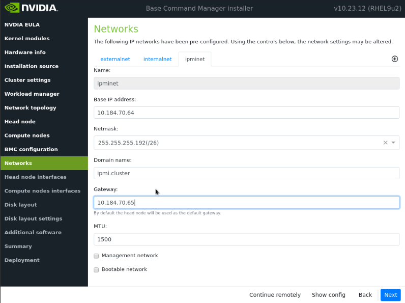
Navigate to the ipminet tab, enter the required information for ipminet, and then select Next.
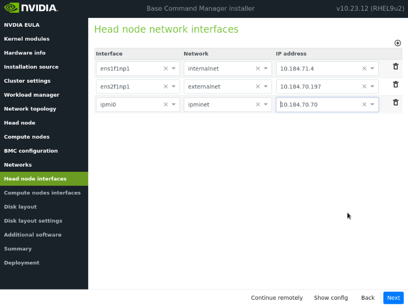
On the Head node interfaces screen, ensure that one interface is configured with the head node’s target internalnet IP, and then select Next.
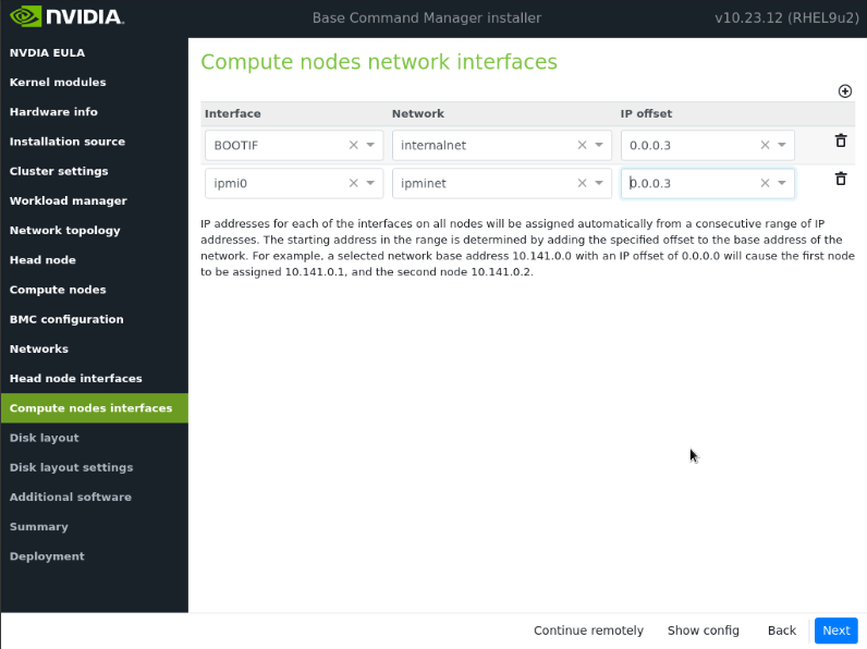
On the Compute node interfaces screen, change the offset to 0.0.0.3, and then select Next.
These will be updated post-installation.
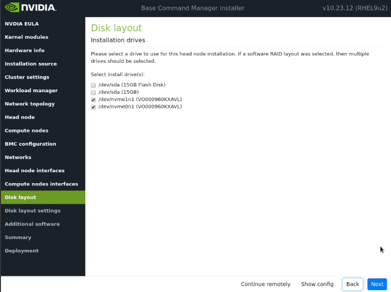
On the Disk layout screen, select the target install location and then select Next.
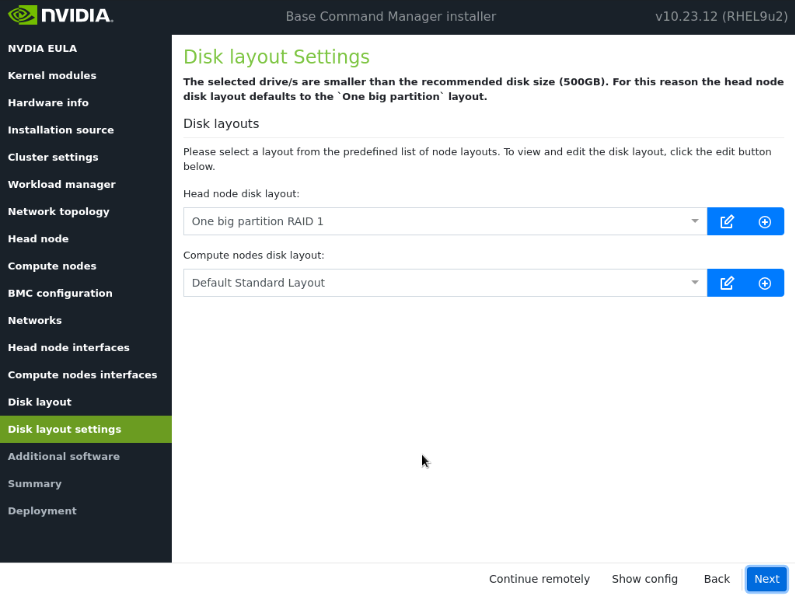
On the Disk layout settings screen, select One Big Partition for the Headnode, and Default Standard Layout for the compute nodes. Then select Next.
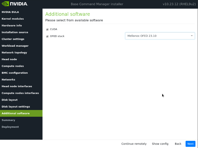
In the Additional software screen, select CUDA and MOFED 23.10, then select Next.
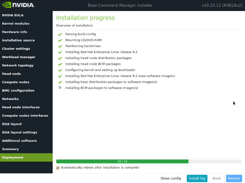
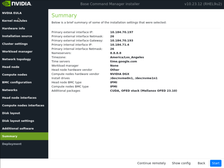
Confirm the information on the Summary screen and then select Next.
The Summary screen provides an opportunity to confirm the Head node and basic cluster configuration before deployment begins. This configuration will be updated/modified for DGX BasePOD after deployment is complete. If values do not match expectations, use the Back button to navigate to the appropriate screen to correct any mistake.
Once the deployment is complete, select Reboot.