Cluster Bring Up#
This section addresses configuration steps to be performed on Base Command Manager headnode1.
Enable DeviceResolveAnyMAC#
The following section enables provisioning of the bonded interfaces on downstream appliances/nodes.
This process enables failover PXE booting for bonded interfaces.
Edit /cm/local/apps/cmd/etc/cmd.conf and add the following line
AdvancedConfig = { "DeviceResolveAnyMAC=1" } # modified value
Example:
nano /cm/local/apps/cmd/etc/cmd.conf
GNU nano 6.2
# Set one or more advanced config parameters, only do this when needed
# AdvancedConfig = { "param=value", "param=value" }
AdvancedConfig = { "DeviceResolveAnyMAC=1" } # modified value
Once the above parameter has been saved restart the CMDaemon
root@bcm10-headnode:~# systemctl restart cmd
Define Cluster Networks#
Next we’ll add and configure the additional networks needed for BasePOD.
Refer to Site Survey for the details.
Change network names#
First we will change the default network names to align with the names defined in Networking section under Overview.
root@bcm10-headnode1:~# cmsh
[bcm10-headnode1]% network
[bcm10-headnode1->network]% list
Name (key) Type Netmask bits Base address Domain name IPv6
--------------------------------------------------------------
globalnet Global 0 0.0.0.0 cm.cluster
internalnet Internal 24 10.184.94.0 eth.cluster
ipminet Internal 24 10.160.6.0 ipmi.cluster
[bcm10-headnode1->network]% use internalnet
[bcm10-headnode1->network[internalnet]]% set name managementnet
[bcm10-headnode1->network*[managementnet*]]% ..
[bcm10-headnode1->network*]% use ipminet
[bcm10-headnode1->network*[ipminet]]% set name oobmanagementnet
[bcm10-headnode1->network*[oobmanagementnet*]]% ..
[bcm10-headnode1->network*]% commit
Successfully committed 2 Networks
[bcm10-headnode1->network]% list
Name (key) Type Netmask bits Base address Domain name IPv6
--------------------------------------------------------------
globalnet Global 0 0.0.0.0 cm.cluster
managementnet Internal 24 10.184.94.0 eth.cluster
oobmanagementnet Internal 24 10.160.6.0 ipmi.cluster
Computenet Config#
Starting with computenet, to facilitate gpu to gpu RDMA communication.
root@bcm10-headnode1:~# cmsh
[bcm10-headnode1]% network
[bcm10-headnode1]% add computenet
[bcm10-headnode1->network*[computenet*]]% set domainname ib.compute
[bcm10-headnode1->network*[computenet*]]% set baseaddress 100.126.0.0
[bcm10-headnode1->network*[computenet*]]% set netmaskbits 16
[bcm10-headnode1->network*[computenet*]]% commit
Storagenet Config#
Ethernet (tcp) Storage
BasePOD typically has Ethernet attached Block Storage solutions to the managementnet (internalnet).
In such scenarios it is not necessary to define any additional networks.
IB Storage#
In the event IB Storage is attached to the cluster an additional Infiniband network will need to be defined using the following commands.
[bcm10-headnode1->network[computenet]]% clone computenet storagenet
[bcm10-headnode1->network*[storagenet*]]% set domainname ib.storage
[bcm10-headnode1->network*[storagenet*]]% set baseaddress 100.127.0.0
[bcm10-headnode1->network*[storagenet*]]% commit
Verify using cmsh CLI
[bcm10-headnode1]% home;network;list -f
name:20,type:10,netmaskbits:10,baseaddress:15,domainname:20
name (key) type netmaskbit baseaddress domainname
-------------------------------------------------------
computenet Internal 16 100.64.0.0 ib.compute
managementnet Internal 24 10.184.94.0 eth.cluster
oobmanagementnet Internal 24 10.160.6.0 ipmi.cluster
Enable Out-of-band Management of Cluster Nodes#
Set the BMC Username and Password for all BCM managed nodes
cmsh
[bcm10-headnode1]% partition
[bcm10-headnode1->partition[base]% bmcsettings
[bcm10-headnode1->partition[base]->bmcsettings]% set username bright
[bcm10-headnode1->partition[base]->bmcsettings*]% set password FUNKYpassW0rdGo3sH3r3
[bcm10-headnode1->partition[base]->bmcsettings*]% commit
DGX Node Bringup#
Software Image Setup for DGX’s#
Next we’ll create a backup image of the DGX software image on the headnode.
This is a safety step which lets us make changes to the in-use image, and revert back to a factory DGX OS image in the event that something goes wrong.
cmsh
[bcm10-headnode]% softwareimage
[bcm10-headnode->softwareimage]% clone dgx-os-6.2-h100-image dgx-os-6.2-h100-image-orig
[bcm10-headnode->softwareimage*[dgx-os-6.2-h100-image-orig*]]% commit
DGX Node category setup#
Next, we’re going to define the DGX node identities in BCM.
All of the DGX nodes in the DGX BasePOD will be named using the following naming convention “dgx-xx”, this helps differentiate them from the other nodes.
We’ll first start by defining dgx-01’s node identity and DGX node category
cmsh
[bcm10-headnode]% device
[bcm10-headnode->device]% clone node01 dgx-01
[bcm10-headnode->device*[dgx-01*]]% set category dgx-h100
[bcm10-headnode->device*[dgx-01*]]% commit
DGX Interface Definitions#
Consult the site survey for the specific interface/IP addresses to assign to DGX nodes.
First we’ll define the BMC and managementnet bond interfaces
[bcm10-headnode1->device*[dgx-01*]]% interfaces
[bcm10-headnode1->device*[dgx-01*]->interfaces]% set ipmi0 ip 10.160.6.31
[bcm10-headnode1->device*[dgx-01*]->interfaces*]% set ipmi0 network oobmanagementnet
[bcm10-headnode1->device*[dgx-01*]->interfaces*]%
[bcm10-headnode1->device*[dgx-01*]->interfaces*[ipmi0*]]% add physical enp170s0f1np1; add physical enp41s0f1np1
[bcm10-headnode1->device*[dgx-01*]->interfaces*[enp41s0f1np1*]]% add bond bond0 10.133.15.31 managementnet
[bcm10-headnode1->device*[dgx-01*]->interfaces*[bond0*]]% append interfaces enp170s0f1np1 enp41s0f1np1
[bcm10-headnode1->device*[dgx-01*]->interfaces*[bond0*]]% ..
[bcm10-headnode1->device*[dgx-01*]->interfaces*]% remove bootif
[bcm10-headnode1->device*[dgx-01*]->interfaces*]% ..
[bcm10-headnode1->device*[dgx-01*]]% set provisioninginterface bond0
[bcm10-headnode1->device*[dgx-01*]]% commit
Now add the ib interface definitions for the compute fabric
[bcm10-headnode->device*[dgx-01*]->interfaces[bond0]]% add physica ibp220s0 100.126.0.31 computenet
[bcm10-headnode->device*[dgx-01*]->interfaces*[ibp154s0*]]% foreach -o ibp220s0 ibp154s0 ibp206s0 ibp192s0 ibp24s0 ibp64s0 ibp79s0 ibp94s0 ()
[bcm10-headnode->device*[dgx-01*]->interfaces*]% set ibp154s0 ip 100.126.1.31
[bcm10-headnode->device*[dgx-01*]->interfaces*]% set ibp206s0 ip 100.126.2.31
[bcm10-headnode->device*[dgx-01*]->interfaces*]% set ibp192s0 ip 100.126.3.31
[bcm10-headnode->device*[dgx-01*]->interfaces*]% set ibp79s0 ip 100.126.4.31
[bcm10-headnode->device*[dgx-01*]->interfaces*]% set ibp64s0 ip 100.126.5.31
[bcm10-headnode->device*[dgx-01*]->interfaces*]% set ibp94s0 ip 100.126.6.31
[bcm10-headnode->device*[dgx-01*]->interfaces*]% set ibp24s0 ip 100.126.7.31
[bcm10-headnode->device*[dgx-01*]->interfaces*]% commit
Defining the storage fabric:#
Ethernet (tcp)#
For Ethernet attached block storage solutions no additional network interface definitions are necessary as the interface used will be the bond0 bonded interface.
Infiniband (o2ib)#
For Infiniband attached block storage solutions run the following commands to define the 2 additional storagenet interfaces for the DGX appliance.
[bcm10-headnode->device[dgx-01]->interfaces]% add physical ibp170s0f0 100.127.0.31 storagenet
[bcm10-headnode->device*[dgx-01*]->interfaces*[ibp170s0f0*]]% add physical ibp41s0f0 100.127.1.31 storagenet
[bcm10-headnode->device*[dgx-01*]->interfaces*[ibp41s0f0*]]% commit
[bcm10-headnode->device[dgx-01]->interfaces[ibp41s0f0]]% exit
Define DGX-01’s MAC address#
Here we are going to assign MAC addresses to the two managementnet (internalnet) attached interfaces that belong to bond0.
When assigning MAC address there is no specific order/requirement of which MAC goes to which enumerated interface name, so long as both MAC addresses are recorded for the appropriate DGX node identity
Refer to site survey for interface MAC details.
[bcm10-headnode->device[dgx-01]->interfaces]% set enp170s0f1np1 mac 94:6D:00:00:00:FB
[bcm10-headnode->device*[dgx-01*]->interfaces*]% set enp41s0f1np1 mac 94:00:00:00:74:0B
[bcm10-headnode->device*[dgx-01*]->interfaces*]% exit
[bcm10-headnode->device*[dgx-01*]]% set mac 94:6D:00:00:00:FB
[bcm10-headnode->device*[dgx-01*]]% commit
Test Provisioning of DGX-01#
DGX-01 is now ready to be provisioned. It can be powered on using the physical power button, by using the BMC, or via IPMI tool command from the Headnode.
[bcm10-headnode->device[dgx-01]]% power on
ipmi0 .................... [ ON ] dgx-01
OR
root@HEAD-01:~# module load ipmitool
ipmitool -I lanplus -U <BMC User> -P <pass> -H 10.160.6.31 power on
This DGX bootup process will take several minutes for it to go through POST. You can monitor the progress from a KVM or via BMC Virtual Console.
If DGX-01’s boot options were properly configured in the BIOS (i.e PXE boot as the first boot option with the proper interface) the node should proceed to attempt PXE booting.
The DGX will load an installer environment to help facilitate the provisioning process and finally load into the Cluster Manager Node Installer environment.
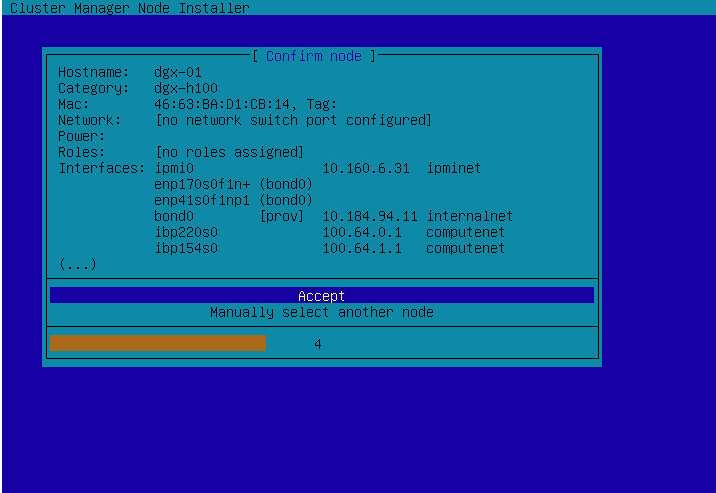
In the event that the DGX successfully identifies itself, you will see the following automated “Confirm node” prompt. The timer will expire and then proceed to provision the DGX with the displayed identity.
If required, validate the DGX hostname/category/MAC/network IPs with the site survey.
The next screen shows when a DGX appliance has successfully PXE booted.
This state is fully automated and no user intervention is required here.
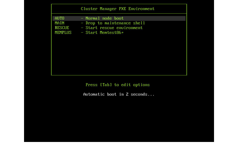
From here the DGX will proceed to provision itself via the served identity from the BCM headnode.
As the DGX progresses through the PXE boot provisioning process, you can monitor the progress from the headnode via cmsh.
Once DGX-01 successfully shows a status of UP we can proceed to clone this node identity for the remaining needed DGX’s, in this example we are adding 3 additional nodes for a total of 4.
[bcm10-headnode->device[dgx-01]]% ls
Type Hostname (key) MAC Category Ip Network Status
--------------------------------------------------------
HeadNode bcm10-headnode BC:00:00:00:43:45 10.133.11.51 managementnet [UP]
PhysicalNode dgx-01 94:00:00:00:91:FB dgx-h100 10.133.15.31 dgxnet [UP]
PhysicalNode node001 00:00:00:00:00:00 default 10.133.11.1 managementnet [ DOWN ]
[bcm10-headnode->device[dgx-01]]% foreach -o dgx-01 -n dgx-02..dgx-04 () --next-ip
[bcm10-headnode->device*]% commit
Successfully committed 3 Devices
Note
In the event the provisioning attempt fails or encounters problems refer to /var/log/messages and /var/log/node-installer log files to further diagnose the provisioning issue.
Set the MAC addresses for each of the new nodes. Repeat the steps below for each new DGX node, refer to the site survey for the details.
[bcm10-headnode->device]% use dgx-02; interfaces
[bcm10-headnode->device[dgx-02]->interfaces]% set enp170s0f1np1 mac 94:6D:00:00:00:FD
[bcm10-headnode->device*[dgx-02*]->interfaces*]% set enp41s0f1np1 mac 94:6D:00:00:00:FE
[bcm10-headnode->device*[dgx-02*]->interfaces*]% exit
[bcm10-headnode->device*[dgx-02*]]% set mac 94:6D:00:00:00:FD
[bcm10-headnode->device*[dgx-02*]]% commit
Proceed to power on and provision the remaining DGX nodes into the BCM Cluster.
You can verify the provisioning progress/status using cmsh
[bcm10-headnode1]% device;list
Type Hostname (key) MAC Category IP Network Status
--------------------------------------------------------
HeadNode bcm10-headnode1 84:16:0C:AD:DA:DE 10.184.94.254 managementnet [UP ], health check unknow+
PhysicalNode dgx-01 94:6D:AE:AA:13:C9 dgx-h100 10.184.94.11 managementnet [ UP ], health check failed+
PhysicalNode dgx-02 A0:88:C2:A3:44:E5 dgx-h100 10.184.94.12 managementnet [ UP ], health check unknown
PhysicalNode dgx-03 94:6D:AE:1C:80:CD dgx-h100 10.184.94.13 managementnet [INSTALLING] (provis+
PhysicalNode dgx-04 A0:88:C2:04:70:A1 dgx-h100 10.184.94.14 managementnet [ UP ], health check unknown