
NVIDIA DGX SuperPOD and BasePOD with DGX B300 Systems Deployment Guide with NVIDIA Mission Control#
Introduction#
This document provides the initial steps for deploying NVIDIA DGX SuperPOD and BasePOD with DGX B300 systems and NVIDIA Mission Control. Refer to the NMC Feature support matrix for supported features and functionality for B300 systems. - For NMC features, update and release notes, visit the NVIDIA Mission Control page.
After completing the B300 deployment prerequisites and control node configuration in this guide, continue with the NVIDIA Mission Control software installation guide to deploy NMC components.
Hardware Overview#
The following reference architectures detail the hardware and software requirements for the SuperPOD and BasePOD.
DGX B300 Ports and Connectivity Options#
This section describes DGX B300 system network ports and provides an overview of the networks used in this deployment.
Figure 3 shows the physical layout of the back of the DGX B300 system.
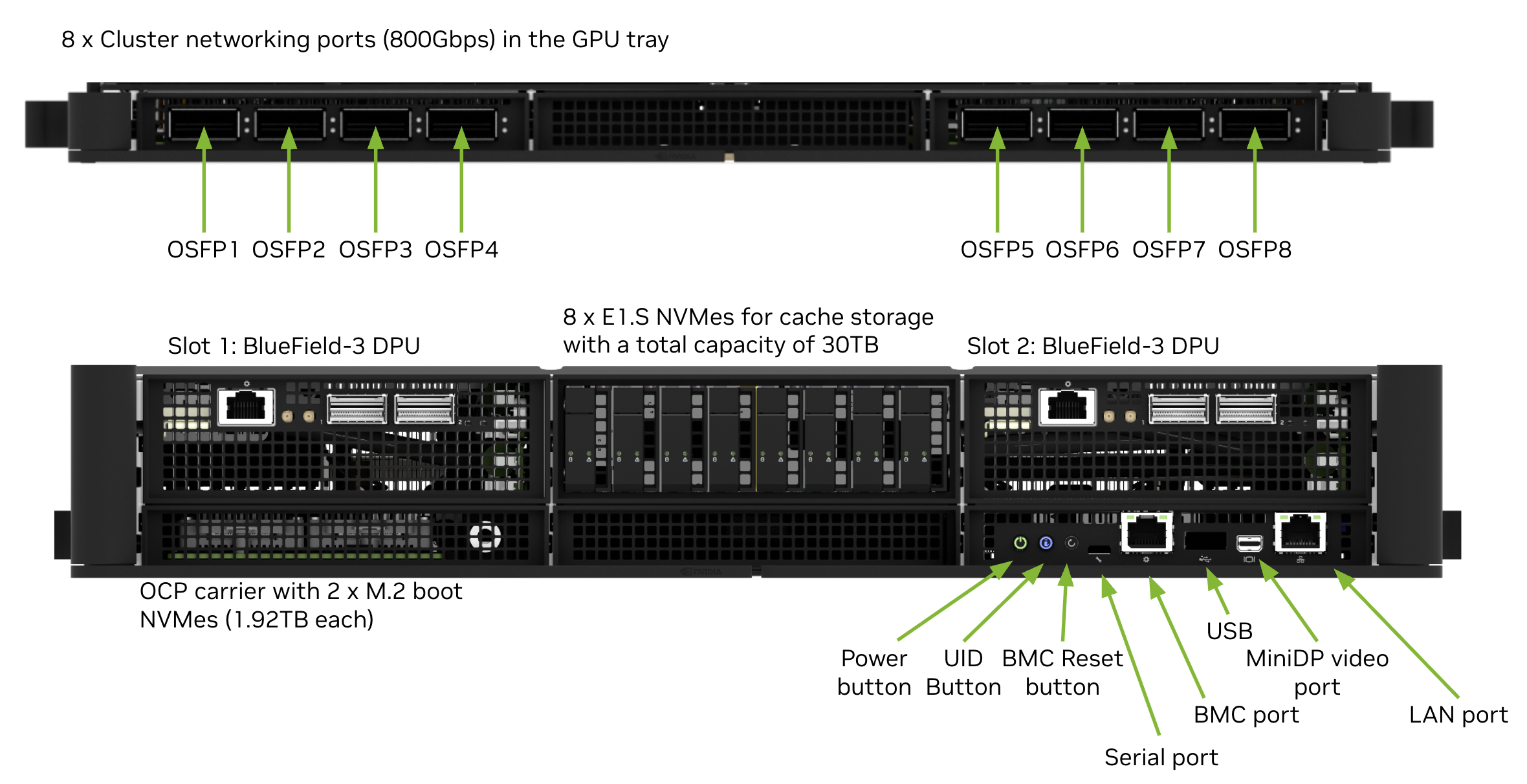
Figure 3 Physical layout of the back of the DGX B300 system#
Figure 4 shows how the DGX B300 network ports are used in this deployment guide.
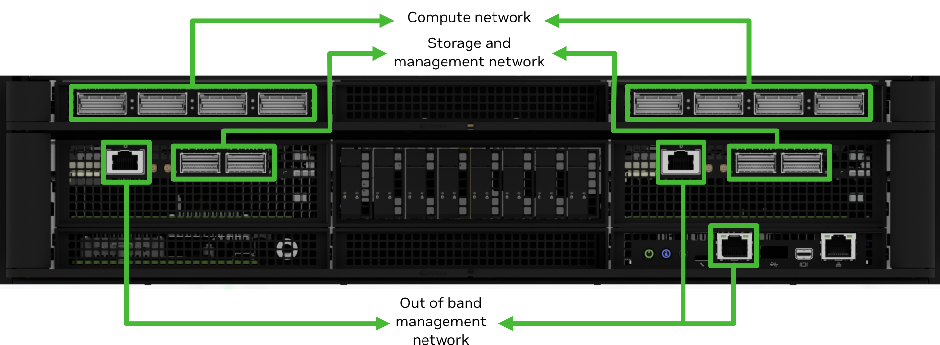
Figure 4 Physical layout of the back of the DGX B300 system#
DGX B300 network ports used in this deployment guide
The following ports are selected for DGX BasePOD networking:
Eight ports in four OSFP connections are used for the InfiniBand compute fabric
Each pair of dual-port NVIDIA BlueField-3 HCAs (NIC mode) provide parallel pathways to the storage and management fabrics.
Optionally, one port on a dual-port BlueField-3 HCA (IB mode) provides access to InfiniBand storage fabrics.
The B300 system BMC and the BMC ports of the two BlueField-3 DPUs are connected to the out-of-band management network.
The networking ports and their mapping are described in detail in the Network Ports section of the NVIDIA DGX B300 System User Guide.
Network Configuration#
Before installing Base Command Manager, configure the Ethernet management, out-of-band management, InfiniBand compute, and storage networks. See B300 Network Configuration for the network architecture, switch configuration examples, validation steps, and NVIDIA Air simulation resources.
Base Command Manager Headnodes Installation#
Download the Base Command Manager (BCM) ISO#
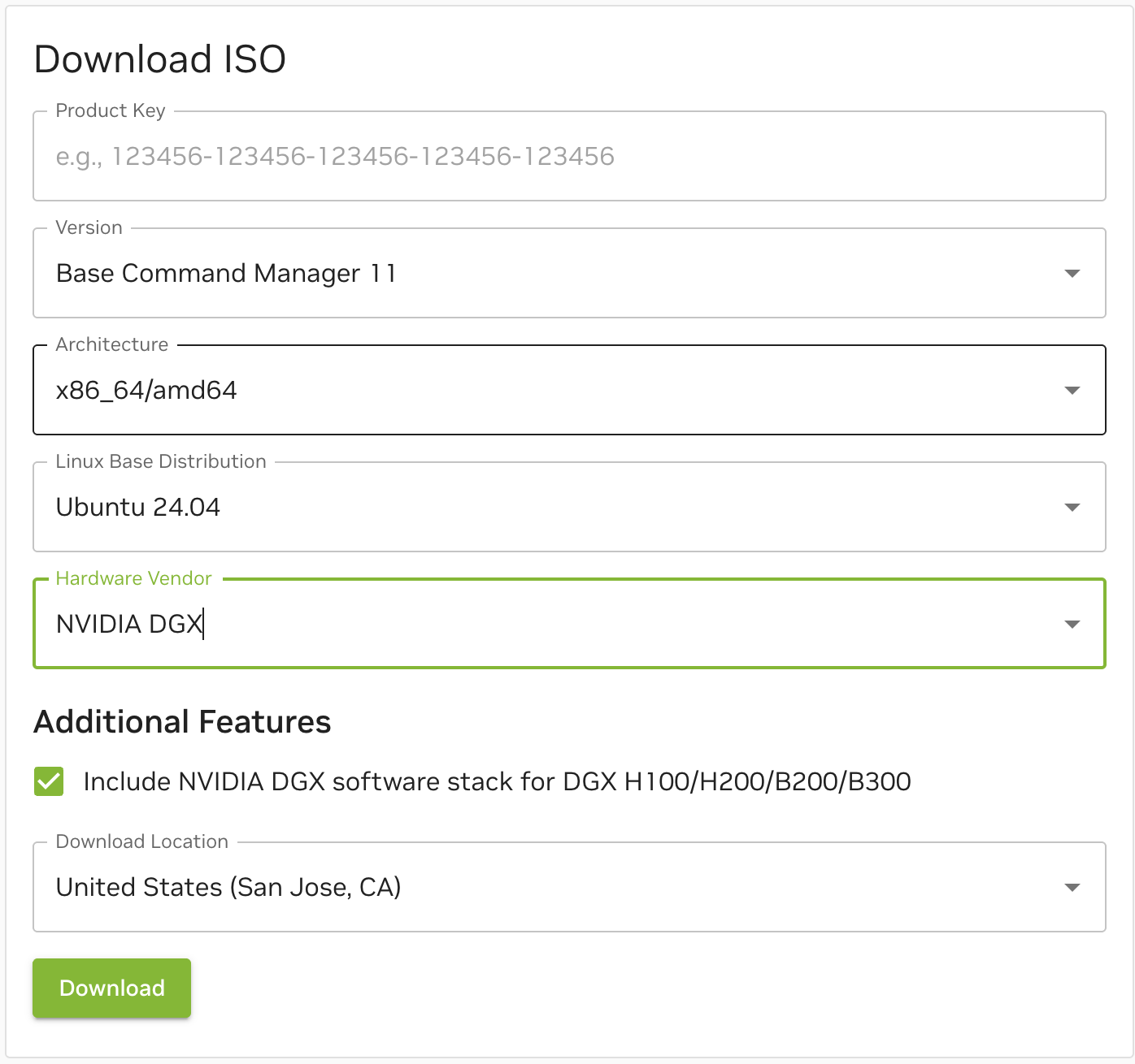
Download the latest BCM 11.x ISO image from the BCM website with the following options.
DGX B300 BIOS Configuration and Network Interface Boot Order#
The DGX B300 appliance BIOS typically ships from the factory configured to PXE boot using the two primary in-band interfaces. For detailed steps on modifying the boot order to utilize these interfaces for PXE booting, consult the DGX B300 System User Guide.
Control Nodes BIOS, OOB/BMC configuration#
Before installing BCM, configure the BIOS boot sequence and out-of-band management interface (such as BMC, IPMI) for all cluster nodes. Once configured, verify that all out-of-band management interfaces are reachable within the cluster network and that the BMC/iLO/iDRAC UI can be accessed.
On the control nodes, configure the interfaces connected to the management network to operate in Ethernet Mode (instead of IB). Additionally, enable PXE boot for all control nodes except the primary and secondary head nodes.
Example: Configuring BIOS and network interface boot order on a Dell appliance with iDRAC9#
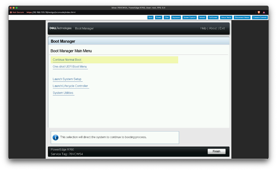
Power up the appliance and interrupt the boot cycle to enter the Boot Manager, then select “Launch System Setup”.
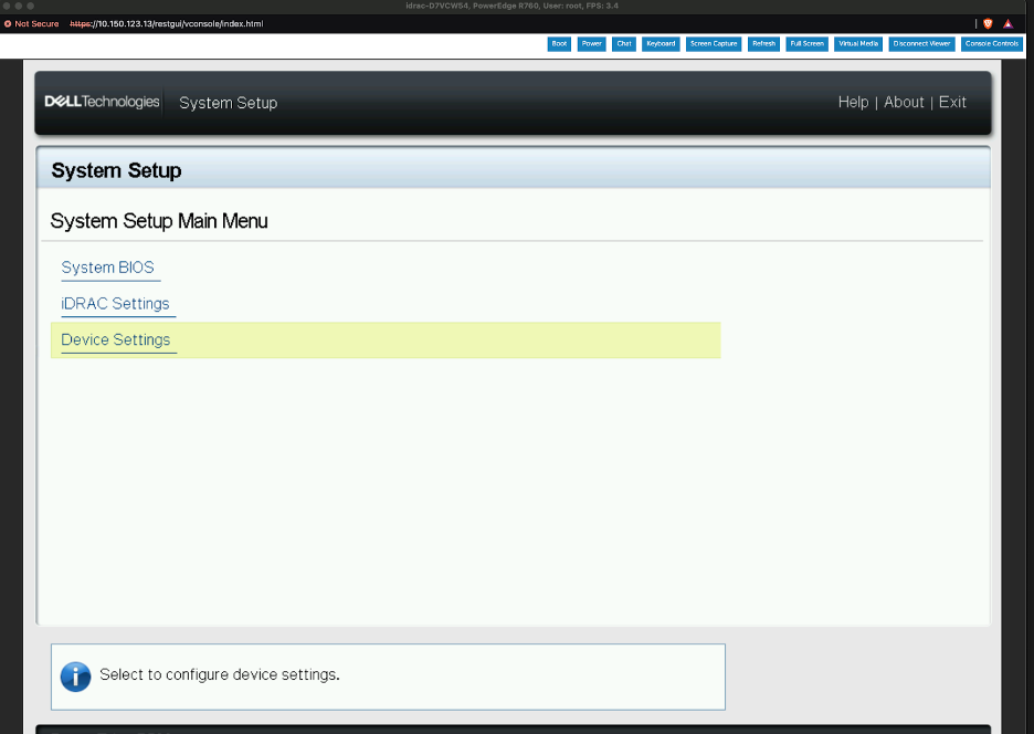
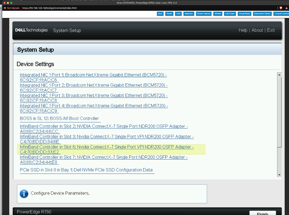
Select “Device Settings”.
Select the Card that needs the mode changed from Infiniband (IB Mode) to Ethernet (ETH Mode).
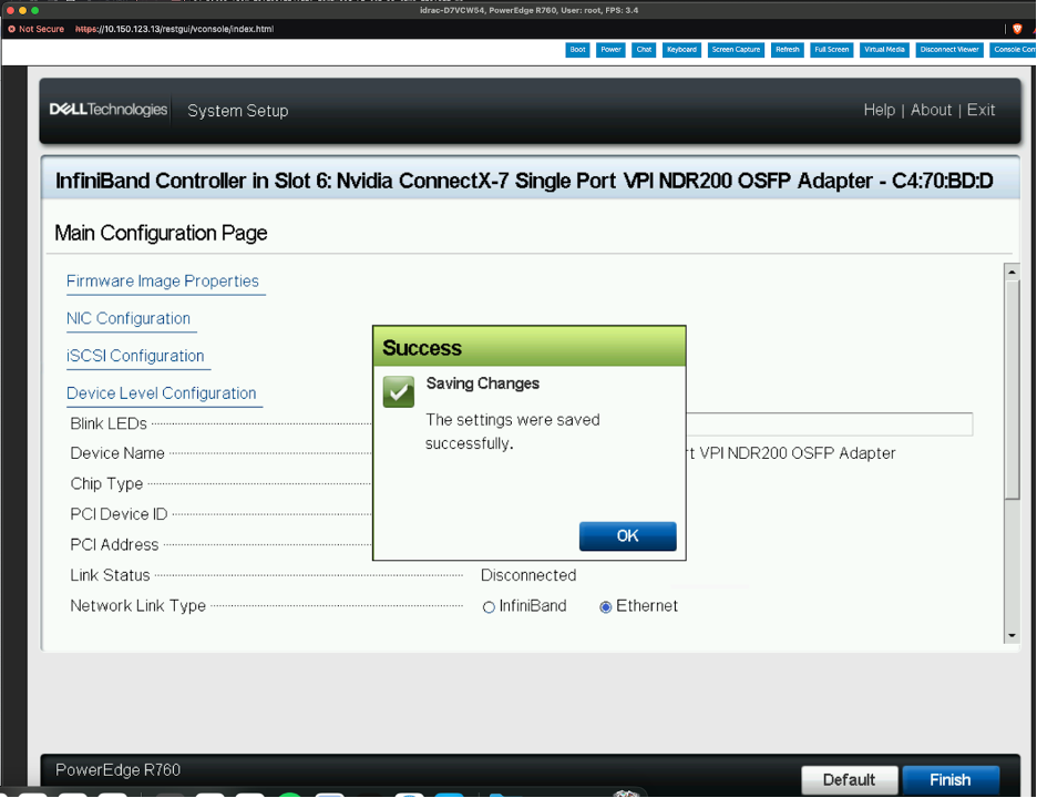
Change the “Network Link Type” from “Infiniband” to “Ethernet” and select “Finish”.
On the confirmation message, click OK.
After confirming the CX card ports are in the correct mode, proceed to enabling PXE boot.
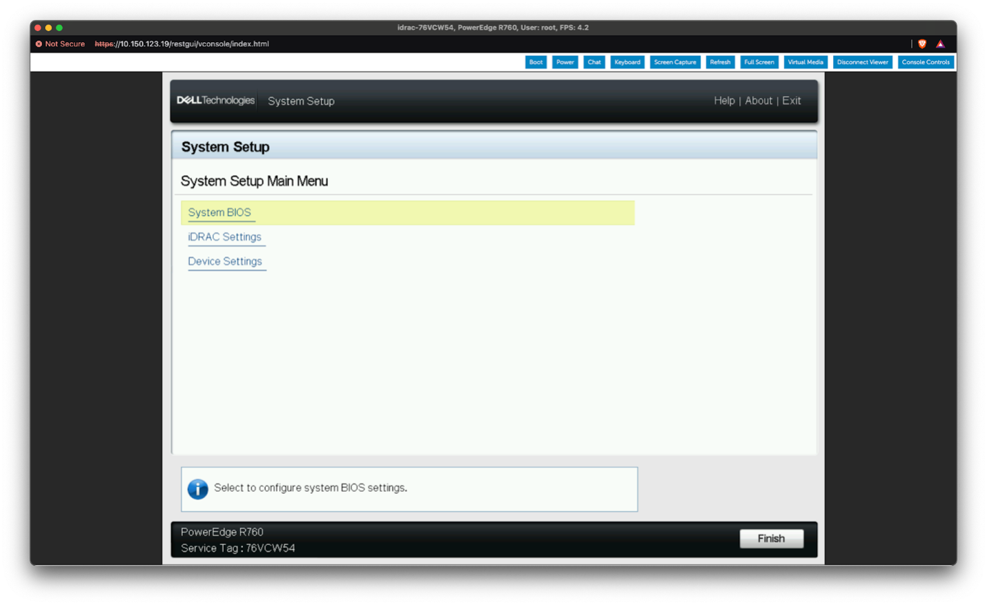
Return to the “System Setup” screen and select “System BIOS”.
Select “Network Settings”.
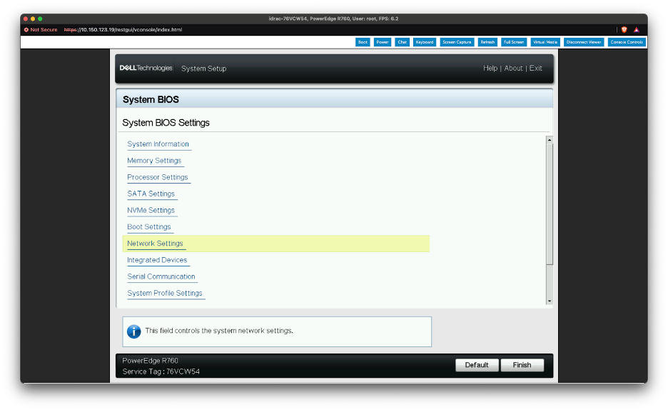
Enable PXE boot for the two primary in-band network interfaces.
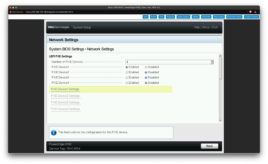
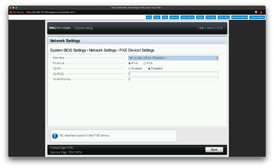
To confirm the changes, click “Back” to return to the “System BIOS” screen. A “Warning - Save Changes” prompt will appear; select “Yes.” Then, click “Finish” to go back to the System Setup Main Menu.
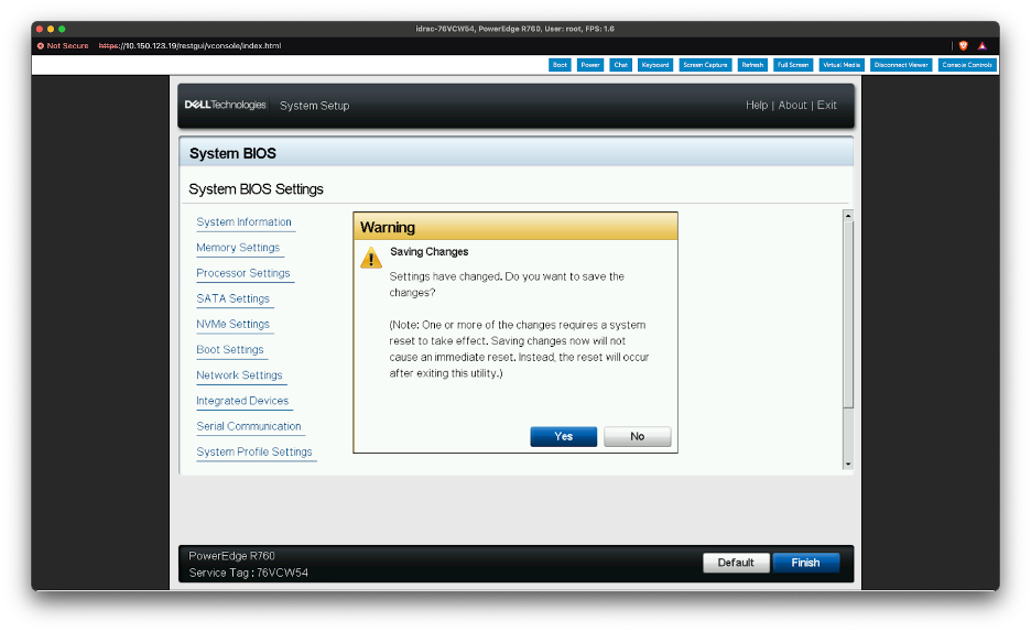
Select “Finish”, and on the “Warning - Confirm Exit” prompt select “Yes” to confirm the appliance reboot.
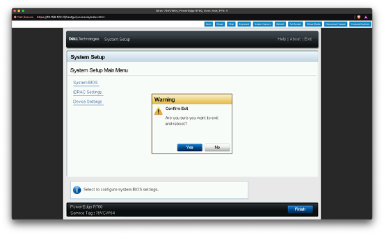
Ensure the PXE-enabled NICs are configured as the primary boot device.
Other Branded Appliances#
These settings are usually configured through the system’s BIOS or the appliance’s Out-of-Band management interface; refer to the vendor’s BMC/BIOS manual for specific instructions. Alternatively, you can adjust the port mode (Ethernet to IB) by temporarily booting the appliance into a Linux environment and utilizing the NVIDIA Firmware Tools.
Note
When using NVIDIA Firmware Tools, the device path in the example commands must be updated to reflect the correct PCIe address of the respective interface card. Do not execute the provided examples “as is” on a production system. Refer to the NVIDIA Firmware Tools documentation for detailed instructions on proper usage.
mstconfig -d 04:00.0 set LINK_TYPE_P1=2
RAID/Storage Configuration#
If available, configure the hardware RAID controller and disks to minimum RAID level 1 using the appliance’s BMC or BIOS. The procedure varies depending on the appliance vendor and RAID controller. Refer to the specific vendor documentation for the configuration procedure.
BCM Installation#
Headnode preparation#
Boot the headnode from the BCM installer ISO, which can be connected via USB, CD-ROM, or Virtual KVM. The specific steps for this process will differ based on the headnode appliance vendor.
Example BCM install with Dell appliances/iDRAC9#
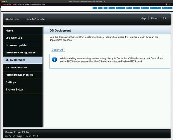
Boot the appliance into the Lifecycle Controller and select “OS Deployment” on the left side of the screen and then click “Deploy OS”.
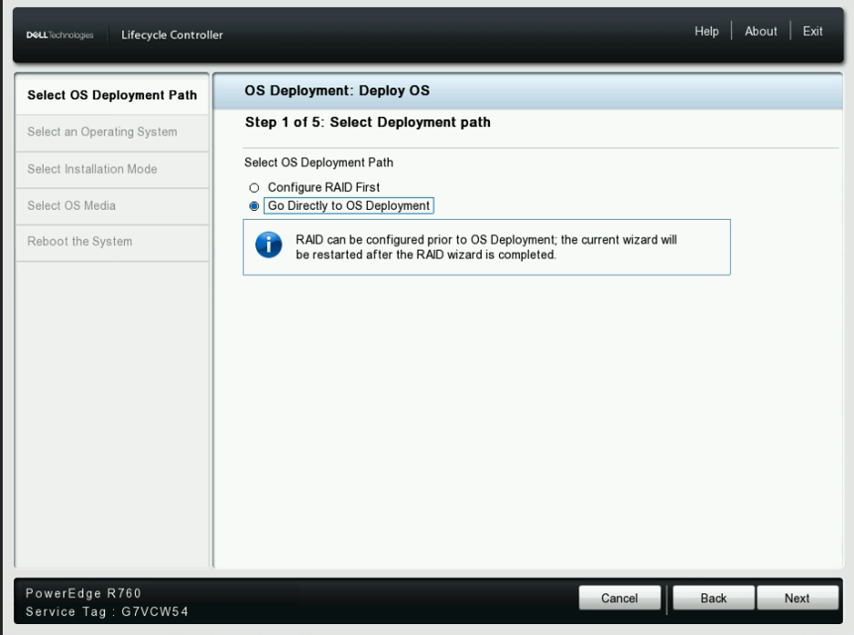
Select “Go Directly to OS Deployment” then click “Next”.
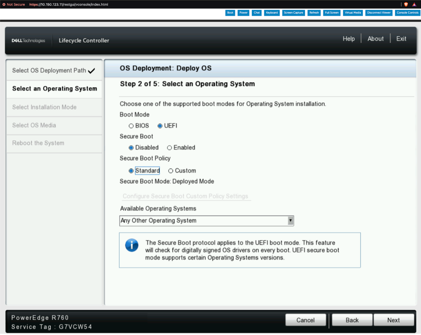
Set the Boot Mode to UEFI. Ensure Secure Boot is Disabled, the Secure Boot Policy is Standard, and “Any Other Operating System” is selected for the Available Operating System. Then, click “Next” to continue.
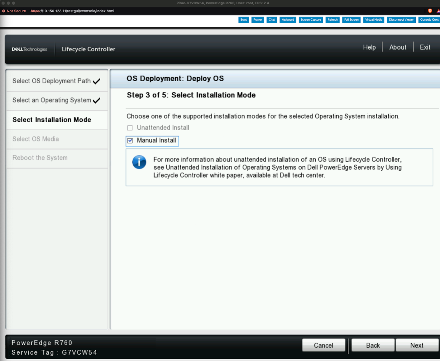
Select the option for “Manual Install” and click “Next”.
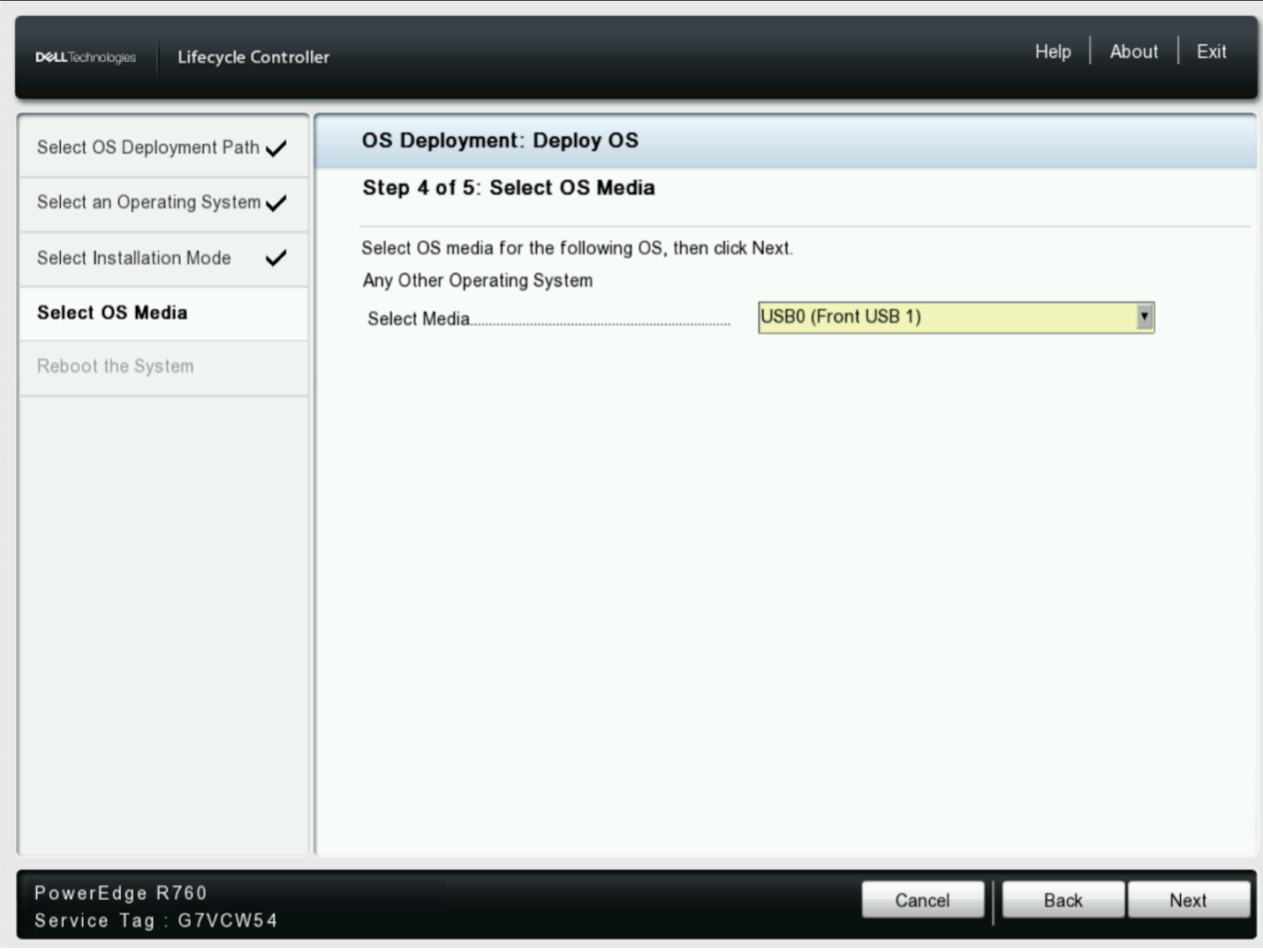
Proceed to choose the appropriate Media containing the BCM11 Installation ISO and then select “Next”.
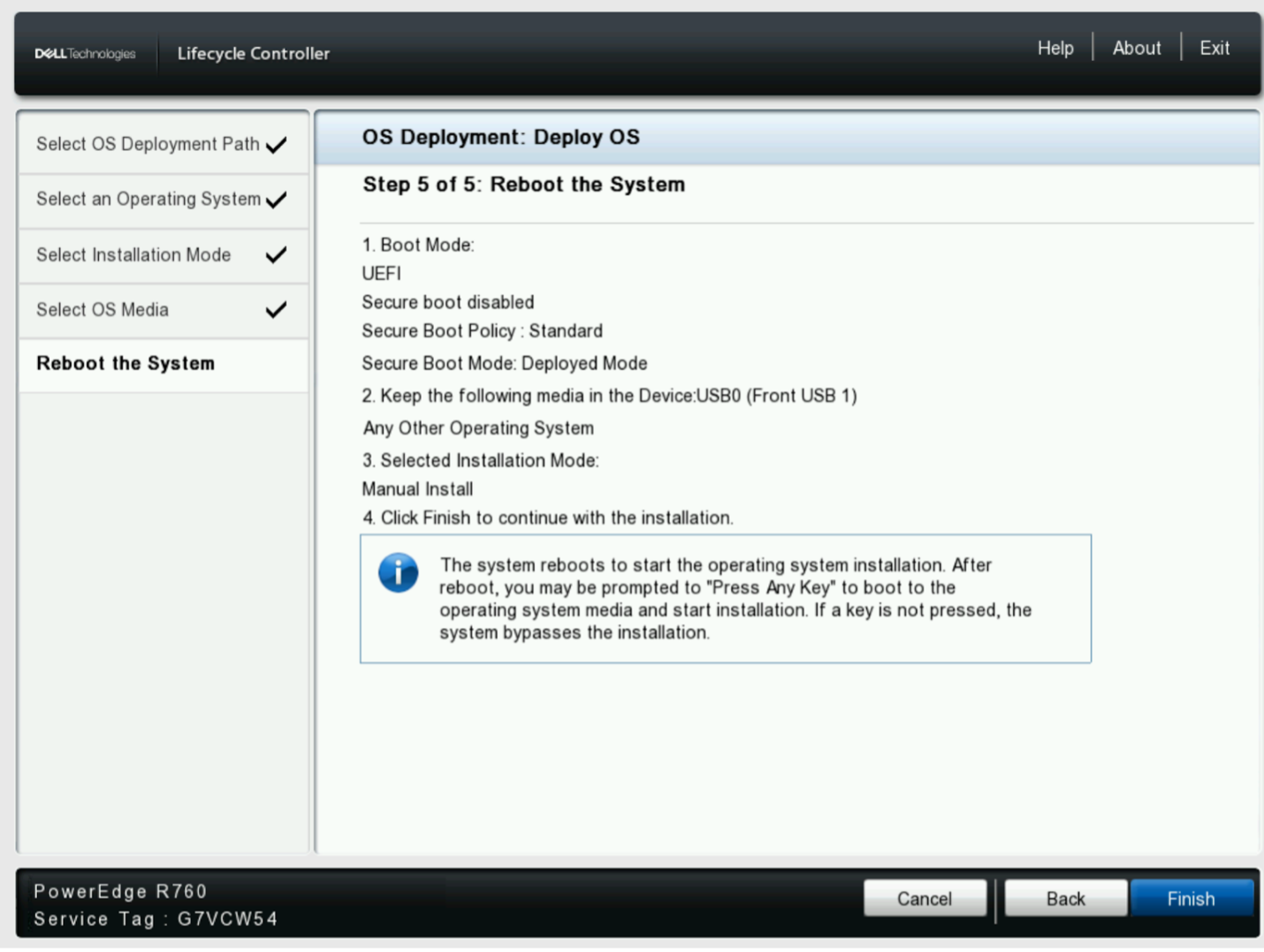
Confirm the selected options and select “Finish”.
The appliance will proceed to boot as normal.
Other Appliances#
Attach the BCM10 installation media to the designated headnode appliance. Power on the appliance and proceed to boot from the BCM10 installation media.
Booting the Base Command Manager Graphical Installer#
The BCM installer GUI will launch once the installation media has successfully loaded.
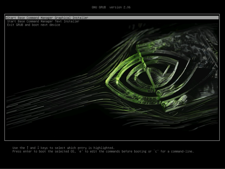
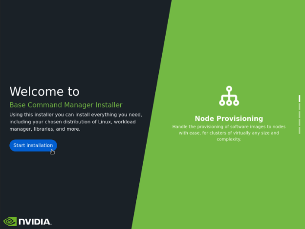
On the Base Command Manager Installer Splash Screen select “Start Installation”.
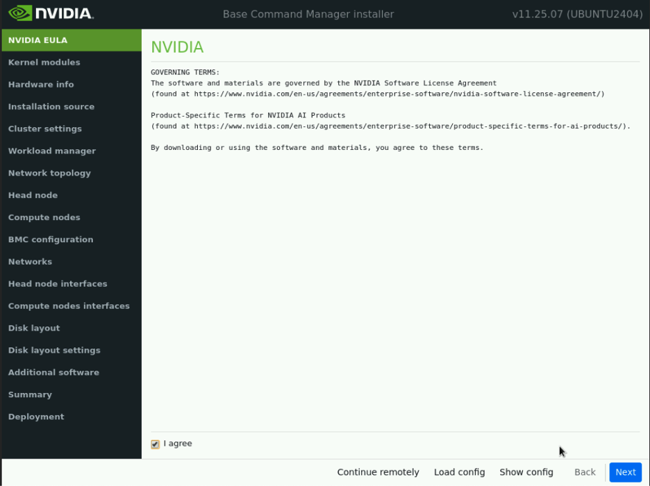
If you agree to the governing terms, select “I Agree” and then “Next.”
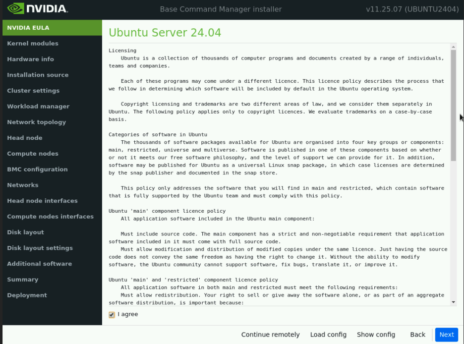
If you agree to the software licensing agreement, select “I Agree” and then “Next”.
On the “Kernel Modules” page select “Next”.
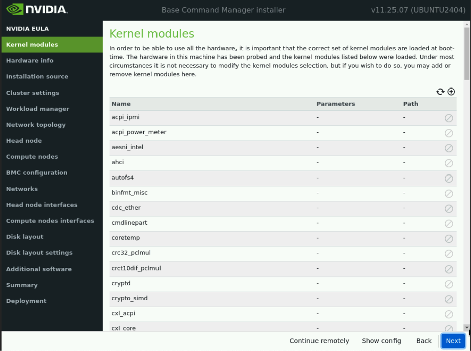
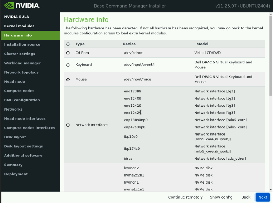
First, verify that the interface names for the two CX-7 OSFP interfaces (e.g., enp138s0np0 and enp47s0np0), configured in Ethernet Mode, match the site survey. These names are crucial for subsequent installation and Cluster Bring Up steps. Once documented, proceed by clicking “Next.”
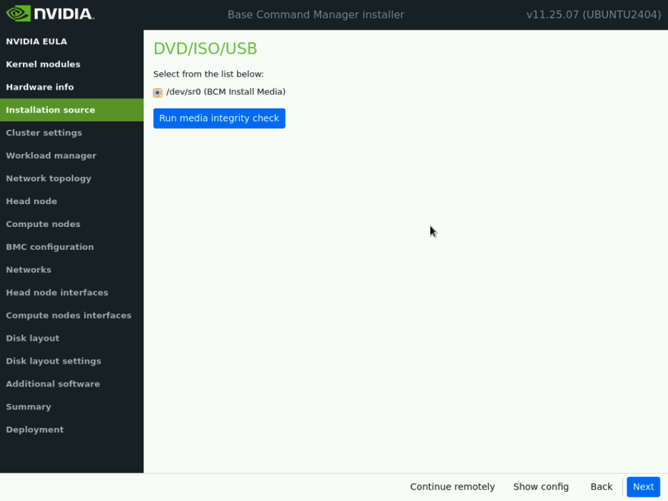
Select the appropriate install media source:
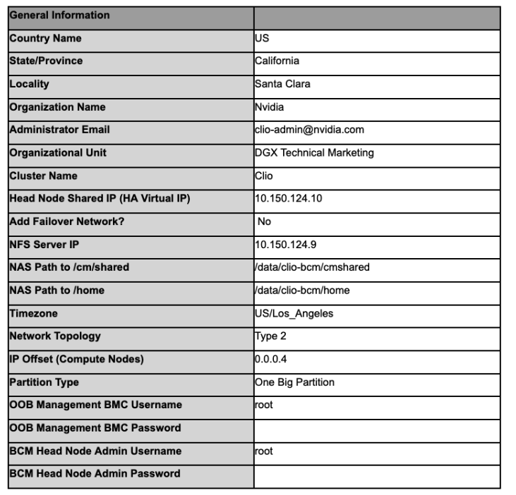
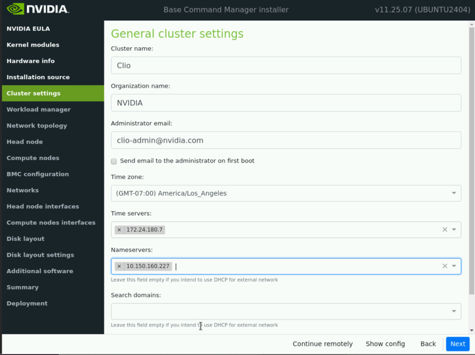
Populate the “Cluster settings” page with the requested details from the site survey.
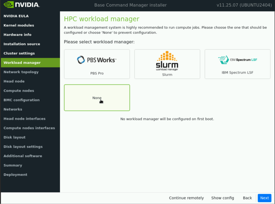
Select “None” as the HPC workload manager, then click “Next”.
Select “Type2” as the Network Topology, then click “Next”.
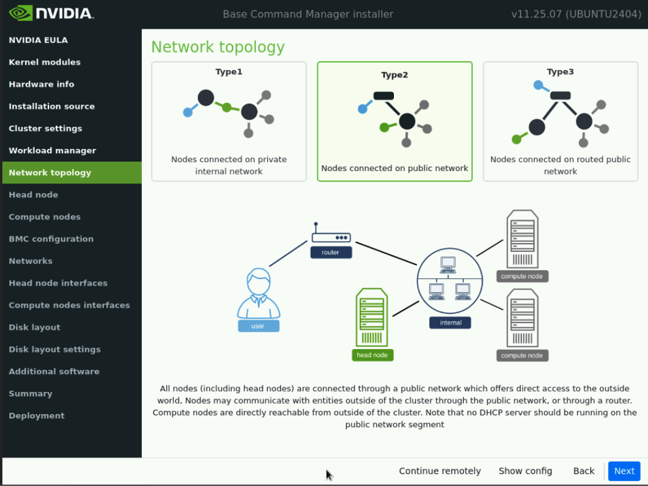
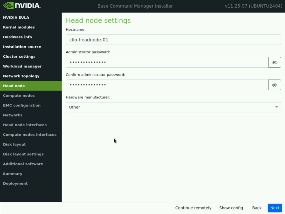
In this deployment example, a Type 2 network is used. More information on network types is available in the BCM Installation Manual. On the Head Node settings page, populate all requested values.
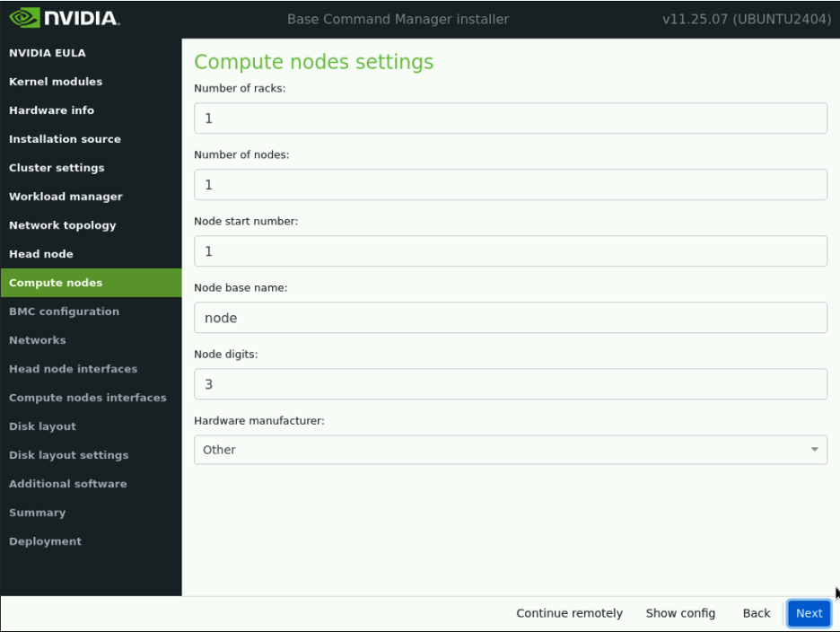
On the Compute Nodes page, accept the default values and click “Next.”
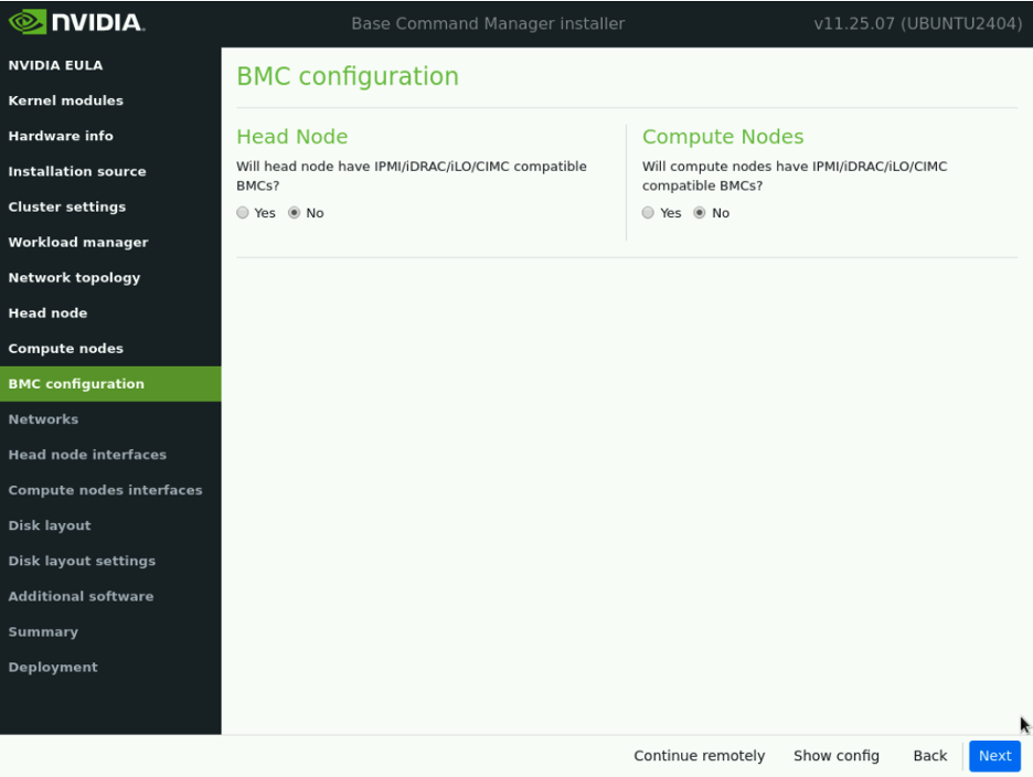
Under BMC configuration select “No” for both Head Node & Compute Nodes, then select “Next”.
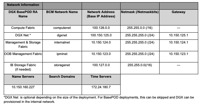
Proceed to populate the Networks page as per site survey.
Note
Only populate Internalnet, the other networks used in the DGX cluster will be defined during Cluster Bring Up.
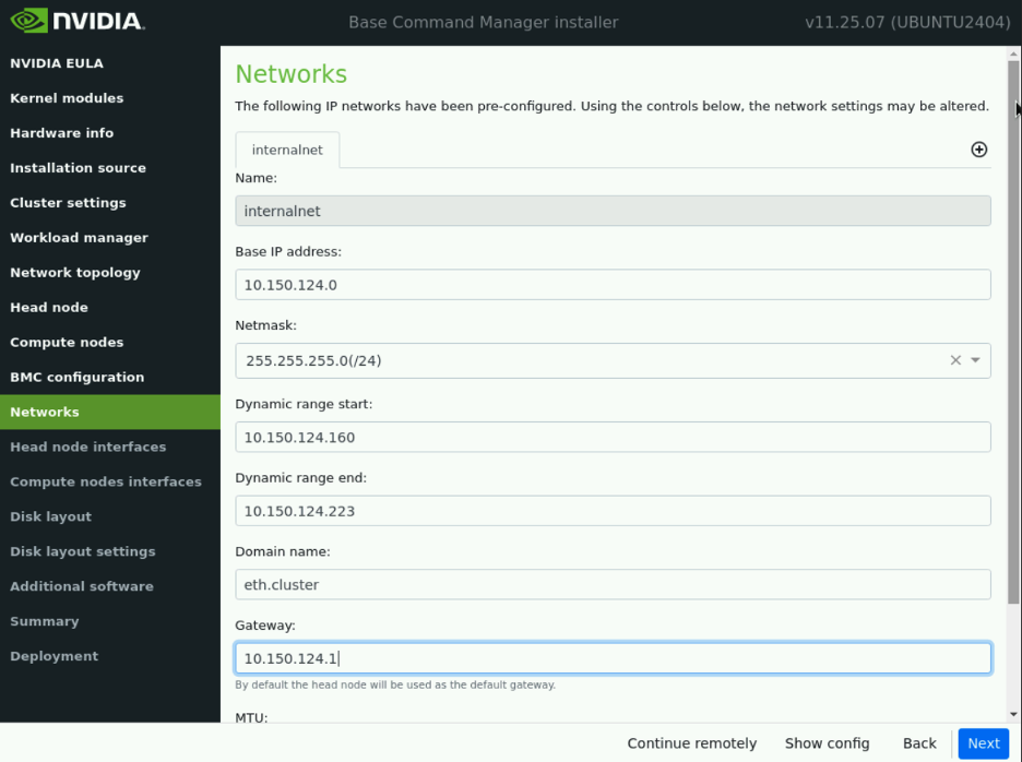
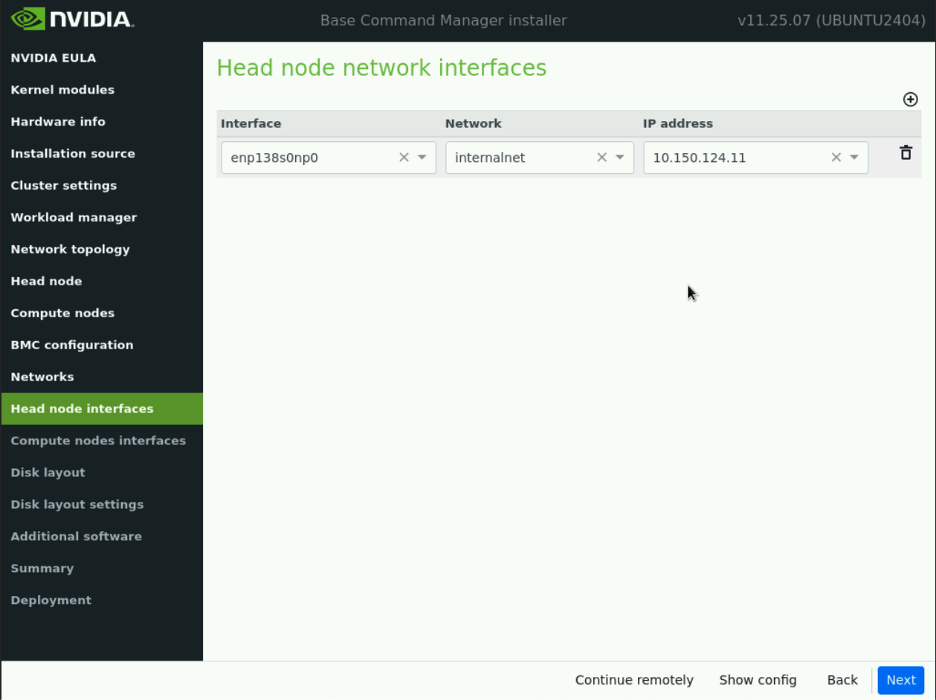
Next, populate the head node interface IP addresses.
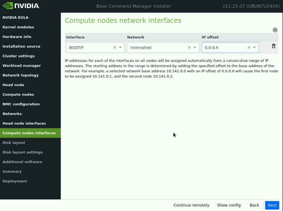
Set network offsets to 0.0.0.4 and select “Next”.
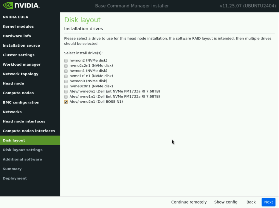
Choose the installation drive. It is recommended to install BCM on a RAID1 compliant drive. For Dell appliances, select the “Dell BOSS-N1” drive. In other cases where only software RAID is available, select a minimum of two drives, then click “Next”.
RAID controllers can be configured using the appliance’s BMC or vendor-provided software.
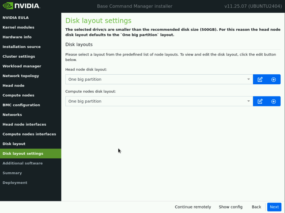
On the Disk Layout Settings page, select “One Big Partition” for both the head node and compute node disk layouts.
Leave CUDA unchecked.
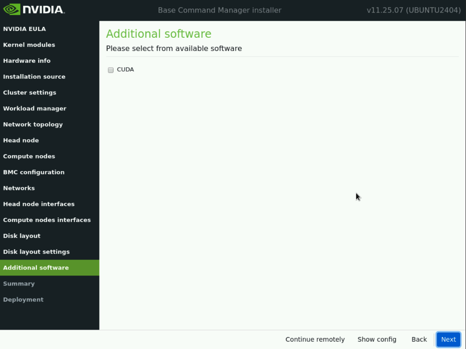
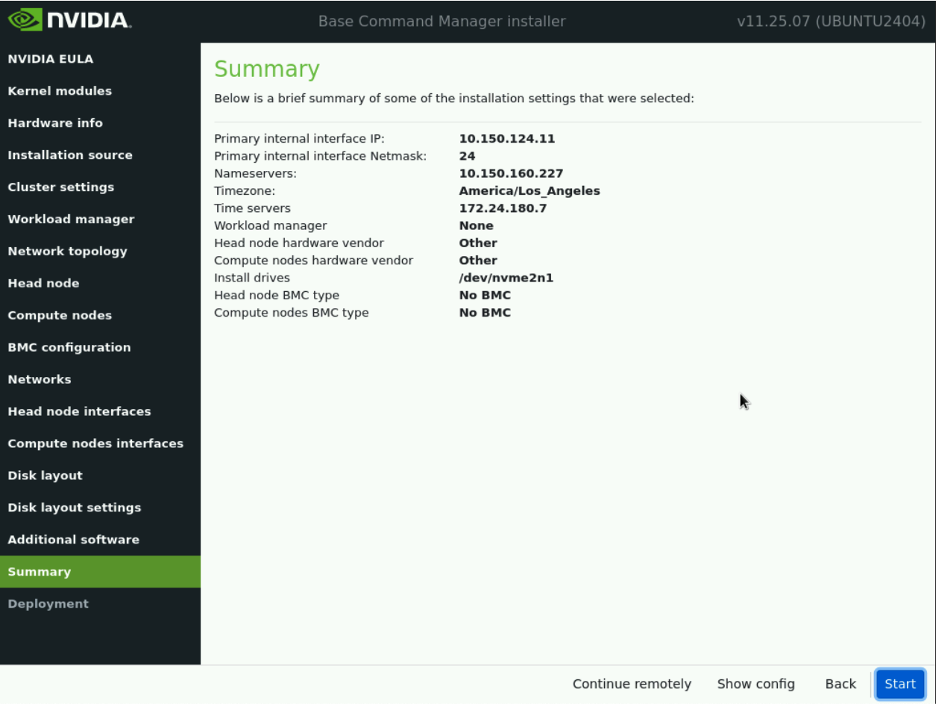
Do not select the CUDA option; this deployment uses the CUDA stack from the DGX OS image. Once you have reviewed the configuration, you can either select “Back” to make corrections on the association configuration page or click “Start” to proceed with the installation.
Monitor installation progress. Typical installation time is approximately 15-30 minutes.
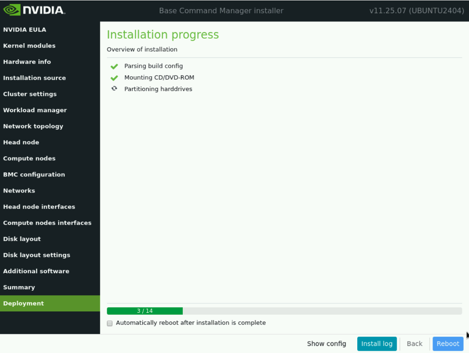
After a successful installation, the node briefly displays the following screen before automatically rebooting (if selected).
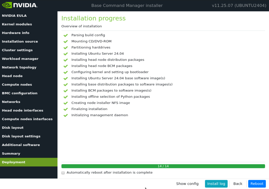
First time booting into BCM#
After the head node finishes rebooting from the installation environment, SSH to the head node. Proceed to update the headnode to the newest available packages.
root@clio-headnode-01:~# apt update && apt upgrade -y
Select Keep the local version in the following dialog box.
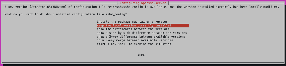
On successful update, reboot the head-node.
Activate the BCM Cluster License - Online#
SSH to headnode and activate the Cluster License with the request-license command
root@clio-headnode-01:~# request-license
Product Key (XXXXXX-XXXXXX-XXXXXX-XXXXXX-XXXXXX):000000-...-000000
Country Name (2 letter code): US
State or Province Name (full name): California
Locality Name (e.g. city): Santa Clara
Organization Name (e.g. company): NVIDIA
Organizational Unit Name (e.g. department): DGX Technical Marketing
Cluster Name: Clio
Private key data saved to /cm/local/apps/cmd/etc/cluster.key.new

Warning: Permanently added 'clio-headnode-01' (ED25519) to the list of known hosts.
MAC Address of primary head node (clio-headnode-01) for ens3f1np1 [08:C0:00:00:00:00]: 00:00:00:00:00:0F
Will this cluster use a high-availability setup with 2 head nodes? [y/N] y
MAC Address of secondary head node for eth0 [XX:XX:XX:XX:XX:XX]: 00:00:00:00:00:FF

Certificate request data saved to /cm/local/apps/cmd/etc/cluster.csr.new
Submit certificate request to http://licensing.brightcomputing.com/licensing/index.cgi ? [Y/n] Y

Contacting http://licensing.brightcomputing.com/licensing/index.cgi...

License granted.
License data was saved to /cm/local/apps/cmd/etc/cluster.pem.new
Install license? [Y/n] Y
========= Certificate Information ========
Version:                    10
Edition:                    Advanced
OEM:                        NVIDIA
Common name:                CLIO Cluster
Organization:               NVIDIA
Organizational unit:        DGX Technical Marketing
Locality:                   Santa Clara
State:                      California
Country:                    US
Serial:                     2981953
Starting date:              07/Apr/2024
Expiration date:            31/Mar/2030
MAC address / Cloud ID:     16:49:F4:74:C0:54|0E:54:0A:9F:3A:10
Licensed tokens:            512
Accounting & Reporting:     Yes
Allow edge sites:           Yes
License type:               Commercial
==========================================


Is the license information correct ? [Y/n] Y
Backup directory of old license: /var/spool/cmd/backup/certificates/2025-03-31_15.31.58
Installed new license
Revoke all existing cmd certificates

Waiting for CMDaemon to stop: OK

Installing admin certificates

Waiting for CMDaemon to start: OK
mysql: [Warning] Using a password on the command line interface can be insecure.
Copy cluster certificate to 3 images / node-installers
Copy cluster certificate to /cm/images/default-image//cm/local/apps/cmd/etc/cluster.pem
Copy cluster certificate to /cm/node-installer//cm/local/apps/cmd/etc/cluster.pem


Regenerating certificates for users
New license was installed. In order to allow compute nodes to obtain a new
node certificate, all compute nodes must be rebooted.

Please issue the following command to reboot all compute nodes:
    pdsh -g computenode reboot
Activate the BCM Cluster License - Offline/Airgapped installations#
Install the license using the following steps for air-gapped environments.
root@clio-headnode-01:~# request-license
Product Key (XXXXXX-XXXXXX-XXXXXX-XXXXXX-XXXXXX):000000-...-000000
Country Name (2 letter code): US
State or Province Name (full name): CA
Locality Name (e.g. city): Santa Clara
Organization Name (e.g. company): NVIDIA
Organizational Unit Name (e.g. department): NSV Mission Control
Cluster Name: Viking
Private key data saved to /cm/local/apps/cmd/etc/cluster.key.new

MAC Address of primary head node (clio-headnode-01) for ens1np0 [<MAC:MAC>]: <MAC:MAC>
Will this cluster use a high-availability setup with 2 head nodes? [y/N] y
MAC Address of secondary head node for eth0 [XX:XX:XX:XX:XX:XX]: <MAC:MAC>

Certificate request data saved to /cm/local/apps/cmd/etc/cluster.csr.new
Submit certificate request to http://licensing.brightcomputing.com/licensing/index.cgi ? [Y/n] N

Please use:
    http://licensing.brightcomputing.com/licensing/index.cgi
to obtain a license, or submit a support request through the Bright Computing website.

Contents of /cm/local/apps/cmd/etc/cluster.csr.new:

-----BEGIN CERTIFICATE REQUEST-----
…
…
…
-----END CERTIFICATE REQUEST-----
Go to the licensing portal to generate the license file using the CSR generated above.
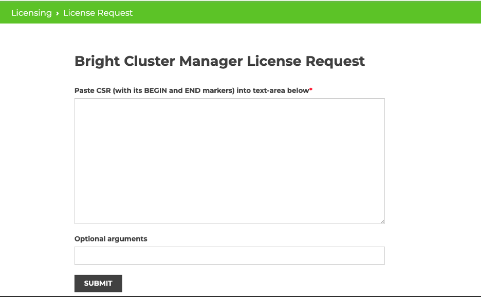
Install the license file by copying the contents of the generated license to a file and install it using install-license <file name> command
root@clio-headnode-01:~# vi license-file
# Paste the generated license contents #
root@clio-headnode-01:~#   install-license license-file
mysql: [Warning] Using a password on the command line interface can be insecure.
========= Certificate Information ========
Version:                    10
Edition:                    NVIDIA Mission Control
OEM:                        NVIDIA
Common name:                Viking
Organization:               NVIDIA
Organizational unit:        NSV Mission Control
Locality:                   Santa Clara
State:                      CA
Country:                    US
Serial:                     <>
Starting date:              08/Feb/2025
Expiration date:            23/Oct/2025
MAC address / Cloud ID:     88:E9:A4:20:18:9C|88:E9:A4:20:18:1C
Licensed tokens:            8192
Accounting & Reporting:     Yes
Allow edge sites:           Yes
License type:               Free
==========================================

Is the license information correct ? [Y/n] Y
Backup directory of old license: /var/spool/cmd/backup/certificates/2025-07-23_15.34.30
Installed new license
Revoke all existing cmd certificates

Waiting for CMDaemon to stop: OK

Installing admin certificates

Waiting for CMDaemon to start: OK
mysql: [Warning] Using a password on the command line interface can be insecure.
Copy cluster certificate to 3 images / node-installers
Copy cluster certificate to /cm/node-installer//cm/local/apps/cmd/etc/cluster.pem
Copy cluster certificate to /cm/images/dgx-image//cm/local/apps/cmd/etc/cluster.pem
Copy cluster certificate to /cm/images/default-image//cm/local/apps/cmd/etc/cluster.pem
mysql: [Warning] Using a password on the command line interface can be insecure.

Regenerating certificates for users

New license was installed. In order to allow compute nodes to obtain a new
node certificate, all compute nodes must be rebooted.

Please issue the following command to reboot all compute nodes:
        pdsh -g computenode reboot
Enable DeviceResolveAnyMAC#
The following section enables provisioning of the bonded interfaces on downstream appliances/nodes. This process enables failover PXE booting for bonded interfaces.
Edit /cm/local/apps/cmd/etc/cmd.conf and add the following line

AdvancedConfig = { "DeviceResolveAnyMAC=1" } # modified value
Example:

nano /cm/local/apps/cmd/etc/cmd.conf
GNU nano 6.2
# Set one or more advanced config parameters, only do this when needed
# AdvancedConfig = { "param=value", "param=value" }
AdvancedConfig = { "DeviceResolveAnyMAC=1" } # modified value
Once the above parameter has been saved restart the CMDaemon

root@bcm10-headnode:~# systemctl restart cmd
BCM Networking Configuration#
BCM networking configuration can be fully automated or manually configured. Refer to the following sections for more information.
Define Cluster Networks - Automated#
BCM can automate network switch provisioning and fabric configuration using bcm-netautogen. For automated large-scale deployments, contact your NVIDIA PTAM for NVIS engagement and assistance. The following sections outline the manual configuration steps.
Define Cluster Networks - Manual#
Nodes and networks can be manually defined within the BCM cluster using the steps outlined below.
Login to cmsh and define additional networks.
root@clio-headnode-01:~# cmsh
[clio-headnode-01]% network
[clio-headnode-01->network]% ls
Name (key)      Type            Netmask bits   Base address     Domain name             IPv6
------------------ -------------- -------------- ---------------- -------------------- ----
globalnet       Global          0               0.0.0.0         cm.cluster
internalnet     Internal        24              10.150.124.0    eth.cluster
Add ipminet. This is the out-of-band (OOB) management network.
[clio-headnode-01->network]% add ipminet
[clio-headnode-01->network*[ipminet*]]% set netmaskbits 24
[clio-headnode-01->network*[ipminet*]]% set baseaddress 10.150.123.0
[clio-headnode-01->network*[ipminet*]]% set excludefromsearchdomain yes
[clio-headnode-01->network*[ipminet*]]% set disableautomaticexports yes
[clio-headnode-01->network*[ipminet*]]% set gateway 10.150.123.1
[clio-headnode-01->network*[ipminet*]]% commit
Check that all the network settings are correct by running the show command for each network configured.
[clio-headnode-01->network[ipminet]]% show
Parameter                       Value
-------------------------------- ------------------------------------------------
Name                            ipminet
Private Cloud
Revision
Domain Name
Type                            Internal
MTU                             1500
Allow autosign                  Automatic
Write DNS zone                  both
Node booting                    no
Lock down dhcpd                 yes
Management allowed              yes
Search domain index             0
Exclude from search domain      yes
Disable automatic exports       yes
Base address                    10.150.123.0
Broadcast address               10.150.123.255
Dynamic range start             0.0.0.0
Dynamic range end               0.0.0.0
Netmask bits                    24
Gateway                         10.150.123.1
Cloud Subnet ID
EC2AvailabilityZone
Notes                           <0B>
Optional: create dgxnet(s) by cloning internalnet. For scaled deployments, multiple dgxnets can be used to isolate DGX nodes from the control nodes’ default management network. For small-scale deployments, DGX nodes can be provisioned in internalnet.
Note
Ensure the network is configured to forward DHCP requests from dgxnet to the BCM headnode IP.
[clio-headnode-01->network[ipminet]]% clone internalnet dgxnet
[clio-headnode-01->network*[dgxnet*]]% set domainname cm.dgx
[clio-headnode-01->network*[dgxnet*]]% set baseaddress 10.150.125.0
[clio-headnode-01->network*[dgxnet*]]% set gateway 10.150.125.1
[clio-headnode-01->network*[dgxnet*]]% commit
[clio-headnode-01->network[dgxnet]]% show
Parameter                       Value
-------------------------------- ------------------------------------------------
Name                            dgxnet
Private Cloud
Revision
Domain Name                     cm.dgx
Type                            Internal
MTU                             1500
Allow autosign                  Automatic
Write DNS zone                  both
Node booting                    yes
Lock down dhcpd                 no
Management allowed              yes
Search domain index             0
Exclude from search domain      no
Disable automatic exports       no
Base address                    10.150.125.0
Broadcast address               10.150.125.255
Dynamic range start             10.150.125.160
Dynamic range end               10.150.125.223
Netmask bits                    24
Gateway                         10.150.125.1
Cloud Subnet ID
EC2AvailabilityZone
Notes                           <0B>
Add computenet
[clio-headnode-01->network[dgxnet]]% add computenet
[clio-headnode-01->network*[computenet*]]% set domainname ib.compute
[clio-headnode-01->network*[computenet*]]% set baseaddress 100.126.0.0
[clio-headnode-01->network*[computenet*]]% set mtu 4000
[clio-headnode-01->network*[computenet*]]% commit
[clio-headnode-01->network[computenet]]% show
Parameter                           Value
-------------------------------- ------------------------------------------------
Name                                computenet
Private Cloud
Revision
Domain Name                         ib.compute
Type                                Internal
MTU                                 4000
Allow autosign                      Automatic
Write DNS zone                      both
Node booting                        no
Lock down dhcpd                     no
Management allowed                  no
Search domain index                 0
Exclude from search domain          no
Disable automatic exports           no
Base address                        100.126.0.0
Broadcast address                   100.126.255.255
Dynamic range start                 0.0.0.0
Dynamic range end                   0.0.0.0
Netmask bits                        16
Gateway                             0.0.0.0
Cloud Subnet ID
EC2AvailabilityZone
Notes                               <0B>
Add storagenet
[clio-headnode-01->network[computenet]]% clone computenet storagenet
[clio-headnode-01->network*[storagenet*]]% set domainname ib.storage
[clio-headnode-01->network*[storagenet*]]% set baseaddress 100.127.0.0
[clio-headnode-01->network*[storagenet*]]% commit
[clio-headnode-01->network[storagenet]]% show
Parameter                       Value
-------------------------------- ------------------------------------------------
Name                            storagenet
Private Cloud
Revision
Domain Name                     ib.storage
Type                            Internal
MTU                             4000
Allow autosign                  Automatic
Write DNS zone                  both
Node booting                    no
Lock down dhcpd                 no
Management allowed              no
Search domain index             0
Exclude from search domain      no
Disable automatic exports       no
Base address                    100.127.0.0
Broadcast address               100.127.255.255
Dynamic range start             0.0.0.0
Dynamic range end               0.0.0.0
Netmask bits                    16
Gateway                         0.0.0.0
Cloud Subnet ID
EC2AvailabilityZone
Notes                           <0B>
Before moving forward, verify the defined networks.
[clio-headnode-01->network[storagenet]]% ..
[clio-headnode-01->network]% ls
Name (key)      Type            Netmask bits   Base address     Domain name             IPv6
------------------ -------------- -------------- ---------------- -------------------- ----
computenet      Internal        16              100.126.0.0     ib.compute
dgxnet          Internal        24              10.150.125.0    cm.dgx
globalnet       Global          0               0.0.0.0         cm.cluster
internalnet     Internal        24              10.150.124.0    eth.cluster
ipminet         Internal        24              10.150.123.0
storagenet      Internal        16              100.127.0.0     ib.storage
Enable Bonding on the Headnode#
Note
Always use a remote or physical KVM for this action, not SSH. Before you begin, confirm that the headnode’s out-of-band management, BMC interface, or remote/physical KVM is reachable and working.
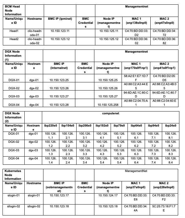
In this step, clear the interface IP assigned to the primary interface during installation, then assign that IP to the newly created bonded interface. Refer to the site survey for the network interface names and MAC addresses.
Login to headnode and run Cluster Manager Shell (cmsh).
root@clio-headnode-01:~# cmsh
[clio-headnode-01]% device
[clio-headnode-01->device]% use clio-headnode-01
[clio-headnode-01->device[clio-headnode-01]]% interfaces
[clio-headnode-01->device[clio-headnode-01]->interfaces]% ls
Type            Network device name  IP                 Network         Start if
------------ -------------------- ---------------- ---------------- --------
physical        enp138s0np0 [prov]   10.150.124.12      internalnet     always
[clio-headnode-01->device[clio-headnode-01]->interfaces]% add bmc ipmi0 10.150.123.11 ipminet
[clio-headnode-01->device*[clio-headnode-01*]->interfaces*[enpenp138s0np0*]]% add physical enp47s0np0
[clio-headnode-01->device*[clio-headnode-01*]->interfaces*[enp47s0np0*]]% add bond bond0 10.150.124.12 internalnet
[clio-headnode-01->device*[clio-headnode-01*]->interfaces*[bond0*]]% set mode 4
[clio-headnode-01->device*[clio-headnode-01*]->interfaces*[bond0*]]% set interfaces enp138s0np0 enp47s0np0
[clio-headnode-01->device*[clio-headnode-01*]->interfaces*[bond0*]]% use enp138s0np0
[clio-headnode-01->device*[clio-headnode-01*]->interfaces*[enp138s0np0]]% clear network
[clio-headnode-01->device*[clio-headnode-01*]->interfaces*[enp138s0np0*]]% clear ip
[clio-headnode-01->device*[clio-headnode-01*]->interfaces*[enp138s0np0*]]% ..
[clio-headnode-01->device*[clio-headnode-01*]->interfaces*]% ..
[clio-headnode-01->device*[clio-headnode-01*]]% set provisioninginterface bond0
[clio-headnode-01->device*[clio-headnode-01*]]% commit
[clio-headnode-01->device[clio-headnode-01]->interfaces]% ls
Type         Network device name  IP               Network          Start if
------------ -------------------- ---------------- ---------------- --------
bmc          ipmi0                10.150.123.12    ipminet          always
bond         bond0 [prov]         10.150.124.12    internalnet      always
physical     enp138s0np0 (bond0)  0.0.0.0                           always
physical     enp47s0np0 (bond0)   0.0.0.0                           always
[clio-headnode-01->device[clio-headnode-01]->interfaces]% use bond0
[clio-headnode-01->device[clio-headnode-01]->interfaces[bond0]]% show
Parameter                        Value
-------------------------------- ------------------------------------------------
Revision
Type                             bond
Network device name              bond0 [prov]
Network                          internalnet
IP                               10.150.124.12
DHCP                             no
Alternative Hostname
Additional Hostnames
Switch ports
Start if                         always
BringUpDuringInstall             no
On network priority              70
Mode                             4 (802.3ad)
Options
Interfaces                       enp138s0np0,enp47s0np0
Verify the IP connectivity to the BCM headnode using ping/ssh before proceeding.
Should the head node’s network connection fail to update after committing changes, access the appliance console via BMC or physical KVM and restart the networking service to apply the changes.
[clio-headnode-01->device[clio-headnode-01]->interfaces]% !systemctl restart networking.service

or
root@clio-headnode-01:~# systemctl restart networking.service
Add fsexports for Additional networks (e.g dgxnet) in BCM#
This step applies only if DGX nodes use a separate network; otherwise, it is not applicable. If multiple DGXnets are in use, repeat these steps for each network where nodes are provisioned.
Enable shared filesystem access from additional networks to facilitate appliance provisioning.
root@clio-headnode-01:~# cmsh
[clio-headnode-01]% device
[clio-headnode-01->device]% use clio-headnode-01
[clio-headnode-01->device[clio-headnode-01]]% fsexports
[clio-headnode-01->device[clio-headnode-01]->fsexports]% ls
Name (key)                                   Path                             Network                  Hosts        Write  Disabled
-------------------------------------------- -------------------------------- ------------------------ ------------ ------ --------
/cm/node-installer@internalnet               /cm/node-installer               internalnet                           no     no
/cm/node-installer/certificates@internalnet  /cm/node-installer/certificates  internalnet                           yes    no
/var/spool/burn@internalnet                  /var/spool/burn                  internalnet                           yes    no
/home@internalnet                            /home                            internalnet                           yes    no
/cm/shared@internalnet                       /cm/shared                       internalnet                           yes    no
[clio-headnode-01->device[clio-headnode-01]->fsexports]% add /cm/node-installer dgxnet
[clio-headnode-01->device*[clio-headnode-01*]->fsexports*[/cm/node-installer@dgxnet*]]% ..
[clio-headnode-01->device*[clio-headnode-01*]->fsexports*]% add /cm/node-installer/certificates dgxnet
[clio-headnode-01->device*[clio-headnode-01*]->fsexports*[/cm/node-installer/certificates@dgxnet*]]% set write yes
[clio-headnode-01->device*[clio-headnode-01*]->fsexports*[/cm/node-installer/certificates@dgxnet*]]% ..
[clio-headnode-01->device*[clio-headnode-01*]->fsexports*]% add /var/spool/burn dgxnet
[clio-headnode-01->device*[clio-headnode-01*]->fsexports*[/var/spool/burn@dgxnet*]]% set write yes
[clio-headnode-01->device*[clio-headnode-01*]->fsexports*[/var/spool/burn@dgxnet*]]% ..
[clio-headnode-01->device*[clio-headnode-01*]->fsexports*]% add /home dgxnet
[clio-headnode-01->device*[clio-headnode-01*]->fsexports*[/home@dgxnet*]]% set write yes
[clio-headnode-01->device*[clio-headnode-01*]->fsexports*[/home@dgxnet*]]% ..
[clio-headnode-01->device*[clio-headnode-01*]->fsexports*]% add /cm/shared dgxnet
[clio-headnode-01->device*[clio-headnode-01*]->fsexports*[/cm/shared@dgxnet*]]% set write yes
[clio-headnode-01->device*[clio-headnode-01*]->fsexports*[/cm/shared@dgxnet*]]% ..
[clio-headnode-01->device*[clio-headnode-01*]->fsexports*]% ls
Name (key)                                   Path                             Network                  Hosts        Write  Disabled
-------------------------------------------- -------------------------------- ------------------------ ------------ ------ --------
/cm/node-installer@internalnet               /cm/node-installer               internalnet                           no     no
/cm/node-installer/certificates@internalnet  /cm/node-installer/certificates  internalnet                           yes    no
/var/spool/burn@internalnet                  /var/spool/burn                  internalnet                           yes    no
/home@internalnet                            /home                            internalnet                           yes    no
/cm/shared@internalnet                       /cm/shared                       internalnet                           yes    no
/cm/node-installer@dgxnet                    /cm/node-installer               dgxnet                                no     no
/cm/node-installer/certificates@dgxnet       /cm/node-installer/certificates  dgxnet                                yes    no
/var/spool/burn@dgxnet                       /var/spool/burn                  dgxnet                                yes    no
/home@dgxnet                                 /home                            dgxnet                                yes    no
/cm/shared@dgxnet                            /cm/shared                       dgxnet                                yes    no
[clio-headnode-01->device*[clio-headnode-01*]->fsexports*]% commit
[clio-headnode-01->device[clio-headnode-01]->fsexports]%
Fri Jan 17 18:05:16 2025 [notice] clio-headnode-01: Service nfs was reloaded
[clio-headnode-01->device[clio-headnode-01]->fsexports]%
Node Provisioning#
The configuration of the control and DGX nodes can be performed either manually or automatically, depending on the deployment’s scale.
The following sections outline the manual node provisioning steps.
Manual Provisioning - Create Control Node Definitions#
Note
In this example, we are defining Slurm Node, slogin-01. Repeat the same procedure for other control nodes like kubernetes/Run:AI
Clone the default image.
[clio-headnode-01->softwareimage]% clone default-image slogin-image
[clio-headnode-01->softwareimage*[slogin-image*]]% commit
Clone default category to create the slogin category and set the software image to slogin-image.
[clio-headnode-01->category]% clone default slogin
[clio-headnode-01->category*[slogin*]]% set softwareimage slogin-image
[clio-headnode-01->category*[slogin*]]% commit
Add a new physical node for the slogin-01 node and set its IP address.
[clio-headnode-01]% device
[clio-headnode-01->device]% add physicalnode slogin-01 10.150.124.17 bond0
[clio-headnode-01->device*[slogin*]]% set category slogin
Set the interfaces and MAC addresses for the specified SLOGIN node.
[clio-headnode-01->device*[SLOGIN-01*]% interfaces
[clio-headnode-01->device*[SLOGIN-01*]->interfaces]% remove bootif
[clio-headnode-01->device*[SLOGIN-01*]->interfaces*]% add bmc ipmi0 10.150.123.17 ipminet
[clio-headnode-01->device*[SLOGIN-01*]->interfaces*]% set bond0 ip 10.150.124.17
[clio-headnode-01->device*[SLOGIN-01*]->interfaces*]% add physical enp138s0np0
[clio-headnode-01->device*[SLOGIN-01*]->interfaces*]% set enp138s0np0 mac A0:88:C2:34:44:DC
[clio-headnode-01->device*[SLOGIN-01*]->interfaces*]% add physical enp47s0np0
[clio-headnode-01->device*[SLOGIN-01*]->interfaces*]% set enp47s0np0 mac A0:88:C2:34:44:D8
[clio-headnode-01->device*[SLOGIN-01*]->interfaces*]% set bond0 interfaces enp138s0np0 enp47s0np0
[clio-headnode-01->device*[SLOGIN-01*]->interfaces*]% ..
[clio-headnode-01->device*[SLOGIN-01*]]% set provisioninginterface bond0
[clio-headnode-01->device*[SLOGIN-01*]]% set mac A0:88:C2:34:44:DC
[clio-headnode-01->device*[SLOGIN-01*]]% interfaces
[clio-headnode-01->device*[SLOGIN-01*]->interfaces*]% ..
[clio-headnode-01->device*[SLOGIN-01*]]% commit
Repeat the same steps for other control nodes.
Set BMC settings in cmsh
[clio-headnode-01->device]% category
[clio-headnode-01->category]% use slogin
[clio-headnode-01->category[slogin]]% bmcsettings
[clio-headnode-01->category[slogin]->bmcsettings]% set username <BMC User>
[clio-headnode-01->category*[slogin*]->bmcsettings*]% set password  <BMC Pass>
[clio-headnode-01->category*[slogin*]->bmcsettings*]% commit
Provision Nodes into the Cluster#
Power on all the nodes. They should boot into their assigned roles automatically.
[clio-headnode-01->device]% power on -c slogin
ipmi0 .................... [  ON        ] slogin-01
Manual Provisioning - Create DGX Node Definitions#
Create boot image and category#
Using cmsh, verify that the built-in DGX OS image is present.
root@clio-headnode-01:~# cmsh
[clio-headnode-01]% softwareimage
[clio-headnode-01->softwareimage]% ls
Name (key)           Path (key)                               Kernel version    Nodes
-------------------- ---------------------------------------- ----------------- --------
default-image        /cm/images/default-image                 6.8.0-51-generic  1
dgx-image            /cm/images/dgx-image                     6.8.0-60-generic  0
Clone the built-in image with a suitable name. For Slurm nodes, for example, use dgx-b300-slurm-image.
[clio-headnode-01->softwareimage]% clone dgx-image dgx-b300-slurm-image
[clio-headnode-01->softwareimage*[dgx-b300-slurm-image*]]% commit

Thu Aug  7 09:14:33 2025 [notice] clio-headnode-01: Started to copy:

[clio-headnode-01->softwareimage[dgx-b300-slurm-image]]% ls
Name (key)           Path (key)                               Kernel version    Nodes
-------------------- ---------------------------------------- ----------------- --------
default-image        /cm/images/default-image                 6.8.0-51-generic  1
dgx-b300-slrum-img   /cm/images/dgx-b300-slurm-image          6.8.0-60-generic  0
dgx-image            /cm/images/dgx-image                     6.8.0-60-generic  0
Create a category for dgx nodes, and assign the newly created image to the category. In this example, we are creating a category for B300 slurm nodes.
[clio-headnode-01->category]%
[clio-headnode-01->category]% ls
Name (key)               Software image           Nodes
------------------------ ------------------------ --------
default                  default-image            1
dgx                      dgx-image                0
[clio-headnode-01->category]% clone dgx dgx-b300-slurm
[clio-headnode-01->category*[dgx-b300-slurm*]]% commit
[clio-headnode-01->category]% use dgx-b300-slurm
[clio-headnode-01->category[dgx-b300-slurm]]% set softwareimage dgx-b300-slurm-image
[clio-headnode-01->category*[dgx-b300-slurm*]]% commit
If deploying Run:AI, you might need to create additional node categories or images. Consult the Run:AI Deployment guide for suggested category names.
Configure DGX B300 node#
Exit cmsh, then run bcm-pod-setup from the BCM shell.
- Command syntax:
module load bcm-post-install
bcm-pod-setup --dgx-type b300 --dgx-category <category name> --dgx-image <image name>
Repeat this step for all DGX B300 node categories.
root@clio-headnode-01:~# module load bcm-post-install
root@clio-headnode-01:~# bcm-pod-setup --dgx-type b300 --dgx-category dgx-b300-slurm --dgx-image dgx-b300-slurm-image
===================
Starting POD setup.
===================
Running BasePOD configuration
Cleaning up unused A100 software image and category
- Category dgx-a100 has already been removed
- dgx-os-7.1-a100-image image has already been removed
Updating sysctl config in dgx-b300-slurm-image
Updating distribution kernel parameters for dgx-b300-slurm-image
Updating additional kernel parameters for dgx-b300-slurm-image
Updating kernel modules in default-image
Updating image sshd configuration and removing machine-id file
- /cm/images/default-image
- /cm/images/dgx-b300-slurm-image
Adding DGX node disk layout
- Updating category configuration
Adding UDEV persistent rules
Cleaning up environment.
===============
Deploy Complete
===============
Define the DGX B300 node identity and assign it to the category created above. Refer to the site survey for node identity details.
Note
In this example, the DGX nodes are created in the dgxnet network. They can be added to internalnet for small-scale deployments.
[clio-headnode-01->device]% add physicalnode dgx-01  10.150.125.25 bond0
[clio-headnode-01->device*[dgx-01*]]% set category dgx-b300-slurm
[clio-headnode-01->device*[dgx-01*]]% set mac 58:A2:E1:E7:1D:7F
Set the interfaces and MAC addresses of the in-band management interfaces for the specified DGX node.
[clio-headnode-01->device*[dgx-01*]]% interfaces
[clio-headnode-01->device*[dgx-01*]->interfaces]% remove bootif
[clio-headnode-01->device*[dgx-01*]->interfaces*]% add bmc ipmi0 10.150.123.25
Switched power control for this node to: ipmi0
[clio-headnode-01->device*[dgx-01*]->interfaces*[ipmi0*]]% add physical enp204s0f1np1
[clio-headnode-01->device*[dgx-01*]->interfaces*[enp204s0f1np1*]]% set mac 58:A2:E1:E7:1D:7F
[clio-headnode-01->device*[dgx-01*]->interfaces*[enp204s0f1np1*]]% ..
[clio-headnode-01->device*[dgx-01*]->interfaces*]% add physical enp83s0f1np1
[clio-headnode-01->device*[dgx-01*]->interfaces*[enp83s0f1np1*]]% set mac C4:70:BD:D2:05:D5
[clio-headnode-01->device*[dgx-01*]->interfaces*[enp83s0f1np1*]]% ..
[clio-headnode-01->device*[dgx-01*]->interfaces*]% use bond0
[clio-headnode-01->device*[dgx-01*]->interfaces*[bond0]]% set mode 4
[clio-headnode-01->device*[dgx-01*]->interfaces*[bond0*]]% set interfaces enp204s0f1np1 enp83s0f1np1
[clio-headnode-01->device[dgx-01]->interfaces*[bond0]]% ..
[clio-headnode-01->device[dgx-01]->interfaces*]% commit
Define the IB interfaces for the DGX B300. Use the optional RDMA interface names for the OSFP P1 Left ports from the DGX B300 Port Description table in the NVIDIA DGX B300 System User Guide.
[clio-headnode-01->device[dgx-01]->interfaces]% add physical ibp237s0 100.126.1.1 computenet
[clio-headnode-01->device*[dgx-01*]->interfaces*[ibp237s0*]]% add physical ibp151s0 100.126.2.1 computenet
[clio-headnode-01->device*[dgx-01*]->interfaces*[ibp151s0*]]% add physical ibp220s0 100.126.3.1 computenet
[clio-headnode-01->device*[dgx-01*]->interfaces*[ibp220s0*]]% add physical ibp185s0 100.126.4.1 computenet
[clio-headnode-01->device*[dgx-01*]->interfaces*[ibp185s0*]]% add physical ibp23s0 100.126.5.1 computenet
[clio-headnode-01->device*[dgx-01*]->interfaces*[ibp23s0*]]% add physical ibp112s0 100.126.6.1 computenet
[clio-headnode-01->device*[dgx-01*]->interfaces*[ibp112s0*]]% add physical ibp57s0 100.126.7.1 computenet
[clio-headnode-01->device*[dgx-01*]->interfaces*[ibp57s0*]]% add physical ibp95s0 100.126.8.1 computenet
[clio-headnode-01->device*[dgx-01*]->interfaces*[ibp95s0*]]% commit
Verify the interfaces mac/IPs and networks.
[clio-headnode-01->device[dgx-01]->interfaces]% ls
Type         Network device name    IP               Network          Start if
------------ ---------------------- ---------------- ---------------- --------
bmc          ipmi0                  10.150.123.25    ipminet          always
bond         bond0 [prov]           10.150.125.25    dgxnet           always
physical     enp204s0f1np1 (bond0)  0.0.0.0                           always
physical     enp83s0f1np1 (bond0)   0.0.0.0                           always
physical     ibp237s0               100.126.1.1      computenet       always
physical     ibp151s0               100.126.2.1      computenet       always
physical     ibp220s0               100.126.3.1      computenet       always
physical     ibp185s0               100.126.4.1      computenet       always
physical     ibp23s0                100.126.5.1      computenet       always
physical     ibp112s0               100.126.6.1      computenet       always
physical     ibp57s0                100.126.7.1      computenet       always
physical     ibp95s0                100.126.8.1      computenet       always
To simplify computenet IP routing, all computenet/RDMA interfaces are configured under the same IP subnet (100.126.0.0/16). This setup does not affect the performance of training/interface workloads because NCCL/GPUDirect RDMA operates over InfiniBand, not IP transport.
Clone DGX-01 to create the rest of the DGX nodes.
[clio-headnode-01->device]%foreach -o dgx-01 -n  dgx-02..dgx-04() --next-ip
[clio-headnode-01->device*]% commit
Successfully committed 3 Devices
Adjust the management interface mac addresses for each of the new nodes. Refer to site survey for the details.
home;device
use dgx-02
set mac C4:70:BD:D2:0B:79
interfaces
use enp204s0f1np1
set mac C4:70:BD:D2:0B:79
..
use  enp83s0f1np1
set mac C4:70:BD:D2:11:B5
commit
Repeat the same step for all the remaining nodes.
Set BMC settings in cmsh for the dgx-b300-slurm category.
[clio-headnode-01->device]% category
[clio-headnode-01->category]% use dgx-b300-slurm
[clio-headnode-01->category[slogin]]% bmcsettings
[clio-headnode-01->category[slogin]->bmcsettings]% set username <BMC User>
[clio-headnode-01->category*[slogin*]->bmcsettings*]% set password  <BMC Pass>
[clio-headnode-01->category*[slogin*]->bmcsettings*]% commit
Provision Nodes into the Cluster#
Power on all the nodes. They should boot into their assigned roles automatically.
[clio-headnode-01->device]% power on -c dgx-b300-slurm
ipmi0 .................... [  ON        ] DGX-01
ipmi0 .................... [  ON        ] DGX-02
ipmi0 .................... [  ON        ] DGX-03
ipmi0 .................... [  ON        ] DGX-04
After the nodes are booted, verify the node status
[clio-headnode-01->device]% ls
Type             Hostname (key)    MAC                Category         IP               Network          Status
---------------- ----------------- ------------------ ---------------- ---------------- ---------------- --------------------------------
HeadNode         clio-headnode-01  00:00:00:73:FE:80+                  10.150.124.11    internalnet      [   UP   ]
HeadNode         clio-headnode-02  C2:50:D9:5D:72:DB                   10.150.124.12    internalnet      [   UP   ]
PhysicalNode     dgx-01            3E:F7:55:83:3C:66  dgx-b300-slurm   10.150.125.25    dgxnet           [   UP   ], health check failed
PhysicalNode     dgx-02            DA:1D:45:16:E2:0B  dgx-b300-slurm   10.150.125.26    dgxnet           [   UP   ], health check failed+
PhysicalNode     dgx-03            FA:AD:15:EF:CB:64  dgx-b300-slurm   10.150.125.27    dgxnet           [   UP   ], health check failed+
PhysicalNode     dgx-04            2E:72:CE:3B:C6:1A  dgx-b300-slurm
PhysicalNode     slogin-01         C2:1E:70:7B:39:98  slogin           10.150.124.17    internalnet      [   UP   ]
PhysicalNode     slogin-02         B2:B0:5A:5C:3F:41  slogin           10.150.124.18    internalnet      [   UP
Example node/category configuration:
[clio-headnode-01->category]% ls
Name (key)               Software image           Nodes
------------------------ ------------------------ --------
default                  default-image            1
dgx                      dgx-image                0
dgx-b300-k8s             dgx-b300-k8s-image       0
dgx-b300-slurm           dgx-b300-slurm-image     4
k8s-system               dgx-b300-k8s-image       0
slogin                   slogin-image             2
[clio-headnode-01->category]% device;ls
Type             Hostname (key)    MAC                Category         IP               Network          Status
---------------- ----------------- ------------------ ---------------- ---------------- ---------------- --------------------------------
HeadNode         clio-headnode-01  00:00:00:73:FE:80+                  10.150.124.11    internalnet      [   UP   ]
HeadNode         clio-headnode-02  C2:50:D9:5D:72:DB                   10.150.124.12    internalnet      [   UP   ]
PhysicalNode     dgx-01            3E:F7:55:83:3C:66  dgx-b300-slurm   10.150.125.25    dgxnet           [   UP   ]
PhysicalNode     dgx-02            DA:1D:45:16:E2:0B  dgx-b300-slurm   10.150.125.26    dgxnet           [   UP   ]
PhysicalNode     dgx-03            FA:AD:15:EF:CB:64  dgx-b300-slurm   10.150.125.27    dgxnet           [   UP   ]
PhysicalNode     dgx-04            2E:72:CE:3B:C6:1A  dgx-b300-slurm   10.150.125.28    dgxnet           [   UP   ]
PhysicalNode     slogin-01         C2:1E:70:7B:39:98  slogin           10.150.124.17    internalnet      [   UP   ]
PhysicalNode     slogin-02         B2:B0:5A:5C:3F:41  slogin           10.150.124.18    internalnet      [   UP   ]
Note
Verify that the openibd and nvidia-fabricmanager services are enabled and running on all DGX nodes. ssh to a DGX node and run the verify the service status commands below. Skip to the HA configuration section if the services are already enabled and running.
root@dgx-b300-01~]#systemctl status openibd.service
root@dgx-b300-01~]#systemctl status nvidia-fabricmanager.service
If they are not enabled or running, manually start them and confirm they are starting up.
systemctl start openibd.service
systemctl start nvidia-fabricmanager.service
Modify the DGX-OS image in BCM with the following steps to enable the required services for all nodes.
cm-chroot-sw-img  /cm/images/<DGX IMAGE>
systemctl enable openibd.service
systemctl enable nvidia-fabricmanager.service
Example below for modifying image all nodes using dgx-b300-slurm-image
root@clio-headnode-01:~#cm-chroot-sw-img  /cm/images/dgx-b300-slurm-image/
root@dgx-b300-slurm-image:/#systemctl enable openibd.service
root@dgx-b300-slurm-image:/#systemctl status nvidia-fabricmanager.service
Reboot the nodes and verify the service status.
BCM High Availability Configuration#
BCM HA Configuration ensures BCM head node redundancy. This two-step procedure involves configuring BCM HA first, then adding NFS for BCM shared folders to achieve full redundancy.
BCM HA Configuration#
Power off all the provisioned compute and workload manager control nodes (kubernetes/slurm) before configuring HA.
clio-headnode-01:~# cmsh
[clio-headnode-01]% device
[clio-headnode-01->device]% shutdown -c dgx-b300,slogin
Run the cmha-setup script.
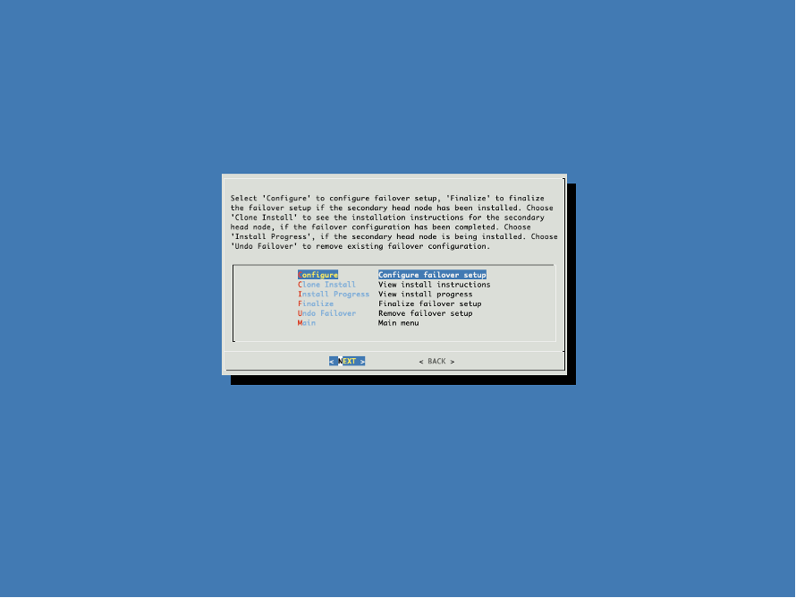
clio-headnode-01:~# cmha-setup
Choose Setup.
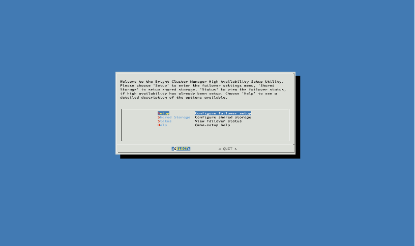
Choose Configure.
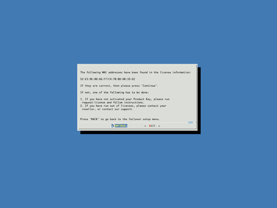
Verify the primary and stand-by BCM head-node MAC addresses and select CONTINUE.
Should the MAC addresses be incorrect, exit the script. Then, rerun the request-license command and select the option to keep the current license in the submenu. This action will allow you to modify only the MAC addresses for the headnodes.
Note
To prevent license issues due to a NIC failure/replacement, it is advisable to use the MAC address of the MLOM interface, if available.
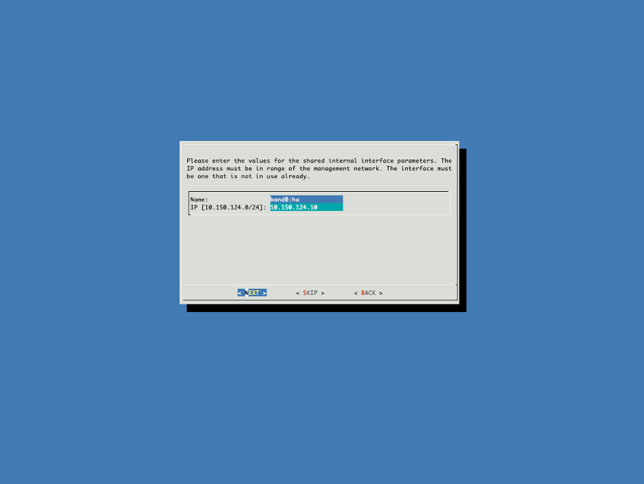
Populate the HA interface IP for bond0:ha and select NEXT.
This is the virtual IP address (VIP) for the BCM head-node HA Pair.
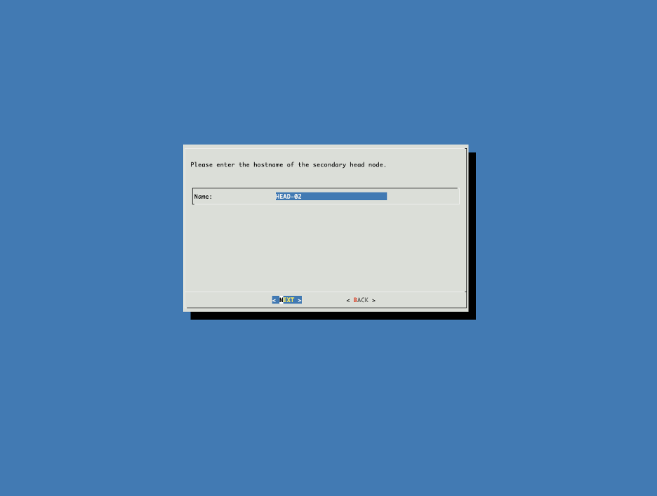
Set the name of the second head node according to the site survey.
Choose SKIP to skip the creation of the failovernet. We are going to use existing management for HA keepalives.
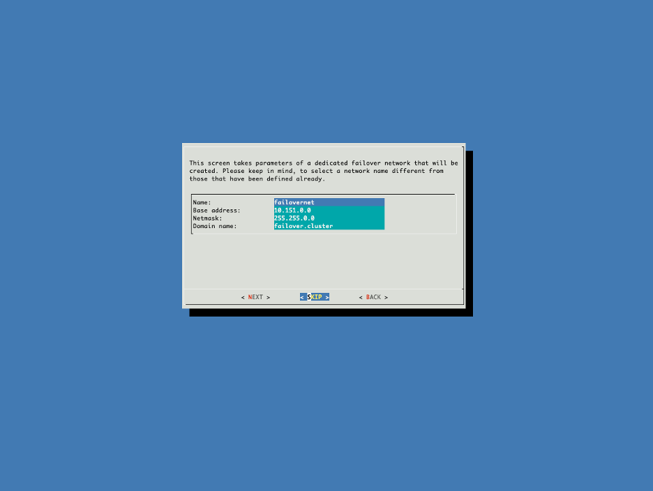
Refer to BCM11 Administrator Manual for more details on HA configuration options.
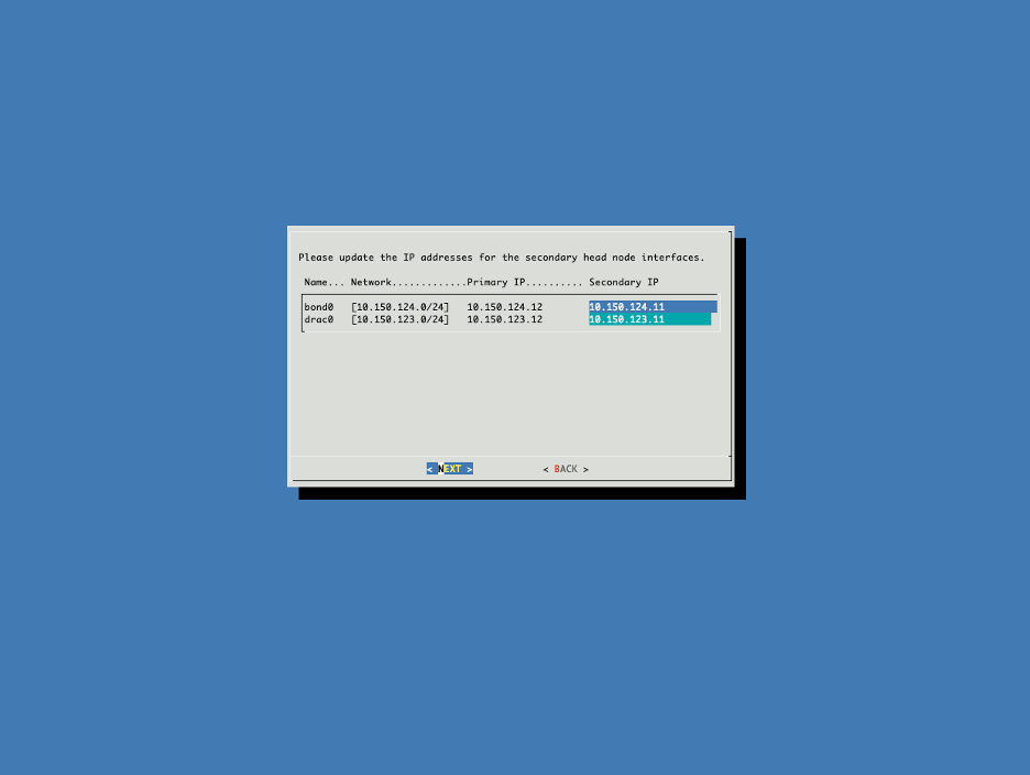
Set the in-band management and BMC IP addresses for the secondary head node.
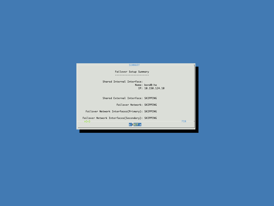
Check that all settings in the summary are correct and select EXIT.
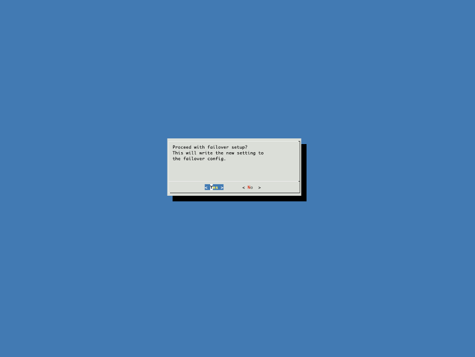
Select Yes to proceed with the failover config.
Enter the MYSQL password - which is the same as the BCM head-node root password - to continue.
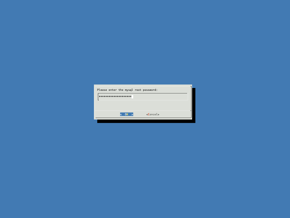
Once the below steps finish, press ENTER to continue.
Initializing failover setup on master.............. [  OK  ]
Updating shared internal interface................. [  OK  ]
Updating extra shared internal interfaces.......... [  OK  ]
Cloning head node.................................. [  OK  ]
Updating secondary master interfaces............... [  OK  ]
Updating Failover Object........................... [  OK  ]
Restarting cmdaemon................................ [  OK  ]
Press ENTER to continue
Boot the secondary BCM head-node and use its BMC KVM to select a one-time PXE boot from one of the in-band interfaces. The primary BCM head-node will then start PXE booting the secondary node. During the boot process, interrupt at the following screen and choose the RESCUE environment.
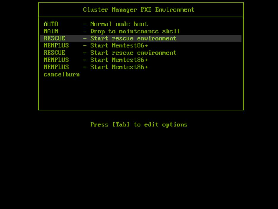
Once in the rescue environment, enter the /cm/cm-clone-install –failover command.
Then, provide the interface name of the primary in-band network, which will be used for the rest of the headnode installation prompts.
Note
If you are unsure of the interface name, check the primary headnode’s interface, as it will be the same for the secondary headnode. If the headnode interfaces are bonded, use the name of one of the child interfaces
root@ClusterManager:~# /cm/cm-clone-install --failover
Network interface to use [default: enp0]: enp138s0np0
.
.
.
root@master's password: <Root Cluster Password>
.
.
.
[v - view, e - edit, c - continue]: c
.
.
.
Do you want to continue [yes/no]? yes
.
.
.
Do you want to reboot [y/n]: y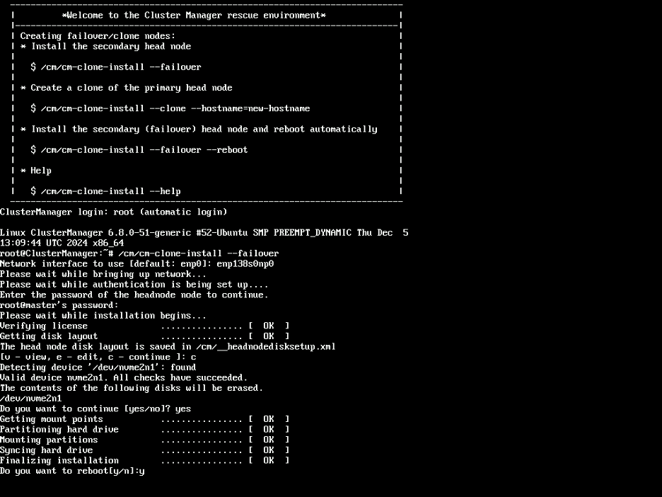
Wait until the secondary node completes the reboot. Then on the primary headnode, go back to the previous screen and select Finalize.
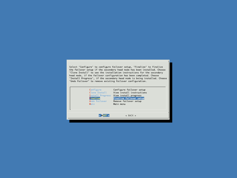
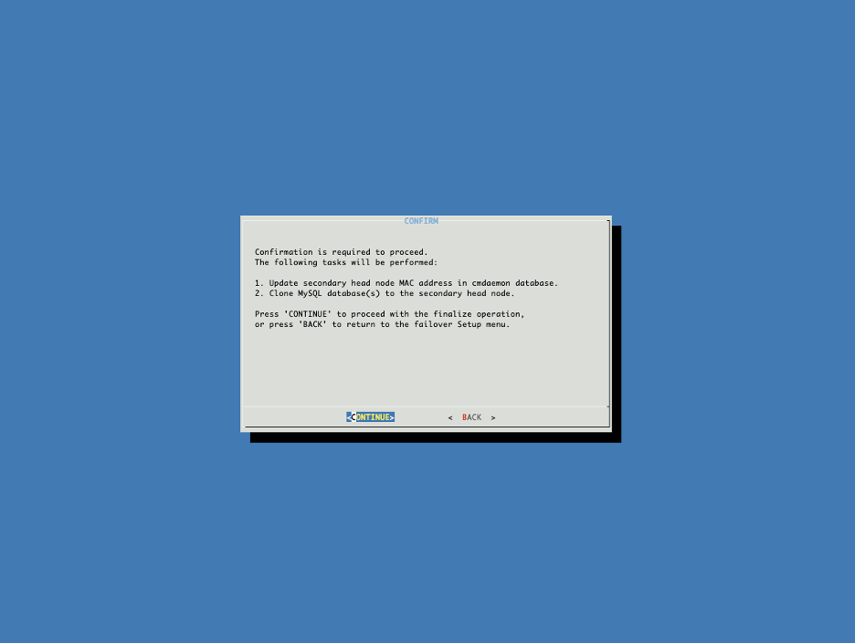
Select CONTINUE.
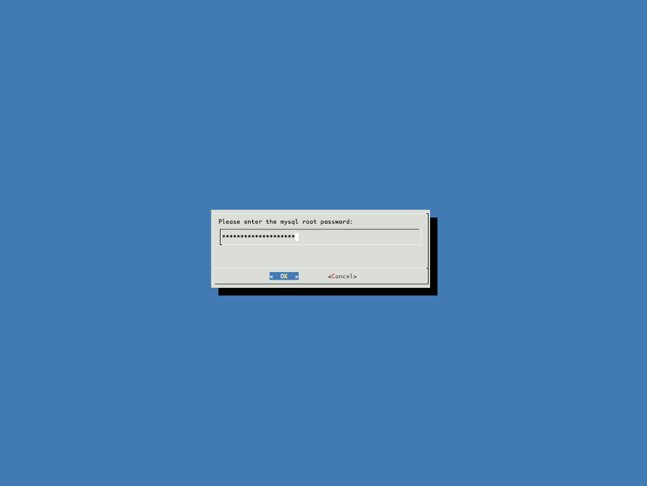
Enter the MYSQL password - which is the same as the BCM head-node root password - to continue.
Once the below steps are complete, press ENTER.
Updating secondary master mac address.............. [  OK  ]
Initializing failover setup on HEAD-02............. [  OK  ]
Stopping cmdaemon.................................. [  OK  ]
Cloning cmdaemon database.......................... [  OK  ]
Checking database consistency...................... [  OK  ]
Starting cmdaemon, chkconfig services.............. [  OK  ]
Cloning workload manager databases................. [  OK  ]
Cloning additional databases....................... [  OK  ]
Update DB permissions.............................. [  OK  ]
Checking for dedicated failover network............ [  OK  ]
Press ENTER to continue
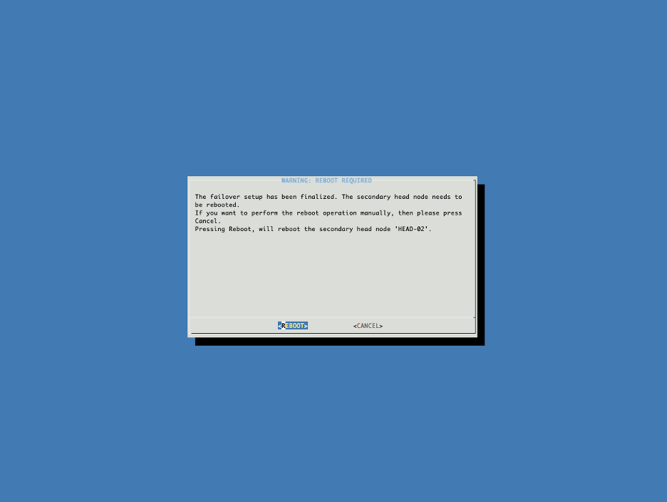
Choose to reboot the secondary headnode. Wait for the secondary headnode to come back up before continuing.
After reboot, you can verify the secondary node’s status from the primary head node using cmsh
[clio-headnode-01]% device list -f hostname:20,category:12,ip:20,status:15
hostname (key)       category     ip                   status
-------------------- ------------ -------------------- ---------------
clio-headnode-01                  10.150.124.11        [   UP   ]
clio-headnode-02                  10.150.124.12        [   UP   ]
[clio-headnode-01]%
Configuring NFS Shared Storage#
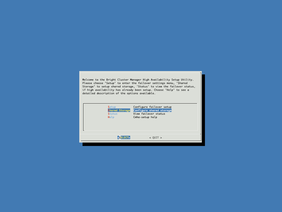
On the primary head node, continue in the HA setup screen (or start HA setup by running cmha-setup), select Shared Storage from the cmha-setup menu, and then select SELECT. In this final HA configuration step, cmha-setup will copy the /cm/shared and /home directories to the shared storage and configure both head nodes and all cluster nodes to mount it.
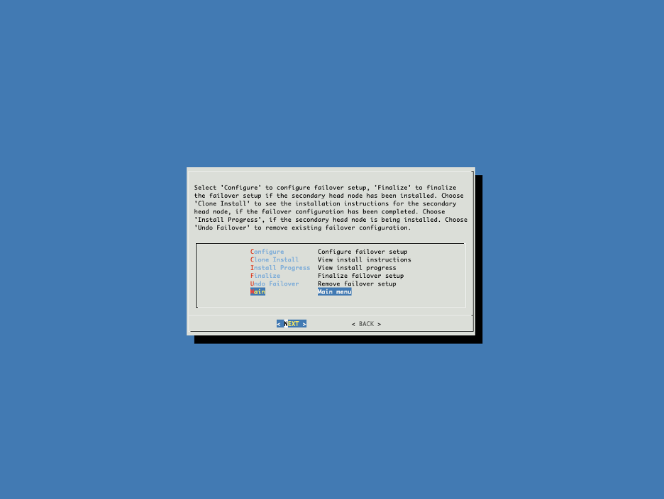
Select Shared Storage.
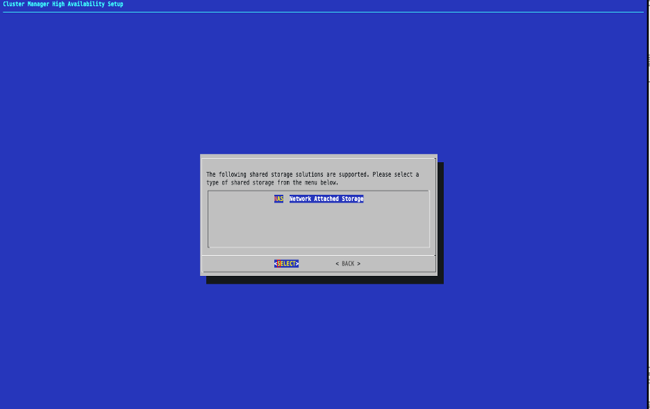
Select NAS
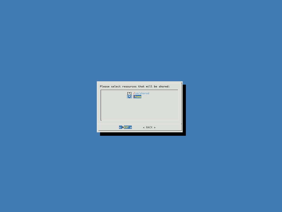
Select both /cm/shared and /home to be shared via NAS.
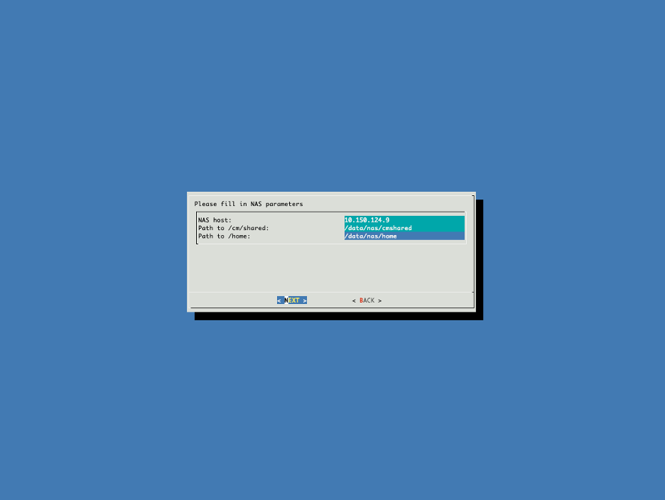
Set the NAS parameters.
Note
Ensure the full mount path (e.g. /data/nas/cmshared) exists in the NFS server
Proceed with the setup.
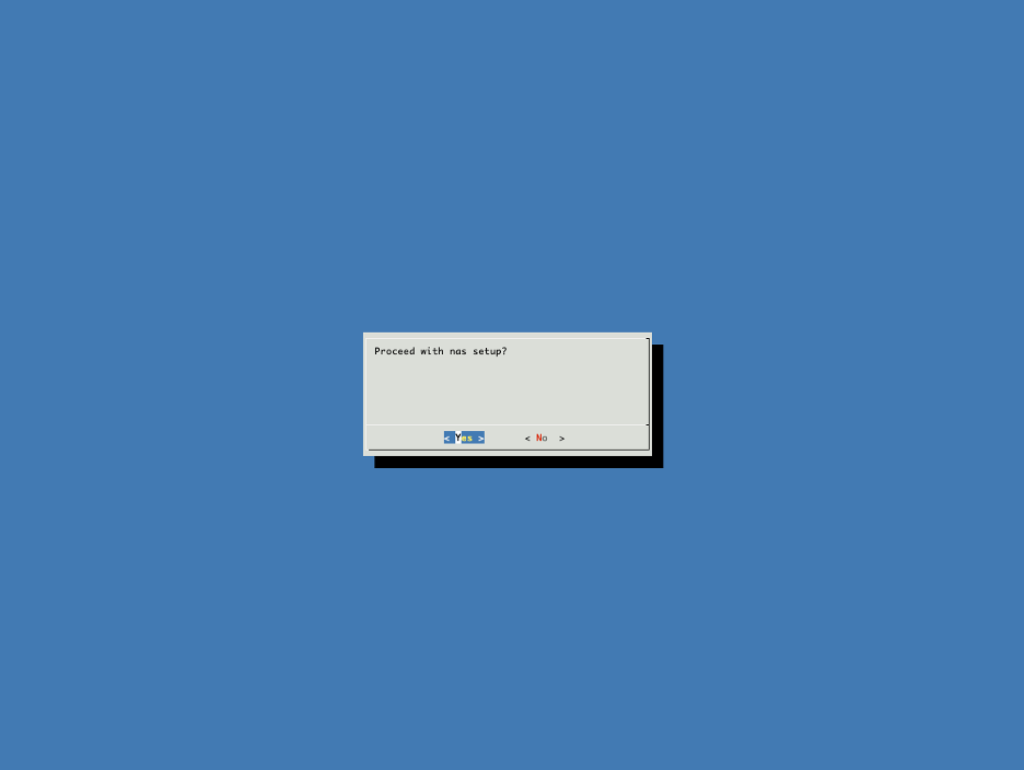
Once the below steps are complete, press ENTER.
Copying NAS data................................... [  OK  ]
Mount NAS storage.................................. [  OK  ]
Remove old fsmounts................................ [  OK  ]
Add new fsmounts................................... [  OK  ]
Disable old automatic fsexports.................... [  OK  ]
Press ENTER to continue
Exit the cmha-setup script.
Run cmha status to ensure HA is working.
clio-headnode-01:~# cmha status
Node Status: running in active mode

clio-headnode-01* -> Hclio-headnode-02
mysql           [  OK  ]
ping            [  OK  ]
status          [  OK  ]

clio-headnode-02 -> clio-headnode-01*
mysql           [  OK  ]
ping            [  OK  ]
status          [  OK  ]
Check the NFS mounts for /cm/shared and /home on the head node, and confirm they point to the NFS shared volume.
Head-node Primary
root@clio-headnode-01:~# mount | grep nfs
nfsd on /proc/fs/nfsd type nfsd (rw,relatime)
10.150.124.9:/data/nas/cmshared on /cm/shared type nfs (rw,relatime,vers=3,rsize=32768,wsize=32768,namlen=255,hard,proto=tcp,timeo=600,retrans=2,sec=sys,mountaddr=10.150.124.9,mountvers=3,mountport=44516,mountproto=udp,local_lock=none,addr=10.150.124.9)
10.150.124.9:/data/nas/home on /home type nfs (rw,relatime,vers=3,rsize=32768,wsize=32768,namlen=255,hard,proto=tcp,timeo=600,retrans=2,sec=sys,mountaddr=10.150.124.9,mountvers=3,mountport=44516,mountproto=udp,local_lock=none,addr=10.150.124.9)
root@clio-headnode-01:~#
Head-node Secondary
root@clio-headnode-02:~# mount | grep nfs
nfsd on /proc/fs/nfsd type nfsd (rw,relatime)
10.150.124.9:/data/nas/cmshared on /cm/shared type nfs (rw,relatime,vers=3,rsize=32768,wsize=32768,namlen=255,hard,proto=tcp,timeo=600,retrans=2,sec=sys,mountaddr=10.150.124.9,mountvers=3,mountport=44516,mountproto=udp,local_lock=none,addr=10.150.124.9)
10.150.124.9:/data/nas/home on /home type nfs (rw,relatime,vers=3,rsize=32768,wsize=32768,namlen=255,hard,proto=tcp,timeo=600,retrans=2,sec=sys,mountaddr=10.150.124.9,mountvers=3,mountport=44516,mountproto=udp,local_lock=none,addr=10.150.124.9)
root@clio-headnode-02:~#
Deploying Slurm#
Run the wlm install command from the root shell on the headnode
root@clio-headnode-01:~# cm-wlm-setup
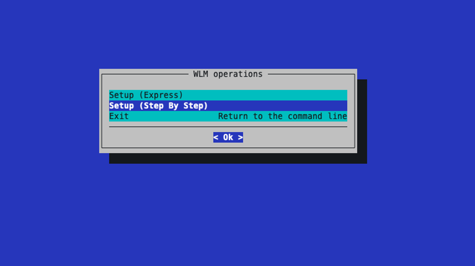
Select Setup (Step By Step)
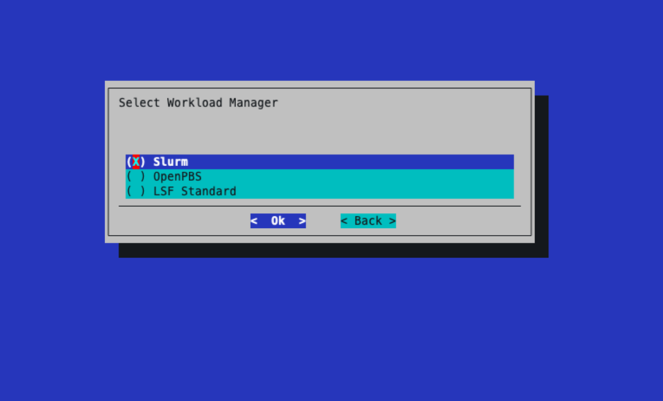
Select Slurm for the workload manager.
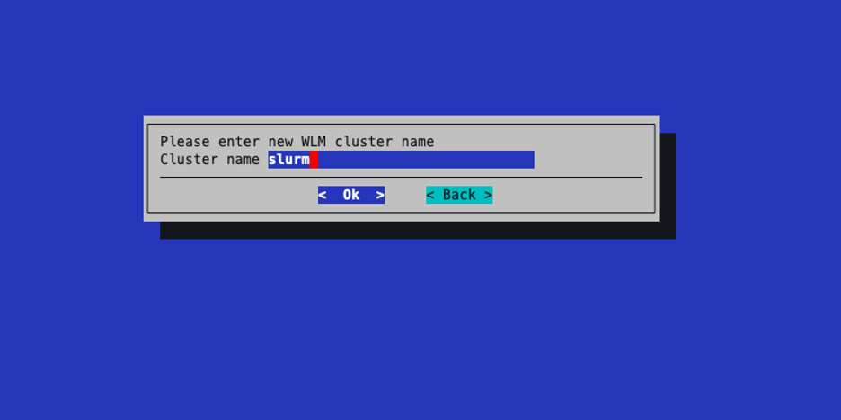
Leave the cluster name as the default.
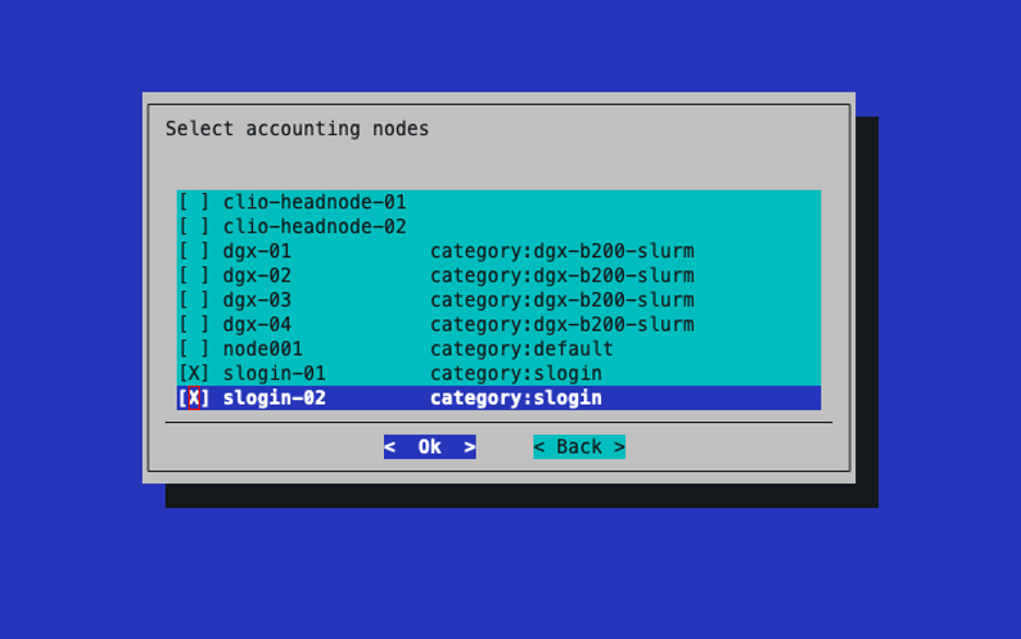
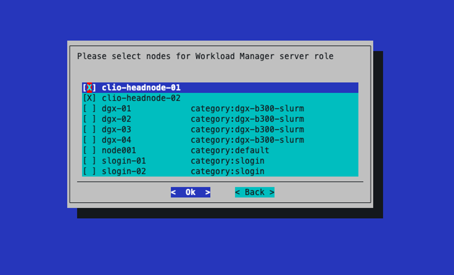
Select the two BCM head nodes for the server role.
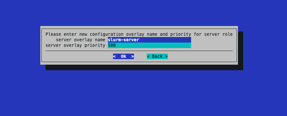
Leave the name and priority for the server overlay as defaults.
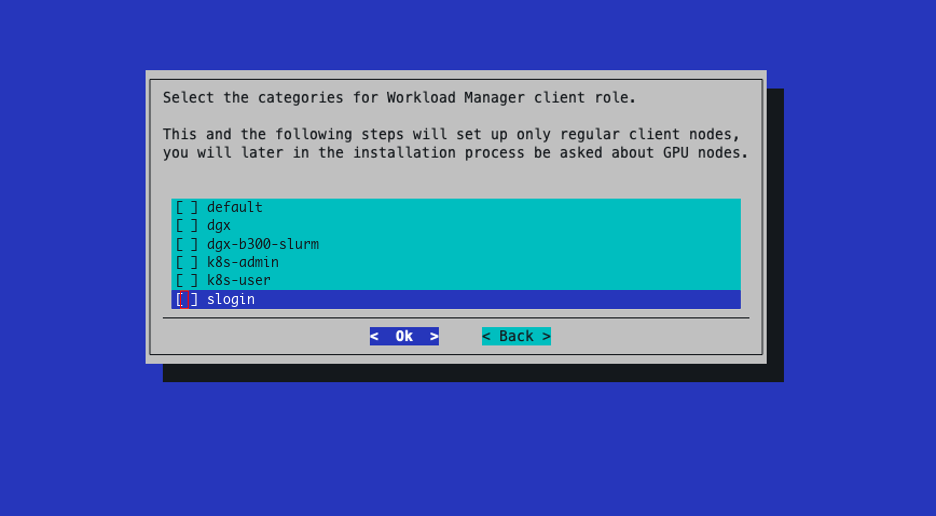
Do not select any categories for the client role.
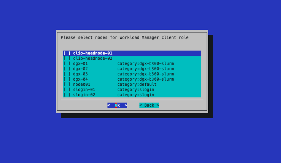
Do not select any nodes for the client role.
Leave the name and priority for the client overlay as defaults.
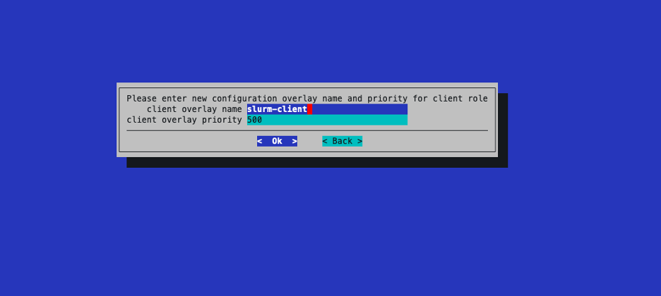
Select the following healthcheck producers to be run as prejob checks.
cm-chroot-sw-img
cuda-dcgm
diskspace
dmesg
failedprejob
gpuhealth_quick
mysql
oomkiller
rogueprocess
Schedulers
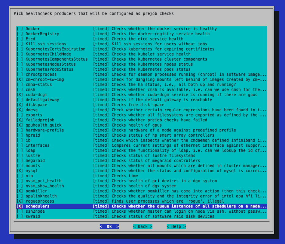
Select yes to configure GPUs.
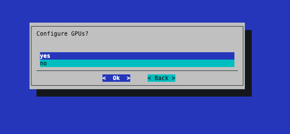
Leave the name of the GPU overlay as the default.
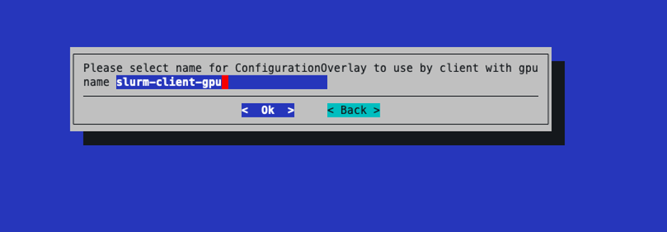
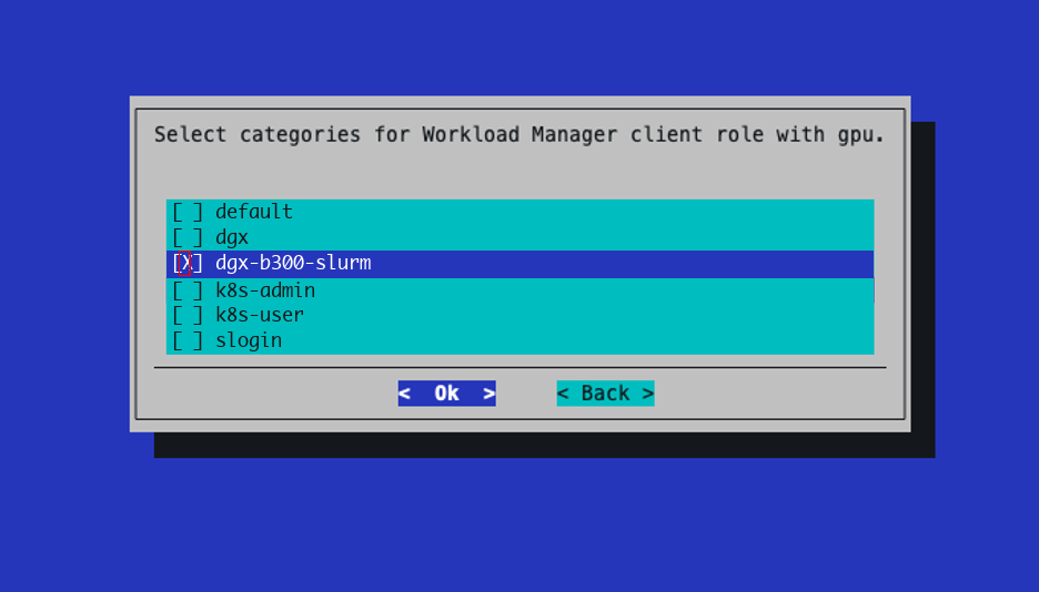
Select the dgx-b300-slurm category for Workload Manager client role with gpu.
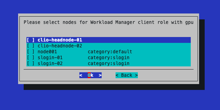
Do not select any nodes here.
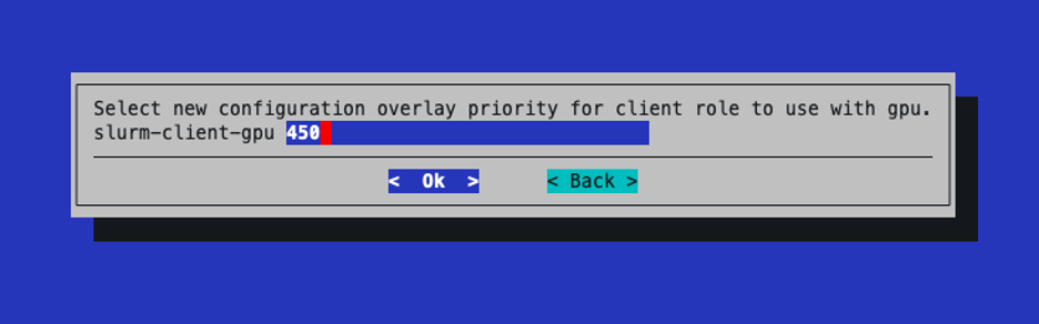
Leave the priority of the gpu client role as the default.
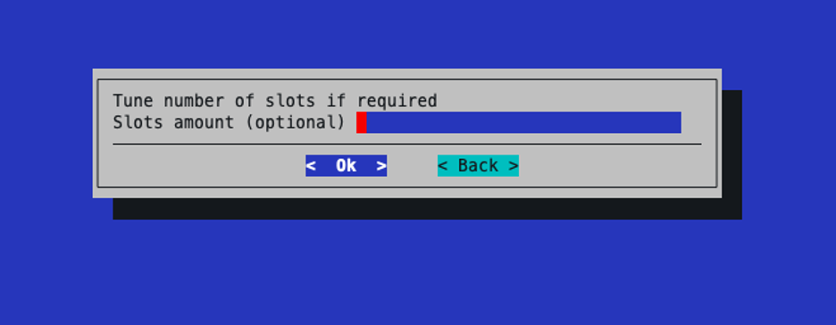
Leave the number of slots empty.
Select the slogin category for the submit role.
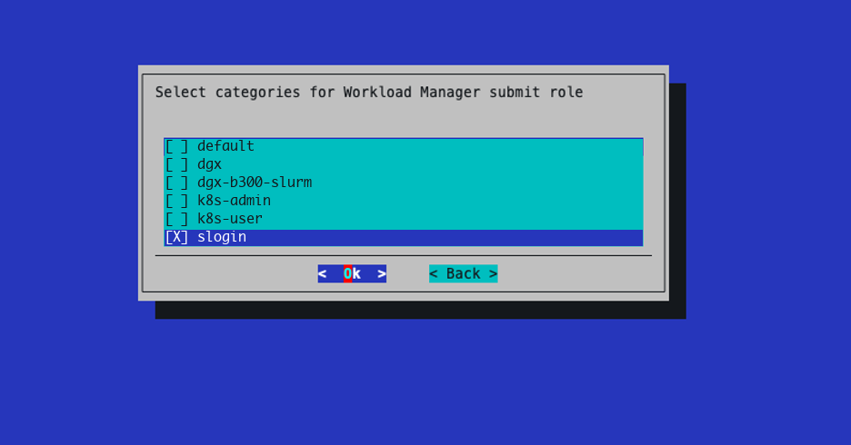
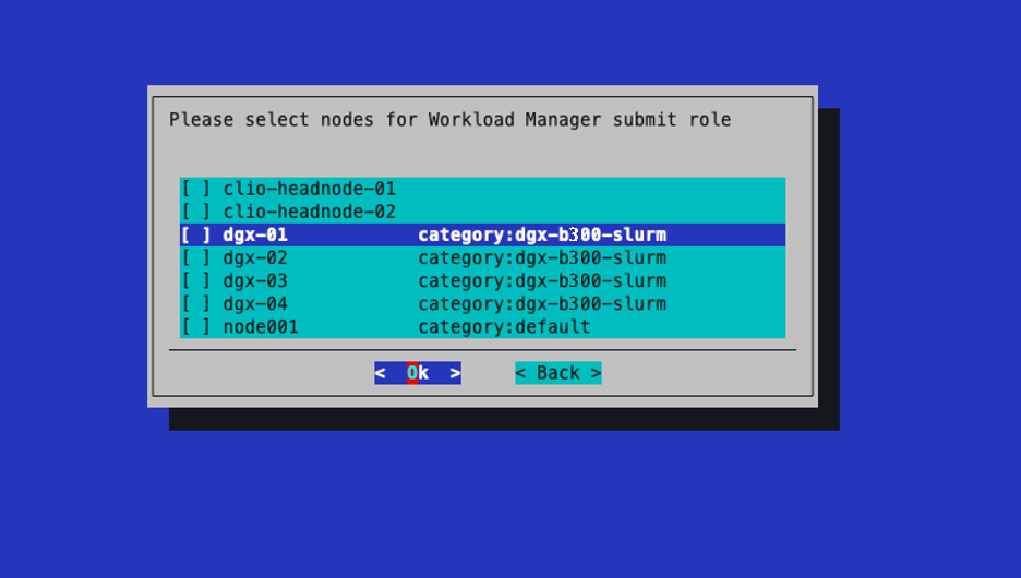
Do not select any additional nodes for the submit role.
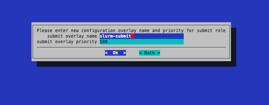
Leave the name and priority for the submit overlay as defaults.
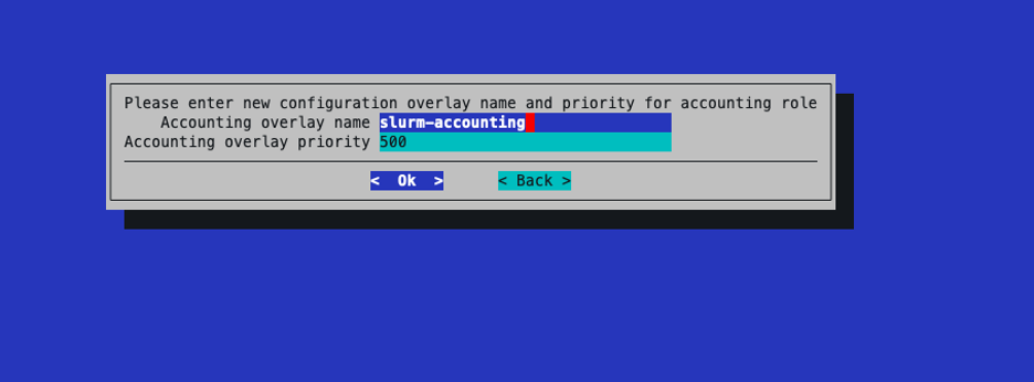
Leave the name and priority for the accounting overlay as defaults.
Select the head nodes for the accounting role.
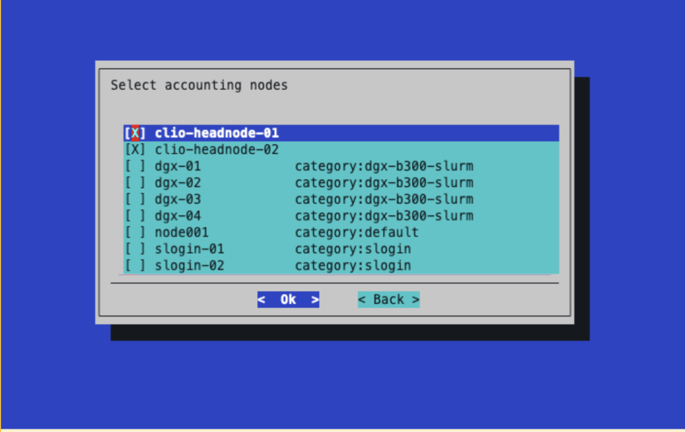
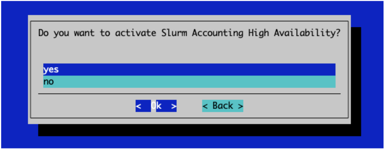
Select yes to enable Slurm Accounting High Availability.
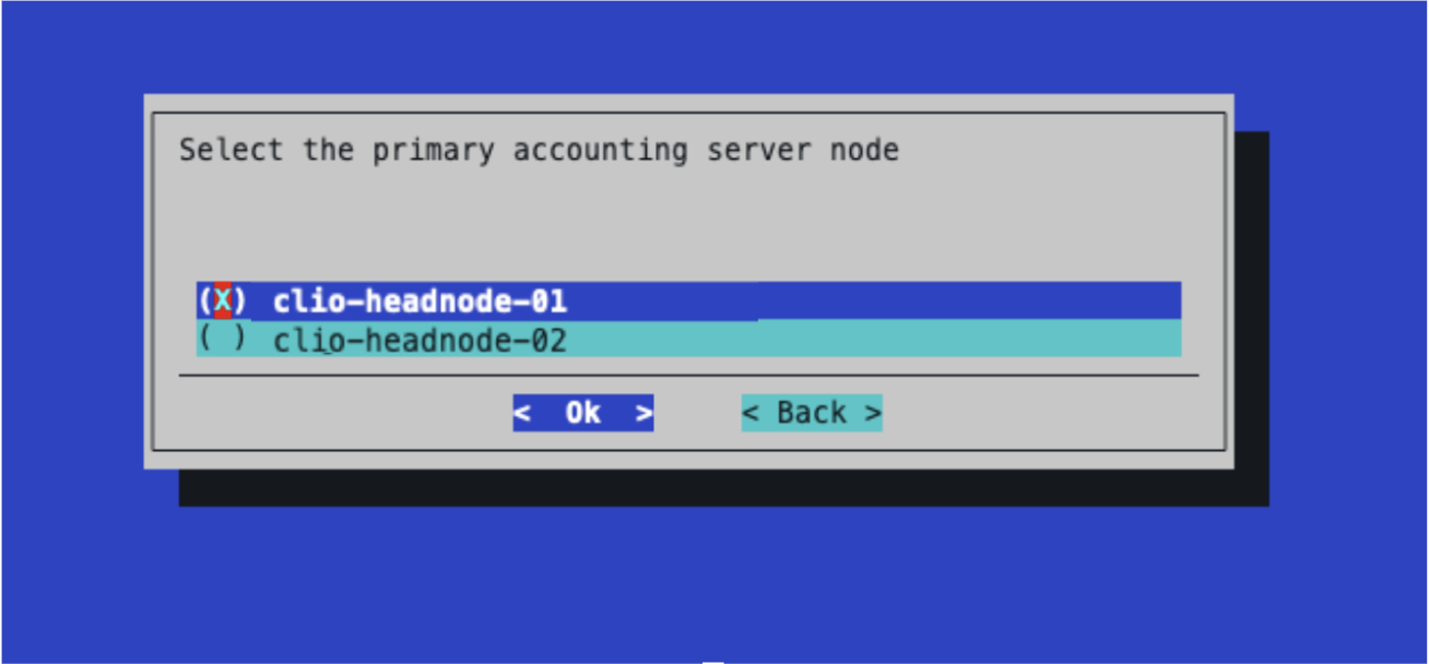
Select head-node-01 as the primary accounting node.
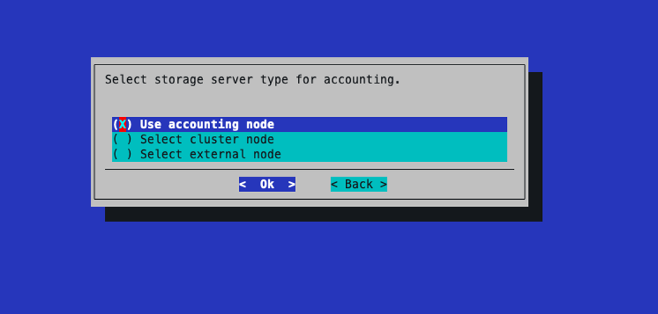
Select Use accounting node for the storage server type.
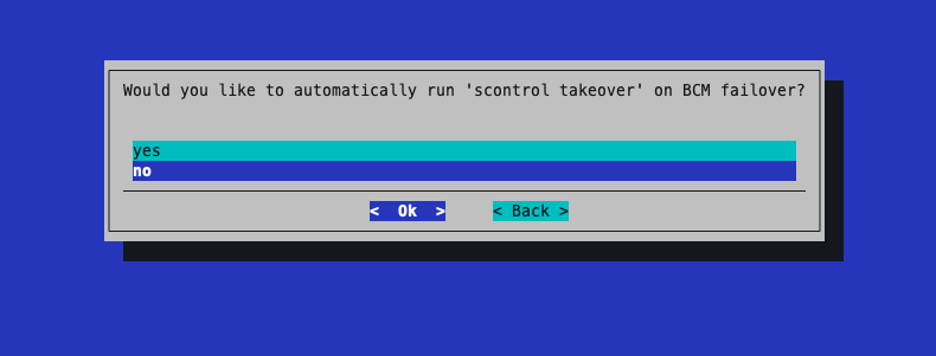
Select No on scontrol takeover on BCM failover
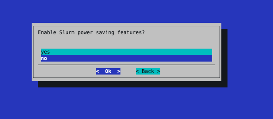
Select no for the Slurm power saving features.
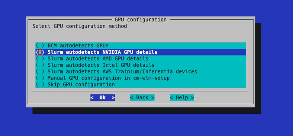
Select Slurm auto-detects NVIDIA GPU details.
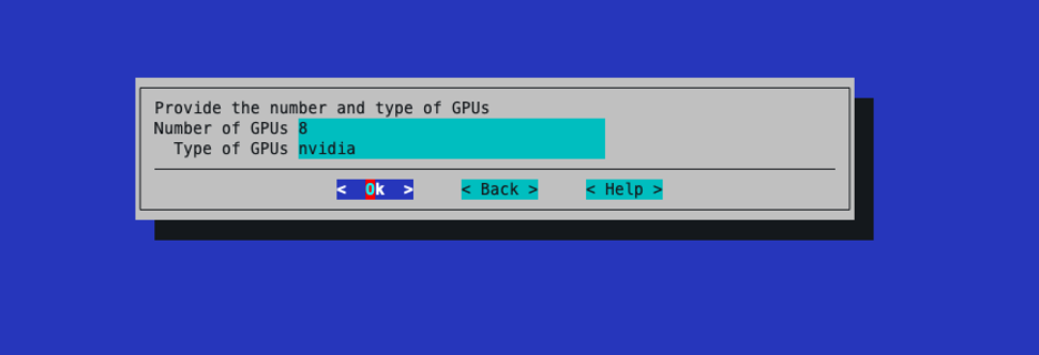
Set the number of GPUs to 8 and type to nvidia.
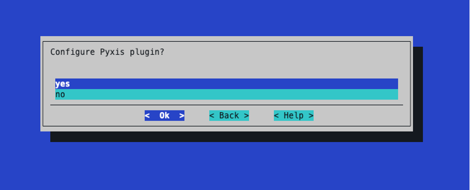
Select yes to configure the Pyxis plugin.
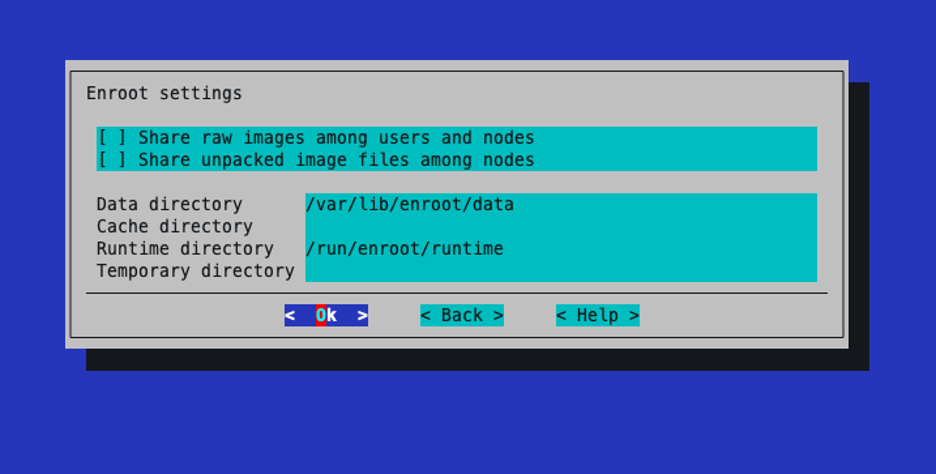
For Enroot settings, maintain the defaults, do not share data among the nodes or change the paths.
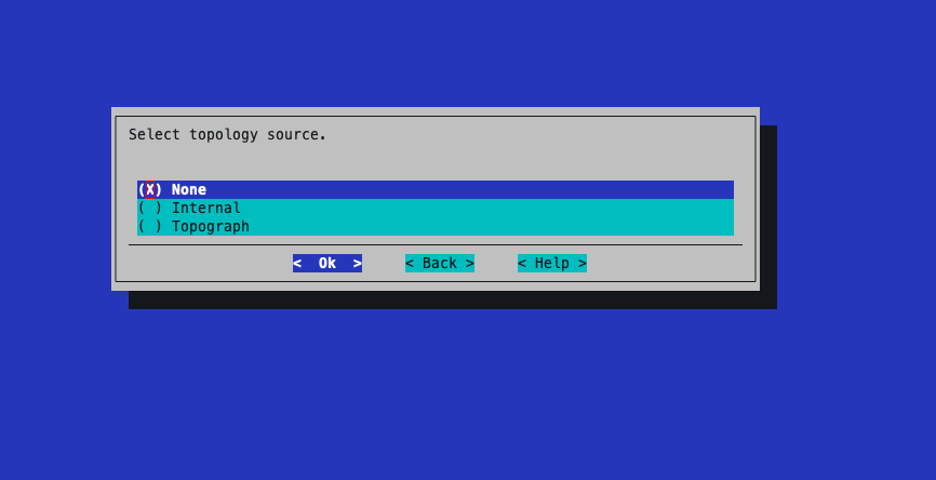
Select topology source as None
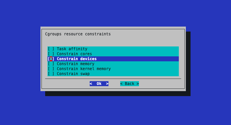
Select Constrain Devices for Cgroups resource constraints.
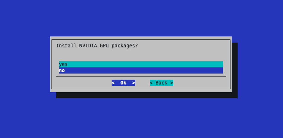
Select “no” on Install NVIDIA GPU packages.
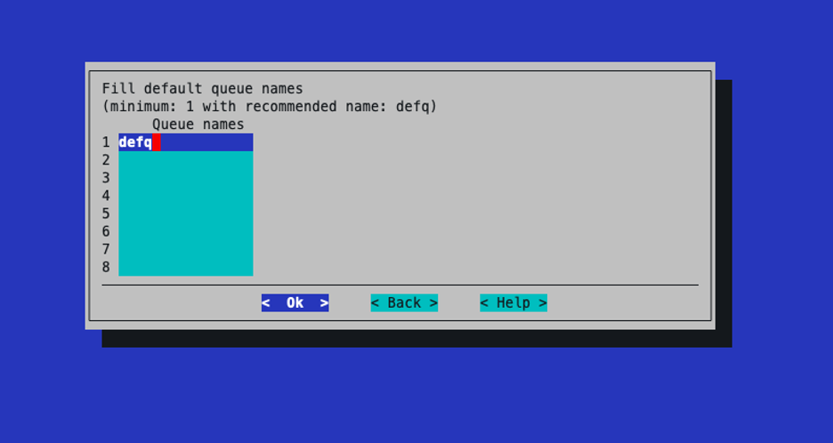
Leave the queue names as the default.
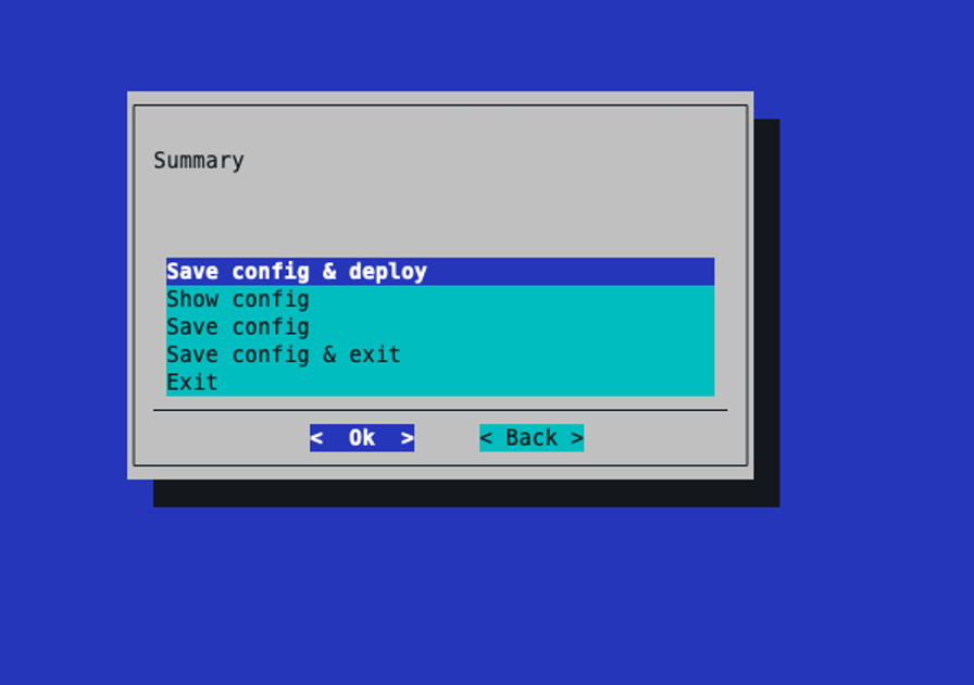
Choose Save config & deploy.
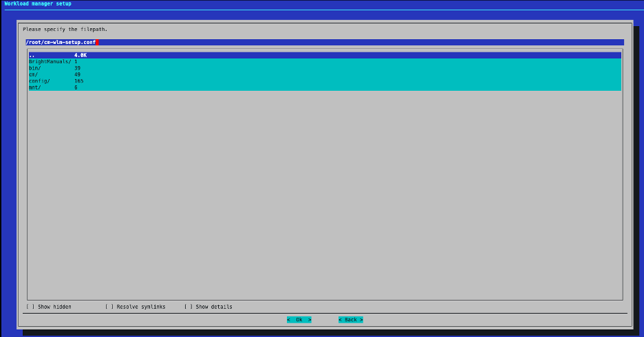
On the save screen you can proceed with the default values which places a cm-wlm-setup.conf file in the /root directory of the primary headnode, or you can specify a custom file name/directory. This file can be used in the future for redeploying Slurm using the same configuration values.
Wait for the installation to complete.
----- output omitted for brevity --------
## Progress: 73
#### stage: wlm_slurm: Create Job Queues
## Progress: 76
#### stage: wlm_slurm: Assign Server Role
Assigning SlurmServerRole role
## Progress: 77
#### stage: wlm: Set Primary Server
## Progress: 89
#### stage: wlm_slurm: Assign Client Role
Assigning SlurmClientRole role
## Progress: 90
#### stage: wlm_slurm: Assign SlurmClientRole to configuration overlays with gpu
GPU devices will automatically be added to gres.conf.
Please configure consumable resource allocation and GPU accounting tracking plugins in slurm.conf manually if needed.
More details can be found in the Bright Computing administrator manual, section "GPU Configuration For HPC Workload Managers".
## Progress: 91
#### stage: wlm_slurm: Assign Submit Role
Assigning SlurmSubmitRole role
#### stage: wlm_slurm: Assign Headnode Submit Role
Assigning SlurmSubmitRole role
## Progress: 92
#### stage: wlm_slurm: Render SlurmSubmit role intersection with other installations
## Progress: 93
#### stage: wlm_slurm: Assign Accounting Role
Assigning SlurmAccountingRole role
## Progress: 94
#### stage: wlm: Update Prejob Healthchecks
## Progress: 100

Took:     01:13 min.
Progress: 100/100
################### Finished execution for 'Workload manager setup', status: completed

Workload manager setup finished!
Remove the slurm-client overlay since there will not be any slurm cpu workers.
root@clio-headnode-01:~# cmsh
[root@clio-headnode-01]% configurationoverlay
[root@clio-headnode-01->configurationoverlay]% remove slurm-client
[root@clio-headnode-01->configurationoverlay*]% commit
Successfully removed 1 ConfigurationOverlays
Successfully committed 0 ConfigurationOverlays
Rename the slurm-gpu-client overlay
[clio-headnode-01->configurationoverlay]% set slurm-client-gpu name slurm-client
[clio-headnode-01->configurationoverlay*]% commit
Successfully committed 1 ConfigurationOverlays
Validate Slurm#
Login to SLOGIN-01 and run sinfo to verify that all the nodes are up and ready.
root@slogin-01:~# module load slurm
root@slogin-01:~# sinfo
PARTITION AVAIL  TIMELIMIT  NODES  STATE NODELIST
defq*        up   infinite      4   idle dgx-[01-04]
Basic Slurm job/GPU test
root@slogin-01:~# srun --gres=gpu:1 -n1 nvidia-smi
Fri Jul 31 09:18:10 2026
+-----------------------------------------------------------------------------------------+
| NVIDIA-SMI 580.126.20             Driver Version: 580.126.20     CUDA Version: 13.0     |
+-----------------------------------------+------------------------+----------------------+
| GPU  Name                 Persistence-M | Bus-Id          Disp.A | Volatile Uncorr. ECC |
| Fan  Temp   Perf          Pwr:Usage/Cap |           Memory-Usage | GPU-Util  Compute M. |
|                                         |                        |               MIG M. |
|=========================================+========================+======================|
|   0  NVIDIA B300 SXM6 AC            On  |   00000000:1A:00.0 Off |                    0 |
| N/A   30C    P0            135W / 1100W |       0MiB / 275040MiB |      0%      Default |
|                                         |                        |             Disabled |
+-----------------------------------------+------------------------+----------------------+

+-----------------------------------------------------------------------------------------+
| Processes:                                                                              |
|  GPU   GI   CI              PID   Type   Process name                        GPU Memory |
|        ID   ID                                                               Usage      |
|=========================================================================================|
|  No running processes found                                                             |
+-----------------------------------------------------------------------------------------+
root@slogin-01:~# srun --gres=gpu:8 -n1 nvidia-smi
Fri Jul 31 09:18:10 2026
+-----------------------------------------------------------------------------------------+
| NVIDIA-SMI 580.126.20             Driver Version: 580.126.20     CUDA Version: 13.0     |
+-----------------------------------------+------------------------+----------------------+
| GPU  Name                 Persistence-M | Bus-Id          Disp.A | Volatile Uncorr. ECC |
| Fan  Temp   Perf          Pwr:Usage/Cap |           Memory-Usage | GPU-Util  Compute M. |
|                                         |                        |               MIG M. |
|=========================================+========================+======================|
|   0  NVIDIA B300 SXM6 AC            On  |   00000000:1A:00.0 Off |                    0 |
| N/A   30C    P0            135W / 1100W |       0MiB / 275040MiB |      0%      Default |
|                                         |                        |             Disabled |
+-----------------------------------------+------------------------+----------------------+
|   1  NVIDIA B300 SXM6 AC            On  |   00000000:3C:00.0 Off |                    0 |
| N/A   30C    P0            136W / 1100W |       0MiB / 275040MiB |      0%      Default |
|                                         |                        |             Disabled |
+-----------------------------------------+------------------------+----------------------+
|   2  NVIDIA B300 SXM6 AC            On  |   00000000:62:00.0 Off |                    0 |
| N/A   33C    P0            138W / 1100W |       0MiB / 275040MiB |      0%      Default |
|                                         |                        |             Disabled |
+-----------------------------------------+------------------------+----------------------+
|   3  NVIDIA B300 SXM6 AC            On  |   00000000:73:00.0 Off |                    0 |
| N/A   32C    P0            136W / 1100W |       0MiB / 275040MiB |      0%      Default |
|                                         |                        |             Disabled |
+-----------------------------------------+------------------------+----------------------+
|   4  NVIDIA B300 SXM6 AC            On  |   00000000:9A:00.0 Off |                    0 |
| N/A   30C    P0            136W / 1100W |       0MiB / 275040MiB |      0%      Default |
|                                         |                        |             Disabled |
+-----------------------------------------+------------------------+----------------------+
|   5  NVIDIA B300 SXM6 AC            On  |   00000000:BC:00.0 Off |                    0 |
| N/A   30C    P0            138W / 1100W |       0MiB / 275040MiB |      0%      Default |
|                                         |                        |             Disabled |
+-----------------------------------------+------------------------+----------------------+
|   6  NVIDIA B300 SXM6 AC            On  |   00000000:DF:00.0 Off |                    0 |
| N/A   33C    P0            138W / 1100W |       0MiB / 275040MiB |      0%      Default |
|                                         |                        |             Disabled |
+-----------------------------------------+------------------------+----------------------+
|   7  NVIDIA B300 SXM6 AC            On  |   00000000:F0:00.0 Off |                    0 |
| N/A   33C    P0            134W / 1100W |       0MiB / 275040MiB |      0%      Default |
|                                         |                        |             Disabled |
+-----------------------------------------+------------------------+----------------------+

+-----------------------------------------------------------------------------------------+
| Processes:                                                                              |
|  GPU   GI   CI              PID   Type   Process name                        GPU Memory |
|        ID   ID                                                               Usage      |
|=========================================================================================|
|  No running processes found                                                             |
+-----------------------------------------------------------------------------------------+
Container validation test#
root@slogin-01:~# srun --container-image=ubuntu  grep PRETTY /etc/os-release
pyxis: importing docker image: ubuntu
pyxis: imported docker image: ubuntu
PRETTY_NAME="Ubuntu 24.04.2 LTS"
Single-node NCCL test#
root@slogin-01:~# srun --export="NCCL_SOCKET_IFNAME=bond0" -N1 --exclusive --gpus-per-node=8 --mpi=pmix --container-name=nccl-test --container-image="docker://brightcomputing/nccl-test:25.02-py3-x86" all_reduce_perf_mpi -b 1G -e 16G -f 2 -g 8
# nThread 1 nGpus 8 minBytes 1073741824 maxBytes 17179869184 step: 2(factor) warmup iters: 5 iters: 20 agg iters: 1 validation: 1 graph: 0
#
# Using devices
#  Rank  0 Group  0 Pid  67104 on     dgx-02 device  0 [0x1b] NVIDIA B300
#  Rank  1 Group  0 Pid  67104 on     dgx-02 device  1 [0x43] NVIDIA B300
#  Rank  2 Group  0 Pid  67104 on     dgx-02 device  2 [0x52] NVIDIA B300
#  Rank  3 Group  0 Pid  67104 on     dgx-02 device  3 [0x61] NVIDIA B300
#  Rank  4 Group  0 Pid  67104 on     dgx-02 device  4 [0x9d] NVIDIA B300
#  Rank  5 Group  0 Pid  67104 on     dgx-02 device  5 [0xc3] NVIDIA B300
#  Rank  6 Group  0 Pid  67104 on     dgx-02 device  6 [0xd1] NVIDIA B300
#  Rank  7 Group  0 Pid  67104 on     dgx-02 device  7 [0xdf] NVIDIA B300
#
#                                                              out-of-place                       in-place
#       size         count      type   redop    root     time   algbw   busbw #wrong     time   algbw   busbw #wrong
#        (B)    (elements)                               (us)  (GB/s)  (GB/s)            (us)  (GB/s)  (GB/s)
1073741824     268435456     float     sum      -1   2587.7  414.94  726.15      0   2582.9  415.71  727.50      0
2147483648     536870912     float     sum      -1   4628.4  463.98  811.96      0   4634.3  463.39  810.93      0
4294967296    1073741824     float     sum      -1   9114.2  471.24  824.67      0   9114.2  471.24  824.67      0
8589934592    2147483648     float     sum      -1    18081  475.07  831.38      0    18092  474.80  830.90      0
17179869184    4294967296     float     sum      -1    36048  476.58  834.02      0    36024  476.91  834.58      0
# Out of bounds values : 0 OK
# Avg bus bandwidth    : 805.674
#
Multinode NCCL Test 2 and 3 nodes#
root@slogin-01:~#  srun --export="UCX_NET_DEVICES=bond0,OMPI_MCA_pml=ucx,HCOLL_ENABLE_MCAST_ALL=0,OMPI_MCA_coll=^hcoll,NCCL_SOCKET_IFNAME=bond0,UCX_TLS=tcp,UCX_NET_DEVICES=bond0,MELLANOX_VISIBLE_DEVICES=all,OMPI_MCA_coll_hcoll_enable=0,OMPI_MCA_coll_ucc_enable=0" -N2 --exclusive --gpus-per-node=8 --mpi=pmix --container-name=nccl-test --container-image="docker://brightcomputing/nccl-test:25.02-py3-x86" all_reduce_perf_mpi -b 1G -e 16G -f 2 -g 8
[dgx-04:74971] PMIX ERROR: ERROR in file gds_ds12_lock_pthread.c at line 168
[dgx-02:75241] PMIX ERROR: ERROR in file gds_ds12_lock_pthread.c at line 168
# nThread 1 nGpus 8 minBytes 1073741824 maxBytes 17179869184 step: 2(factor) warmup iters: 5 iters: 20 agg iters: 1 validation: 1 graph: 0
#
# Using devices
#  Rank  0 Group  0 Pid  75241 on     dgx-02 device  0 [0x1b] NVIDIA B300
#  Rank  1 Group  0 Pid  75241 on     dgx-02 device  1 [0x43] NVIDIA B300
#  Rank  2 Group  0 Pid  75241 on     dgx-02 device  2 [0x52] NVIDIA B300
#  Rank  3 Group  0 Pid  75241 on     dgx-02 device  3 [0x61] NVIDIA B300
#  Rank  4 Group  0 Pid  75241 on     dgx-02 device  4 [0x9d] NVIDIA B300
#  Rank  5 Group  0 Pid  75241 on     dgx-02 device  5 [0xc3] NVIDIA B300
#  Rank  6 Group  0 Pid  75241 on     dgx-02 device  6 [0xd1] NVIDIA B300
#  Rank  7 Group  0 Pid  75241 on     dgx-02 device  7 [0xdf] NVIDIA B300
#  Rank  8 Group  0 Pid  74971 on     dgx-04 device  0 [0x1b] NVIDIA B300
#  Rank  9 Group  0 Pid  74971 on     dgx-04 device  1 [0x43] NVIDIA B300
#  Rank 10 Group  0 Pid  74971 on     dgx-04 device  2 [0x52] NVIDIA B300
#  Rank 11 Group  0 Pid  74971 on     dgx-04 device  3 [0x61] NVIDIA B300
#  Rank 12 Group  0 Pid  74971 on     dgx-04 device  4 [0x9d] NVIDIA B300
#  Rank 13 Group  0 Pid  74971 on     dgx-04 device  5 [0xc3] NVIDIA B300
#  Rank 14 Group  0 Pid  74971 on     dgx-04 device  6 [0xd1] NVIDIA B300
#  Rank 15 Group  0 Pid  74971 on     dgx-04 device  7 [0xdf] NVIDIA B300
#
#                                                              out-of-place                       in-place
#       size         count      type   redop    root     time   algbw   busbw #wrong     time   algbw   busbw #wrong
#        (B)    (elements)                               (us)  (GB/s)  (GB/s)            (us)  (GB/s)  (GB/s)
1073741824     268435456     float     sum      -1   2972.6  361.22  677.28      0   2975.6  360.84  676.58      0
2147483648     536870912     float     sum      -1   5710.7  376.04  705.08      0   5712.2  375.95  704.90      0
4294967296    1073741824     float     sum      -1    11185  384.00  720.00      0    11186  383.96  719.93      0
8589934592    2147483648     float     sum      -1    22124  388.26  727.98      0    22123  388.28  728.02      0
17179869184    4294967296     float     sum      -1    44009  390.37  731.95      0    44000  390.45  732.09      0
# Out of bounds values : 0 OK
# Avg bus bandwidth    : 712.381
#


## ---- 3 node NCCL test ----##
root@slogin-01:~# srun --export="UCX_NET_DEVICES=bond0,OMPI_MCA_pml=ucx,HCOLL_ENABLE_MCAST_ALL=0,OMPI_MCA_coll=^hcoll,NCCL_SOCKET_IFNAME=bond0,UCX_TLS=tcp,UCX_NET_DEVICES=bond0,MELLANOX_VISIBLE_DEVICES=all,OMPI_MCA_coll_hcoll_enable=0,OMPI_MCA_coll_ucc_enable=0" -N3 --exclusive --gpus-per-node=8 --mpi=pmix --container-name=nccl-test --container-image="docker://brightcomputing/nccl-test:25.02-py3-x86" all_reduce_perf_mpi -b 1G -e 16G -f 2 -g 8
[dgx-04:90178] PMIX ERROR: ERROR in file gds_ds12_lock_pthread.c at line 168
[dgx-02:90762] PMIX ERROR: ERROR in file gds_ds12_lock_pthread.c at line 168
pyxis: imported docker image: docker://brightcomputing/nccl-test:25.02-py3-x86
[dgx-01:80425] PMIX ERROR: ERROR in file gds_ds12_lock_pthread.c at line 168
# nThread 1 nGpus 8 minBytes 1073741824 maxBytes 17179869184 step: 2(factor) warmup iters: 5 iters: 20 agg iters: 1 validation: 1 graph: 0
#
# Using devices
#  Rank  0 Group  0 Pid  80425 on     dgx-01 device  0 [0x1b] NVIDIA B300
#  Rank  1 Group  0 Pid  80425 on     dgx-01 device  1 [0x43] NVIDIA B300
#  Rank  2 Group  0 Pid  80425 on     dgx-01 device  2 [0x52] NVIDIA B300
#  Rank  3 Group  0 Pid  80425 on     dgx-01 device  3 [0x61] NVIDIA B300
#  Rank  4 Group  0 Pid  80425 on     dgx-01 device  4 [0x9d] NVIDIA B300
#  Rank  5 Group  0 Pid  80425 on     dgx-01 device  5 [0xc3] NVIDIA B300
#  Rank  6 Group  0 Pid  80425 on     dgx-01 device  6 [0xd1] NVIDIA B300
#  Rank  7 Group  0 Pid  80425 on     dgx-01 device  7 [0xdf] NVIDIA B300
#  Rank  8 Group  0 Pid  90762 on     dgx-02 device  0 [0x1b] NVIDIA B300
#  Rank  9 Group  0 Pid  90762 on     dgx-02 device  1 [0x43] NVIDIA B300
#  Rank 10 Group  0 Pid  90762 on     dgx-02 device  2 [0x52] NVIDIA B300
#  Rank 11 Group  0 Pid  90762 on     dgx-02 device  3 [0x61] NVIDIA B300
#  Rank 12 Group  0 Pid  90762 on     dgx-02 device  4 [0x9d] NVIDIA B300
#  Rank 13 Group  0 Pid  90762 on     dgx-02 device  5 [0xc3] NVIDIA B300
#  Rank 14 Group  0 Pid  90762 on     dgx-02 device  6 [0xd1] NVIDIA B300
#  Rank 15 Group  0 Pid  90762 on     dgx-02 device  7 [0xdf] NVIDIA B300
#  Rank 16 Group  0 Pid  90178 on     dgx-04 device  0 [0x1b] NVIDIA B300
#  Rank 17 Group  0 Pid  90178 on     dgx-04 device  1 [0x43] NVIDIA B300
#  Rank 18 Group  0 Pid  90178 on     dgx-04 device  2 [0x52] NVIDIA B300
#  Rank 19 Group  0 Pid  90178 on     dgx-04 device  3 [0x61] NVIDIA B300
#  Rank 20 Group  0 Pid  90178 on     dgx-04 device  4 [0x9d] NVIDIA B300
#  Rank 21 Group  0 Pid  90178 on     dgx-04 device  5 [0xc3] NVIDIA B300
#  Rank 22 Group  0 Pid  90178 on     dgx-04 device  6 [0xd1] NVIDIA B300
#  Rank 23 Group  0 Pid  90178 on     dgx-04 device  7 [0xdf] NVIDIA B300
#
#                                                              out-of-place                       in-place
#       size         count      type   redop    root     time   algbw   busbw #wrong     time   algbw   busbw #wrong
#        (B)    (elements)                               (us)  (GB/s)  (GB/s)            (us)  (GB/s)  (GB/s)
1073741824     268435456     float     sum      -1   5322.5  201.74  386.66      0   5326.0  201.60  386.41      0
2147483648     536870912     float     sum      -1    10562  203.31  389.68      0    10560  203.36  389.77      0
4294967296    1073741824     float     sum      -1    20999  204.53  392.02      0    21009  204.44  391.84      0
8589934592    2147483648     float     sum      -1    42028  204.38  391.74      0    42038  204.34  391.65      0
17179869184    4294967296     float     sum      -1    83647  205.39  393.66      0    83650  205.38  393.64      0
# Out of bounds values : 0 OK
# Avg bus bandwidth    : 390.707
Deploy Run:ai#
Refer to the official Run:ai on BCM installation documentation for step-by-step deployment guides based on the BCM K8s deployment wizard.
Cluster Name#
To help distinguish the Run:ai cluster from other K8s clusters that may be deployed onto the SuperPOD, set the cluster name to k8s-user in the Kubernetes Wizard.
Node Categories#
In the NVIDIA Base Command Manager (BCM), a node category is a way to group nodes that share the same hardware profile and intended role. Defining node categories allows the system to assign the appropriate software image and configurations to each group during provisioning
Before installing NVIDIA Run:ai, make sure BCM node categories are created for:
Kubernetes system nodes ( k8s-system-user)
NVIDIA Run:ai GPU worker nodes (dgx-b300-k8s)
These will be employed when setting up Run:ai for the first time via the BCM setup assistant. More details and full instructions are available in the Run:ai BCM Install Getting Started Guide .
Validate Run:AI#
To validate Run:AI, refer to the Run:AI usage guides for deploying single-GPU training jobs, multi-node training jobs, single-GPU inference jobs, and multi-GPU inference jobs.