Deploying the Bundles#
Cables entering a network rack can be said to enter in one of three ways:
Top feed.
Bottom feed.
Top/bottom feed.
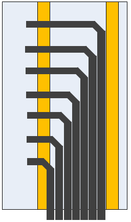
Top and bottom feeds are routed into a rack in much the same way, with the largest difference being that for top feed the first bundle to be run should correspond to the topmost switch or switch line card and for bottom feed the first bundle should be the bottommost switch or switch line card. Top/bottom divides the rack and switches within into upper half and lower half and runs the bundles respectively. Figure 33 shows how the cable bundles will be organized within the rack.
Figure 33. Side views of cable feeds
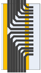
Top feed
Bottom feed
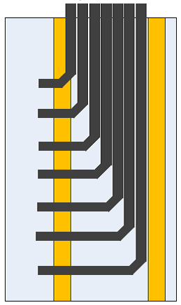
Top/bottom feed
Bundles should always be plugged in from bottom to top. This is because when plugged in from top to bottom, the top cables will slow down plugging the next bundle under.
Additionally, as was detailed in Section 4.1.1, cables and thus bundles destined for the same switch at the same U must be split in a 50/50 manner. This allows half the cables to be routed along the left side of the rack and half the cables along the right and then to their destination port. This division allows the great volume of the many InfiniBand cables to be balanced equally and thus reduces the total number of cables on any one side of the rack. Additionally, it allows for greater serviceability of all equipment within the rack ensuring no cable passes the midpoint of the rack impeding the insertion or removal of equipment (Figure 34).
Figure 34. Top view of cables on the connector side
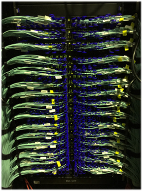
Figure 35 shows a front view of a properly cabled chassis-based switch.
Figure 35. Front view chassis-based switch
Install#
Good cabling begins with good preparation. In previous steps, the environment and cable management have been surveyed for readiness. The cables are, by this point, labeled and bundled and thus are ready to be laid in their final position.
Typically, the BSN will be sequential and reflect the order in which to deploy the bundles. However, this is not always true, therefore it is recommended to first consult the cable deployment documentation to determine the order in which the bundles are to be deployed. In general, the inter-rack cable bundles will be run first, and the intra-rack cable bundles run last.
Installing the inter-rack cable bundles#
Even the best cable management infrastructure can have obstructions that prevent directly placing the bundle within. It will therefore in some cases be necessary to coil the bundle as a whole and unroll it as it is placed in its final location.
Note
The cable bundles must be supported in some fashion while being placed into the cable management. This may entail temporary wrappings and strappings or any supporting methods to ensure that the bundle does not kink or stretch while being worked with.
Note
Slack should be positioned nearer the TOR switches. The core and intermediate/aggregate switches will have numerous cables running to them and therefore slack above these will cause congestion within the cable management.
Note
Never route cables through the middle of the rack. This results in air flow restrictions and makes servicing all equipment blocked by the cables difficult or impossible without disconnecting the cables.
Move the prepared cable bundles from the staging area to the area immediately near, in front of, the core switch/network rack and the bundle deployment.
Place the first eight feet or so of the cable bundle into the cable management +/- a rough estimate of the required free cable to reach the U for which it is destined.
Carefully fish the free cable through the designated cable openings and ensure that the connectors will reach the midpoint of the switch or line card.
Do not connect the cable yet. Tie this end in place with hook-and-loop and continue with the bundle.
Moving down the length of the bundle place it into the cable management, carefully working around support structures, when making corners take the widest radius possible.
Upon reaching the destination rack, review the remaining length of the bundle and if considerable slack is present determine the best manner to address:
Cable management comes in different sizes and ideally it was sized large enough to contain cable slack.
Cable slack is best managed by creating large loops with large bend radius that double back on themselves.
As with the first end of the bundle, carefully fish the free cable through the designated cable openings and ensure that the connectors will reach the midpoint of the switch or line card.
Do not connect the cable yet. Tie this end in place with hook-and-loop and continue with the bundle.
Repeat this process for the remaining bundles.
Continue to Connecting and Dressing Cables/Bundles and then return to the next section.
Installing the intra-rack cable bundles
Cable management within a rack takes many forms. The key items to keep in mind are bend radius, cable support, and individual cable path management. Cable bend radius should never at any time exceed specifications. Proper cable support should be implemented to ensure longevity. Once cables are separated from the bundle, they must be managed to prevent the blocking of other equipment, restricting air flow, and maintaining equipment serviceability.
Shape
Description automatically generated with low confidence
Warning: Never route cables through the middle of the rack. This results in air flow restrictions and makes servicing equipment blocked by the cables difficult or impossible without disconnecting the cables.
Generally, intra-rack cabling is not bundled before installation and given the variables of rack cable management it must be left to the installer to determine whether to begin at the switch end of the cable or node end.
Whether starting at the switch or node plug the connector into its source port and fish the cable to the destination port, taking special care not to twist the cable near the connector.
Note: If it is necessary to reorient the connector, begin the adjustment further down the cable, at least 75 cm away from the connector, so the twist occurs gradually along the cable instead of abruptly near the connector.
Use the cable management to orderly contain any slack, maintaining awareness of bend radius limitations.
Repeat this process for the remaining bundles.
Continue to Connecting and Dressing Cables/Bundles with attention paid to dressing.
Connecting and Dressing Cables/Bundles#
Connecting and dressing cables/bundles are discussed together to ensure a clean appearance and an easily maintained deployment. Both must occur concurrently. Simply plugging the connectors in and running to the side will result in tangles and disorder that will progressively worsen as the number of cables increases.
Note
Be sure to provide strain relief, cables must be supported to prevent stress. In general, a cable should be supported at least every two feet (60 cm).
Warning
Straps must not be so tight as to distort the jacket of the cable. They are only used to prevent unnecessary movement of the cable; snug is tight enough.
Connecting#
Work on the left side or the right side of the rack first.
Begin by removing any plastic wrap that was used during the installation process. Additionally, remove any protective caps that might remain on the cable.
If cables enter through the top of the rack, begin with bundles with destinations at the top.
Using the label information, fully seat the connector into the correct port. It is possible that other cables may need to be unplugged and plugged back in again to avoid tangles and resolve twists caused by the cable wanting to return to its original coiled shape.
Because cables routed to the left or right most ports will be shorter than those to the middle variations will result in slack, route this into the in rack cable management.
Progress one U at a time and alternate between connecting ports and dressing cables.
Continue to the next section.
Dressing for Equipment#
Having connected all the cables for the left or right side of a single U, begin near the middle and gently guide the cables into shape.
Be careful with bend radiuses, and do not pull on cables.
Keep the plane of the cables in line with the level of the U that they connect to.
Using hook-and-loop, wrap at intermediate points and then within the cable management.
In the early stages of the connection dressing process, keep the wraps quite loose as they may need to be adjusted.
Once reaching the last cable, add extra wraps as needed to any slack, wraps, or bends.
When everything looks right, tighten any wraps to just snug, and then close-up any cable management.