Ethernet Switch Ports#
Ethernet Switch Ports
Ethernet switches, especially top of rack (ToR) switches, often must support a variety of link speeds on the same switch, for example, 200 GbE uplinks with a mix of 50 GbE and 10 GbE downlinks within the rack. A variety of cable types is required to provide this flexibility.
Mixing Port Speeds#
Enabling the necessary mix of uplinks and downlinks, including backwards compatibility to previous Ethernet generations, involves a combination of per-port speeds and port splitting. Switch vendors try to simplify this by offering models with different mixes of port speeds, but cables provide another layer of customization. For example, if a customer still has a few legacy GbE-connected nodes it may make sense to connect them to 10 GbE-capable ports instead of keeping the legacy GbE switches.
Tailoring switch port speed depends on:
Native capabilities of the switch hardware, and switch vendor feature decisions
Fundamental ‘link format’ considerations: lane rates and number of lanes
The following discussion deals with the fundamentals, which may be further restricted by a given switch model.
Table 3 showed the fundamental properties of each Ethernet speed class and how its aggregate throughput maps to a physical link. Often it is also possible to reduce a port’s lane rate for backwards compatibility, for example to use a 100 GbE-capable port for 40 GbE, but all lanes of the port must run at the same rate.
Splitting Switch Ports#
For multilane ports, it is often possible to logically split the lanes into subsets and use a physical splitter (breakout) cable.
Each ‘leg’ of a splitter must conform to a row in Table 3. For example, it is not possible to derive a 4 GbE link by running a 100 GbE port’s lanes at 1 Gbps, nor is it possible to create a 20 GbE link by running a 50 GbE (2x25) port at 10 Gbps per lane. Some legacy implementations cannot be accommodated, for example 100 GbE using 10 lanes of 10 Gbps each.
Splitter Cables#
Table 4 shows the valid combinations of splitters and lane rates.
Switch Port (GbE) |
Lanes |
Switch Connector |
Port Mode |
Lanes per Split |
Rates per Lane (GbE) |
|||
|---|---|---|---|---|---|---|---|---|
50 |
25 |
10 |
1 |
|||||
10 |
1 |
SFP+ |
Unsplit |
1 |
10³ |
1³ |
||
25 |
1 |
SFP28 |
Unsplit |
1 |
25³ |
10³ |
1³ |
|
40 |
4 |
QSFP |
Unsplit |
4 |
40 |
|||
4-way |
1 |
4x10³ |
4x1³ |
|||||
50 |
2 |
QSFP28 |
Unsplit |
2 |
50 (2x25) |
|||
1 |
SFP56 |
Unsplit |
1 |
50³ |
||||
100 |
4 |
QSFP28 |
Unsplit |
4 |
100 |
40 |
||
2-way |
2 |
2x501 |
||||||
4-way |
1 |
4x25³ |
4x10³ |
4x1³ |
||||
200 |
4 |
QSFP56 |
Unsplit |
4 |
200 |
100 |
40 |
|
2-way |
2 |
2x100² |
2x50¹ |
|||||
4-way |
1 |
4x50³ |
4x25³ |
4x10³ |
4x1³ |
|||
¹. Each leg is two lanes of 25 Gbps (2x25) ². Each leg is two lanes of 50 Gbps (2x50) ³. SFP+/SFP28/SFP56 as appropriate |
||||||||
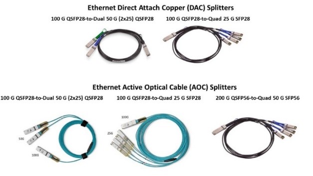
For example, a quad splitter for a 100 GbE port can provide four links of 25 GbE, 10 GbE, or 1 GbE and will have a QSFP on the port end and SFP connectors on the other four legs. Again, specific switch models may not support all combinations shown. Several examples of Ethernet splitter cables are shown in Figure 28.
Figure 28. Examples of Ethernet splitter cables
Connecting SFP to QSFP#
If two ports must be connected but one is SFP and one is QSFP, for example to connect a 25 GbE HCA to a QSFP port capable of both 100 GbE and 25 GbE, there are three solutions:
Use a four-way splitter and do not use three of its legs.
Hybrid cables.
QSFP to SFP Adapters (QSAs).
A hybrid cable has a male SFP connector on one end and a male QSFP connector on the other. One specific lane from the QSFP side is connected to the single lane of the SFP. Though technically simple, there are practical issues:
Multiple lengths are needed, with a mix of copper and optical versions.
Signal integrity must match the application. For example, a hybrid DAC cable designed for 10 GbE will be constructed differently than a 25 GbE DAC.
To simplify connections between QSFP and SFP ports, NVIDIA introduced the QSA in 2011.
Quad to Single Adapters (QSAs)#
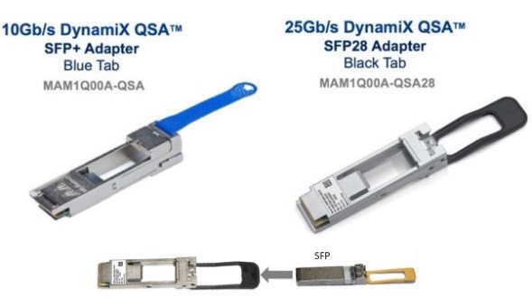
A QSA is a simple passive module with a QSFP male connector on the port side and an SFP female connector on the other. It resembles a transceiver but is essentially a zero-length hybrid cable that needs no port power. Any compatible standard cable can then be used to complete the link. Examples of QSA modules are shown in Figure 29.
Figure 29. QSFP to SFP (QSA) adapters
To optimize cost based on speed and thermal requirements, there are multiple QSA types:
40 GbE to 10 GbE.
100 GbE to 25 GbE.
200 GbE to 50 GbE.
Extended temperature versions for hotter environments.
Ethernet Transceivers#
Transceiver costs, and power drawn from an Ethernet port, are a function of speed and distance (reach).