Network Fabrics#
Building systems by SU provides the most efficient designs. However, if a different node count is required due to budgetary constraints, data center constraints, or other needs, the fabric should be designed to support the full SU, including leaf switches and leaf-spine cables, and leave the portion of the fabric unused where these nodes would be located. This will ensure optimal traffic routing and ensure that performance is consistent across all portions of the fabric.
DGX SuperPOD configurations utilize five network fabrics:
NVLink 5
Compute Fabric
Storage Fabric
In-Band Management Network
Out-of-Band Management Network
These network segments are carried by four different physical fabrics:
Multi-node NVLink Fabric (MN-NVL)
Compute InfiniBand Fabric
Storage and In-band Ethernet Fabric
Out-of-Band network
Each of these fabrics are discussed in this section.
Multi-node NVLink Fabric (NVL5)#
Each DGX GB200 rack is built with 18 compute trays and 9 NVLink switch trays. Each NVLink switch tray is equipped with 2 NVLink switch chips and are responsible for the full-mesh connectivity between all 72 GPUs within the same DGX GB200 rack. Each B200 GPU features 18 NVL5 links and has one dedicated NVL5 link connectivity to each one of the 18 switch chips, delivering a total bandwidth of 1.8 TB/s low latency bandwidth.
Note
Each network is detailed in this section.
Figure 8 shows the ports on the back of the DGX B200 CPU tray and the connectivity provided. The compute fabric ports in the middle use a two-port transceiver to access all eight GPUs. Each pair of in-band management and storage ports provide parallel pathways into the DGX B200 ystem for increased performance. The OOB port is used for BMC access. (The LAN port next to the BMC port is not used in DGX SuperPOD configurations.)
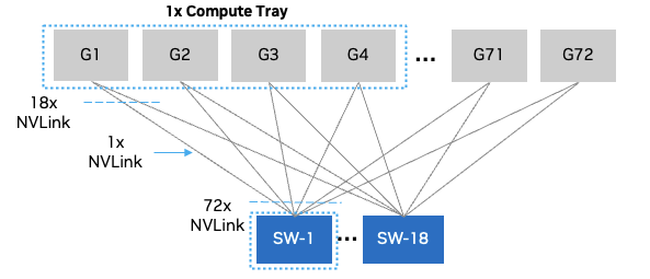
Figure 8 Multi-node NVLink Topology#
Compute Fabric#
Figure 9 shows the compute fabric layout for the full GB200 SuperPOD Scalable Unit (8 DGX GB200 systems). Each compute rack is rail-aligned. Traffic per rail of each compute tray is always one hop away from other compute trays in the same Scalable Unit. Traffic between different compute racks, or between different rails, traverses the spine layer.
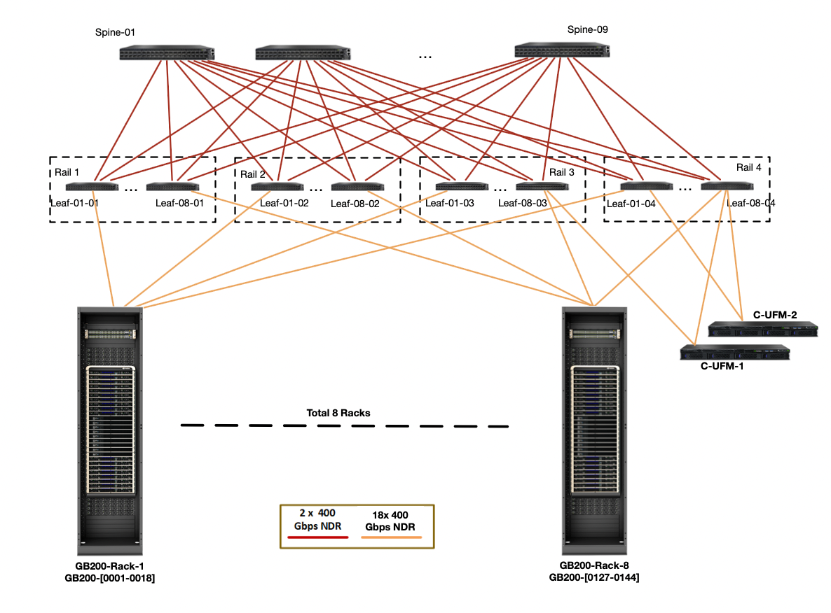
Figure 9 Compute fabric for full 576 GPUs DGX SuperPOD#
For designs larger than one SU, we provide spine-leaf-group (SLG) based scalable design with scalability for up to and including 16 SUs. Each SU contains 4 SLGs to match with the number of IB rails (which equals the number of GPUs per compute tray). There are 8 leaf switches (one for each compute rack) and 6 spine switches in each SLG – allowing a fully non-blocking fat tree topology for each SU to be attached to 6 core groups. The details of this design for scale-out is presented in Figure 10. Table 3 shows an outline for the switches required for scale out build of DGX SuperPOD.
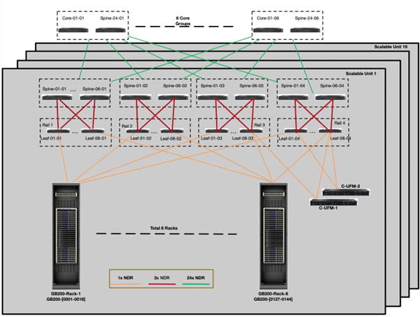
Figure 10 Compute Fabric for Scale Out of up to 16 SUs#
# GPUs |
# SUs |
# Core Group |
Switch per Core Group |
Core Switch |
IB Leaf Switch |
IB Spine Switch |
||
|---|---|---|---|---|---|---|---|---|
Per SU |
Total |
Per SU |
Total |
|||||
1152 |
2 |
6 |
3 |
18 |
32 |
64 |
24 |
48 |
2304 |
4 |
6 |
6 |
36 |
32 |
128 |
24 |
96 |
4608 |
8 |
6 |
12 |
72 |
32 |
256 |
24 |
192 |
9216 |
16 |
6 |
24 |
144 |
32 |
512 |
24 |
384 |
Storage and In-band Ethernet Fabric#
With DGX GB200, we introduced a new generation of ethernet-based fabric for storage and in-band network to enhance cost-efficiency while maintaining the high level of performance required by the storage network in a large-scale AI training cluster.
The storage and in-band fabric use SN5600 switches and SN2201 switches shown in Figure 11 and Figure 12 respectively.
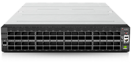
Figure 11 SN5600 Switch#
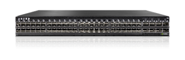
Figure 12 SN2201 Switch#
Figure 13 shows the physical layout of a single SU. Figure 12 shows the physical layout of a single SU. Each SU features two SN5600 switches as the aggregation layer or spine layer for the physical network. Here – all the leaf level switches facing DGX, Storage, and the out-of-band connection are aggregated on these pair of switches. On the leaf layer, DGX compute trays are connected at 4x 200GbE on their BlueField 3 DPUs. One additional pair of SN5600 switches serves as the ingestion point for Storage Appliances and control plane nodes. One additional pair of SN2201 switches are to connect all legacy devices requiring RJ45 connections or QSFP based uplink connectivity.
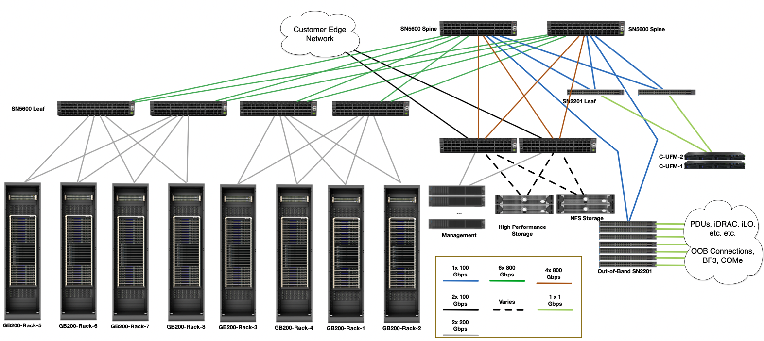
Figure 13 Storage and In-band Ethernet fabric logical design#
To achieve desired scale-out to up to and including 16 SUs, a third layer of switches – known as super spine – are added. Figure 14 shows the scale-out design for SuperPOD. Similar to the compute fabric, each SU in the SuperPOD can be implemented incrementally – given the super spine layer is built to support the maximum number of spine switches in the SuperPOD. The super spine is designed with 2 groups. Each Spine is expected to have 28x 800GbE connection uplinks to maintain non-blocking characteristics for the disaggregated storage design in the scalable SuperPOD reference architecture.
Figure 14 shows this design for scale out and Table 4 summarize the required number of switches for example size of SUs.
# GPUs |
# SUs |
# Super Spine Groups |
Super Spines per Group |
# Super Spine Switches |
# Spine Switches |
IB Spine Switch |
||
|---|---|---|---|---|---|---|---|---|
4 |
Total |
Per SU |
Total |
|||||
2304 |
4 |
2 |
2 |
4 |
8 |
64 |
24 |
48 |
4608 |
8 |
2 |
4 |
8 |
16 |
128 |
24 |
96 |
9216 |
16 |
2 |
7 |
14 |
32 |
256 |
24 |
192 |
9216 |
16 |
6 |
24 |
144 |
32 |
512 |
24 |
384 |
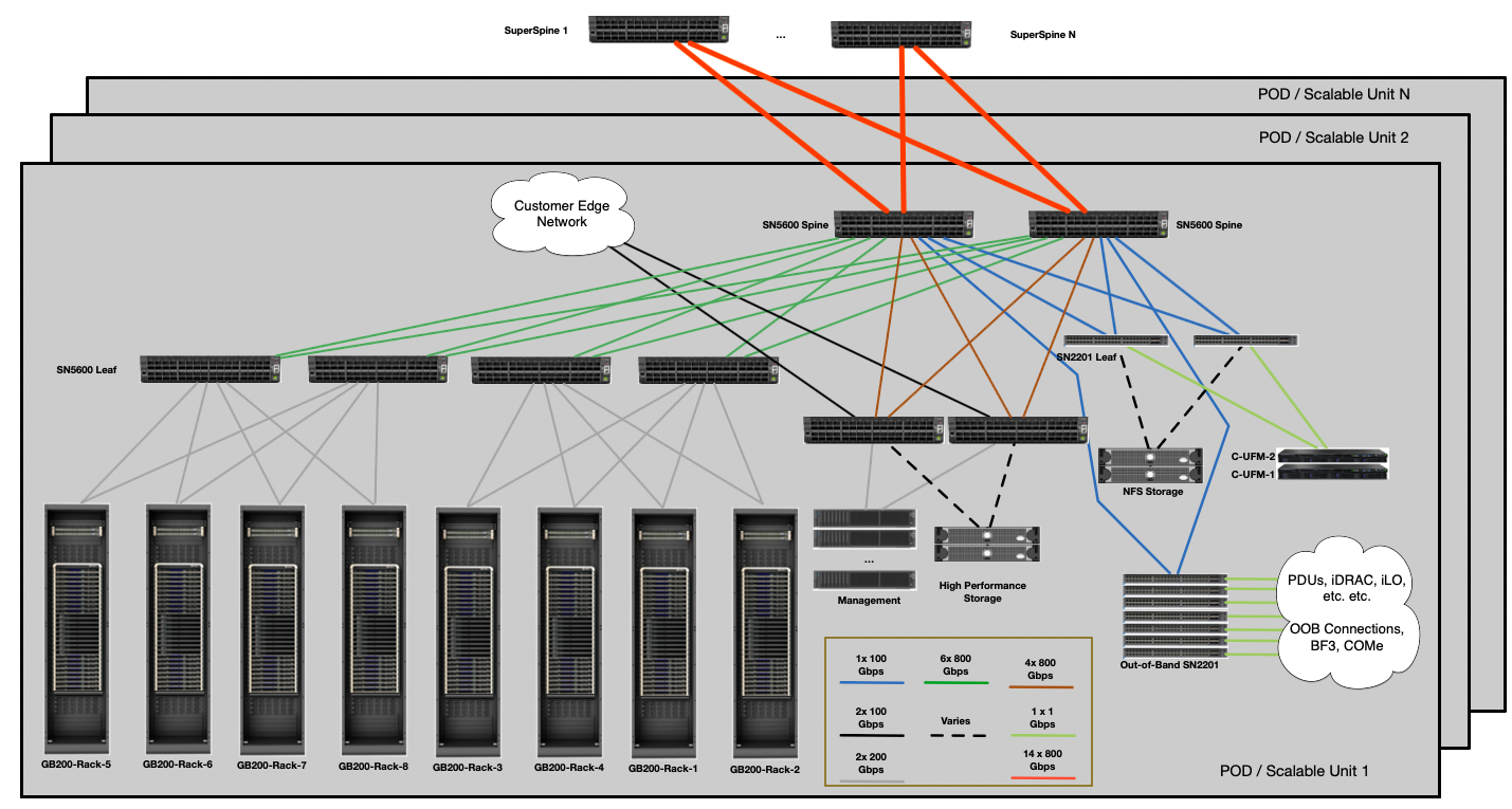
Figure 14 Storage and In-band Ethernet fabric scale out#
Network Segmentation of the Ethernet Fabric#
The ethernet fabric is segmented into these segments on the SuperPOD:
Storage Network
In-band Network
Out-of-Band Management Network
In the following, we introduce these networks in detail.
Storage Network#
The storage network embodies the performance for the high-speed storage while keeping the support for high availability. To achieve this, 2 out of the 4 available ports on each BlueField-3 DPU are dedicated for storage access.
The physical ethernet fabric carries a dedicated VXLAN with termination points on the leaf switches for the DGX nodes’ storage NIC ends on each SN5600 Leaf switches. In addition, one pair of SN5600 leaf in each SU provides the connectivity to the storage appliances. RoCE is a basic requirement for the storage appliances, which benefits from advanced fabric management features, such as congestion control and AR (Adaptive Routing), provides lower latency while maintaining the high bandwidth requirement.
Each scalable unit is designed to carry 16x 800Gbps non-blocking bandwidth to the storage appliances. On the DGX node side, each scalable unit carries a slightly blocking fabric with a blocking factor of 5:3. Figure 15 shows the logical view of the storage fabric.
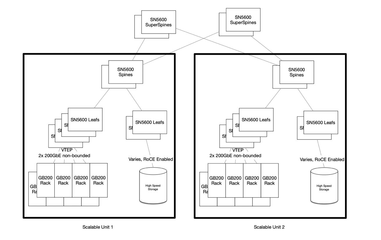
Figure 15 Storage Fabric Underlay Network#
In-Band Management Network#
The in-band management network provides several key functions:
Connects all the services that manage the cluster.
Enables access to the lower-speed, NFS tier of storage.
Provides uplink (border) connectivity for the in-cluster services such as Mission Control, Base Command Manager, Slurm, and Kubernetes to other services outside of the cluster such as the NGC registry, code repositories, and data sources.
Provides end user access to the Slurm head nodes and Kubernetes services.
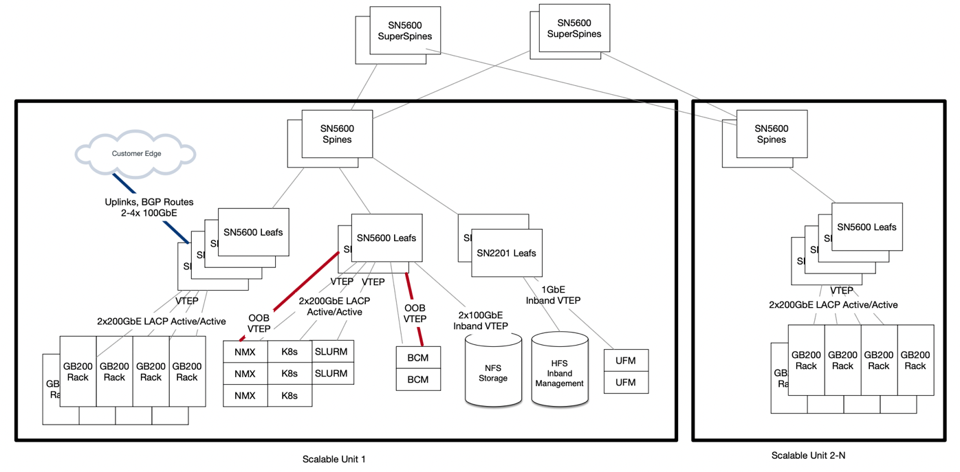
Figure 16 In-band Fabric Underlay Network#
The in-band network itself is split into 3 different segments:
A dedicated VTEP for uplink, the default hand over to customer edge is based on BGP peering and providing routes from in-band (and leaked routes from OOB) to customers’ edge.
Customer is also expected to provide link to the building management system network (BMS) as part of their edge connectivity.
A dedicated VTEP for out-of-band network for the network management devices (NMX-Manager) and for BCM to access the telemetry and perform management functions to the OOB devices.
The in-band VTEP, which carries the network for user access, home-directory storage access via NFS, service delivery, and general control traffic.
Out-of-Band Management Network#
Figure 17 shows the OOB Ethernet fabric. It connects the management ports of all devices including DGX GB200 compute trays, switch trays, and management servers, storage, networking gear, rack PDUs, and all other devices. These are separated onto their own network. There is no use-case where a non-privileged user needs direct access to these ports and are secured using logical network separation.
The OOB network carries all IPMI related control traffic and serves as the network for fabric management of the compute InfiniBand fabric and compute NVLink fabric.
The OOB network is physically rolled up into the aggregation layer (spine layer) of each SU as a dedicated VXLAN. The OOB management network use SN2201 switches, shown in Figure 18
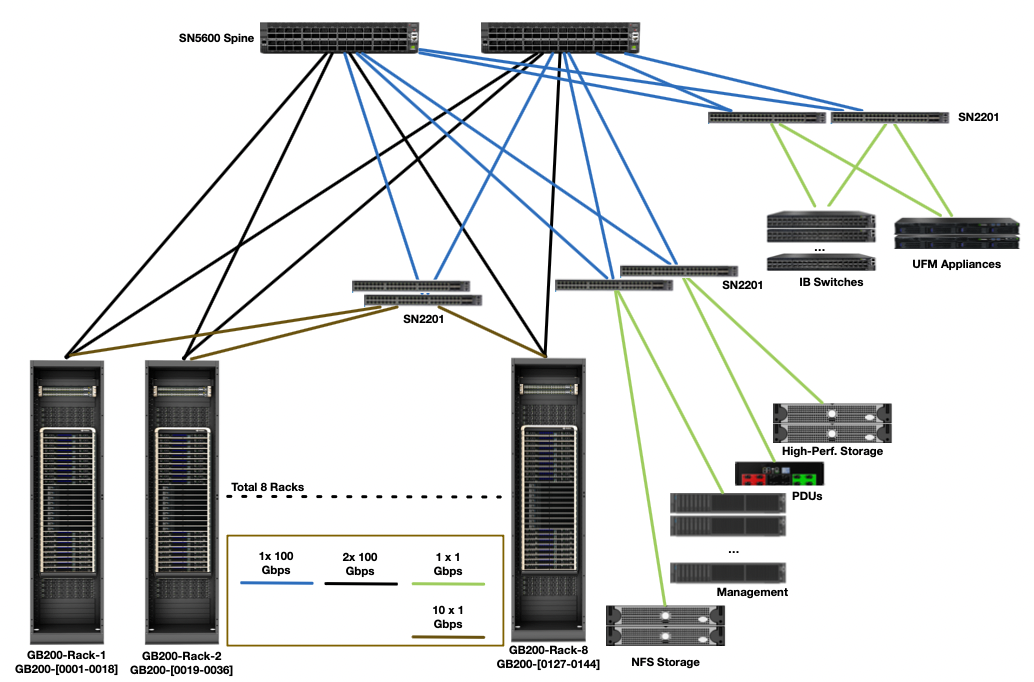
Figure 17 Logical OOB management network layout#
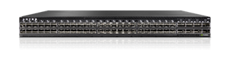
Figure 18 SN2201 switch#
Customer Edge Connectivity#
For connecting DGX SuperPOD to customer edge for uplink and customer corporate network access, we recommend at least 2x 100GbE links with DR1 single-mode connectivity to cope with the growing demand on high-speed data transfer into and from DGX SuperPOD.
A new introduction to DGX SuperPOD with DGX GB200 systems because of its complex cooling and power requirement is the connection to the Building Management System (BMS). The BMS serves is the management plane of the operational technology (OT) side of the data center infrastructure.
For route handover, we prepare eBGP protocol to peer with customer’s network. Routes to/from in-band, out-of-band, and building management system are announced. Figure 19 shows an example for customer edge connectivity.
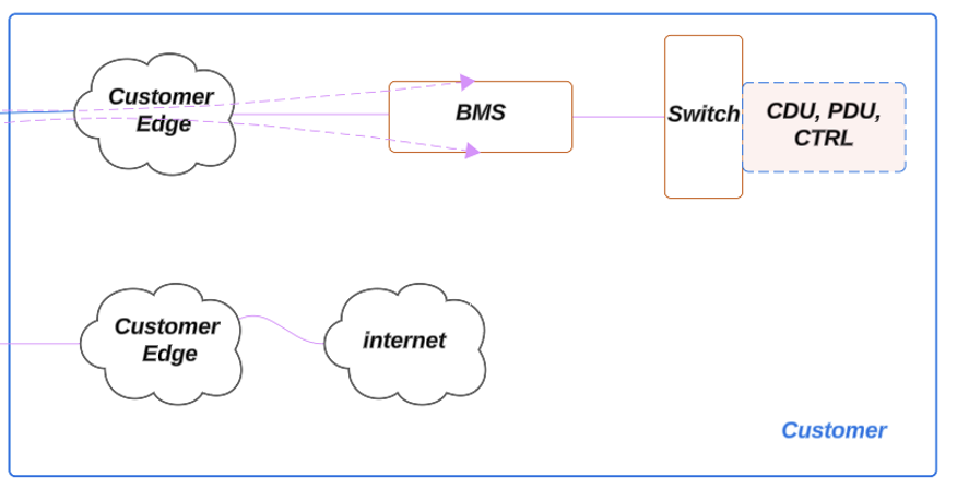
Figure 19 Example Customer Edge Connectivity#