Introduction to NVIDIA DGX B200 Systems#
The NVIDIA DGX™ B200 System is the universal system purpose-built for all AI infrastructure and workloads from analytics to training to inference. The system is built on eight NVIDIA B200 Tensor Core GPUs.
Hardware Overview#
DGX B200 Component Descriptions#
The NVIDIA DGX B200 (1,440 GB) system includes the following components.
Component |
Description |
|---|---|
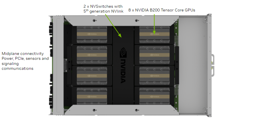
GPU |
8 x NVIDIA B200 GPUs that provide 1,440 GB total GPU memory |
CPU |
2 x Intel Xeon 8570 PCIe Gen5 CPUs with 56 cores each 2.1/4 GHz (Base/Max boost) |
NVSwitch |
2 x 5th generation NVLink switches that provide 14.4 TB/s aggregate bandwidth |
Storage (OS) |
2 x 1.92 TB NVMe M.2 SSD (ea) in RAID 1 array |
Storage (Data Cache) |
8 x 3.84 TB NVMe U.2 SED (ea) in RAID 0 array |
Network (Cluster) card |
4 x OSFP ports for 8 x NVIDIA® ConnectX®-7 Single Port Cards Each card provides the following speeds:
|
Network (storage and in-band management) card |
2 x NVIDIA® BlueField®-3 DPU Dual Port Cards Each card provides the following speeds:
|
System memory (DIMM) |
2 TB using 32 x DIMMs (upgradable to 4 TB) |
BMC (out-of-band system management) |
1 GbE RJ45 interface Supports Redfish, IPMI, SNMP, KVM, and Web user interface |
System management interfaces (optional) |
Dual port 100GbE in slot 3 and 10 GbE RJ45 interface |
Power supply |
6 x 3.3 kW |
Mechanical Specifications#
Feature |
Description |
|---|---|
Form Factor |
10U Rackmount |
Height |
17.5” (444 mm) |
Width |
19” (482.3 mm) max |
Depth |
35.3” (897.1 mm) max |
System Weight |
313.9 lbs (142.4 kg) max |
Power Specifications#
The DGX B200 system contains six power supplies with a balanced distribution of the power load.
Input |
Specification for Each Power Supply |
|
|---|---|---|
200-240 volts AC |
14.3 kW max. |
3,300 W @ 200-240 V, 16 A, 50-60 Hz |
Support for PSU Redundancy and Continuous Operation#
The system includes six power supply units (PSU) configured for 5+1 redundancy.
Refer to the following additional considerations:
If a PSU fails, troubleshoot the cause and replace the failed PSU immediately.
If two PSUs lose power due to a data center issue or power distribution unit failure, the system continues to function but at a reduced performance level.
If only two PSUs have power, shut down the system before replacing an operational PSU.
The system only boots if at least three PSUs are operational. If fewer than three are operational, only the BMC is available.
Do not operate the system with PSUs depopulated.
This table shows the effects of disconnecting AC power cables from the DGX B200 system.
AC Power Cable
Disconnection
|
Operating PSUs
|
Effect
|
Maximum Power
per GPU [1]
|
|---|---|---|---|
Removing 1 cable |
5 |
No effect on the DGX system. |
1,000 W |
Removing 2 cables |
4 |
The BMC alerts on AC power loss. |
800 W |
Removing 3 cables |
3 |
The BMC alerts on AC power loss. |
800 W |
Removing 4 cables |
2 |
The DGX system shuts down. |
Not applicable |
DGX B200 Locking Power Cord Specification#
The DGX B200 system is shipped with a set of six (6) locking power cords that have been qualified for use with the DGX B200 system to ensure regulatory compliance.
Warning
To avoid electric shock or fire, only use the NVIDIA-provided power cords to connect power to the DGX B200. For more information, refer to Electrical Precautions.
Important
Do not use the provided cables with any other product or for any other purpose.
Power Cord Specification
Power Cord Feature |
Specification |
|---|---|
Electrical |
250VAC, 20A |
Plug Standard |
C19/C20 |
Dimension |
1200mm length |
Compliance |
Cord: UL62, IEC60227 Connector/Plug: IEC60320-1 |
Using the Locking Power Cords#
This section provides information about how to use the locking power cords.
Locking and Unlocking the PDU Side
Power Distribution Unit side
To INSERT, push the cable into the PDU socket.
To REMOVE, press the clips together and pull the cord out of the socket.
Locking/Unlocking the PSU Side (Cords with Twist-Lock Mechanism)
Power Supply (System) side - Twist locking
To INSERT or REMOVE, ensure the cable is UNLOCKED and push/ pull into/out of the socket.

Environmental Specifications#
Here are the environmental specifications for your DGX B200 system.
Feature |
Specification |
|---|---|
Operating Temperature |
10°C to 35°C (50˚F to 95˚F) |
Relative Humidity |
20% to 80% non-condensing |
Airflow |
1,550 CFM |
Heat Output |
48,794 BTU/hr |
Front Panel Connections and Controls#
This section provides information about the front panel, connections, and controls of the DGX B200 system.
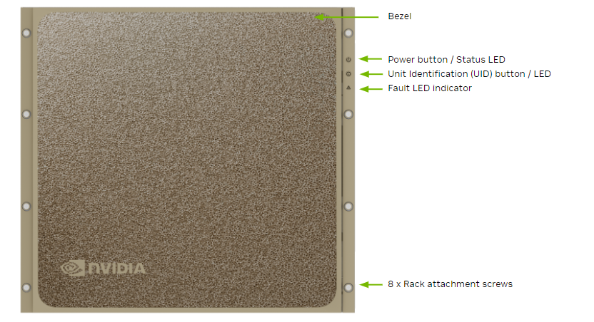
With a Bezel#
Here is an image of the DGX B200 system with a bezel.
Control |
Description |
|---|---|
Power Button |
Press to turn the DGX B200 system on or off.
|
ID Button |
Press to have the blue LED turn On or blink (configurable through the BMC) as an identifier during servicing. It also causes an LED on the back of the unit to flash as an identifier during servicing. |
Fault LED |
Amber On: System or component faulted |
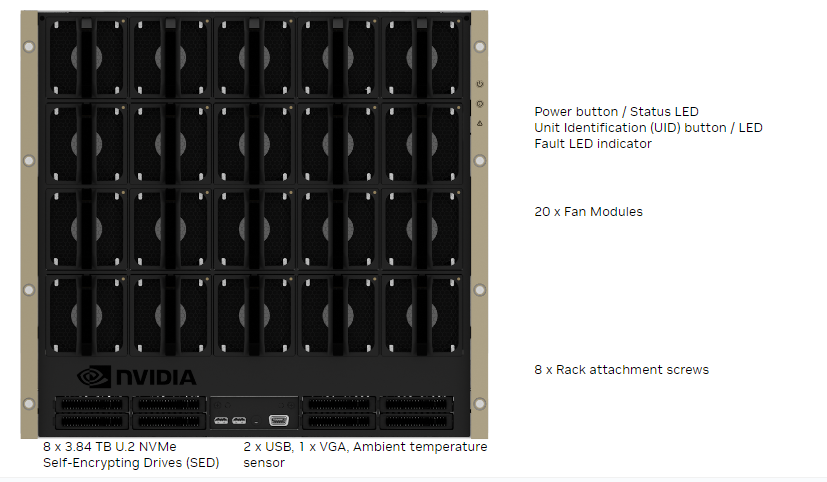
With the Bezel Removed#
Here is an image of the DGX B200 system without a bezel.
Important
Refer to the section First Boot Setup for instructions on how to properly turn the system on or off.
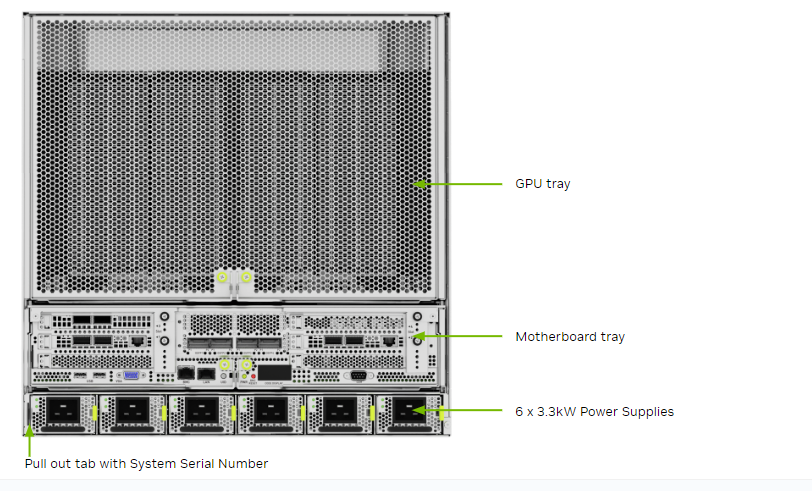
Rear Panel Modules#
Here is an image that shows the actual panel modules on DGX B200.
Motherboard Connections and Controls#
The following image shows the motherboard connections and controls in a DGX B200 system.
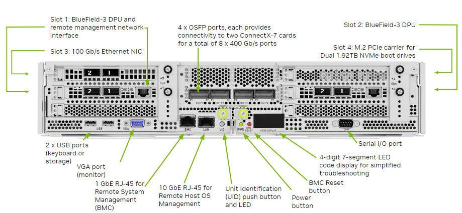
Control |
Description |
|---|---|
Power Button |
Press to turn the system On or Off. |
ID LED Button |
It blinks when the ID button is pressed from the front of the unit to help identify the unit that needs servicing. |
BMC Reset Button |
Press to manually reset the BMC. |
See Network Connections, Cables, and Adaptors for details on the network connections.
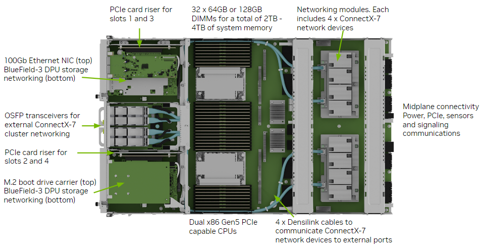
Motherboard Tray Components#
The following image shows the motherboard tray components in the DGX B200 system.
GPU Tray Components#
Here is an image of the GPU tray components in the DGX B200 system.
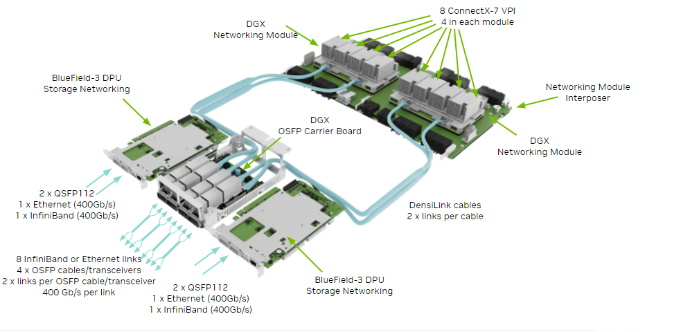
Network Connections, Cables, and Adaptors#
This section provides information about network connections, cables, and adaptors.
Network Ports#
Here is an image that shows the network ports on a DGX B200 system.
Port Designation |
||||
|---|---|---|---|---|
Port |
PCI Bus |
Default |
Optional |
RDMA |
OSFP1P1 |
dc:00.0 |
ibp220s0 |
enp220s0np0 |
mlx5_15 |
OSFP1P2 |
9a:00.0 |
ibp154s0 |
enp154s0np0 |
mlx5_10 |
OSFP2P1 |
ce:00.0 |
ibp206s0 |
enp206s0np0 |
mlx5_14 |
OSFP2P2 |
c0:00.0 |
ibp192s0 |
enp192s0np0 |
mlx5_13 |
OSFP3P1 |
4f:00.0 |
ibp79s0 |
enp79s0np0 |
mlx5_8 |
OSFP3P2 |
40:00.0 |
ibp64s0 |
enp64s0np0 |
mlx5_7 |
OSFP4P1 |
5e:00.0 |
ibp94s0 |
enp94s0np0 |
mlx5_9 |
OSFP4P2 |
18:00.0 |
ibp24s0 |
enp24s0np0 |
mlx5_4 |
Slot1 P1 |
aa:00.0 |
ibp170s0f0 |
enp170s0f0np0 |
mlx5_11 |
Slot1 P2 |
aa:00.1 |
enp170s0f1np1 |
ibp170s0f1 |
mlx5_12 |
Slot2 P1 |
29:00.0 |
ibp41s0f0 |
enp41s0f0np0 |
mlx5_5 |
Slot2 P2 |
29:00.1 |
enp41s0f1np1 |
ibp41s0f1 |
mlx5_6 |
Slot3 P1 |
82:00.0 |
ens6f0 |
N/A |
irdma0 |
Slot3 P2 |
82:00.1 |
ens6f1 |
N/A |
irdma1 |
On-board |
0b:00.0 |
eno3 |
N/A |
|
Compute and Storage Networking#
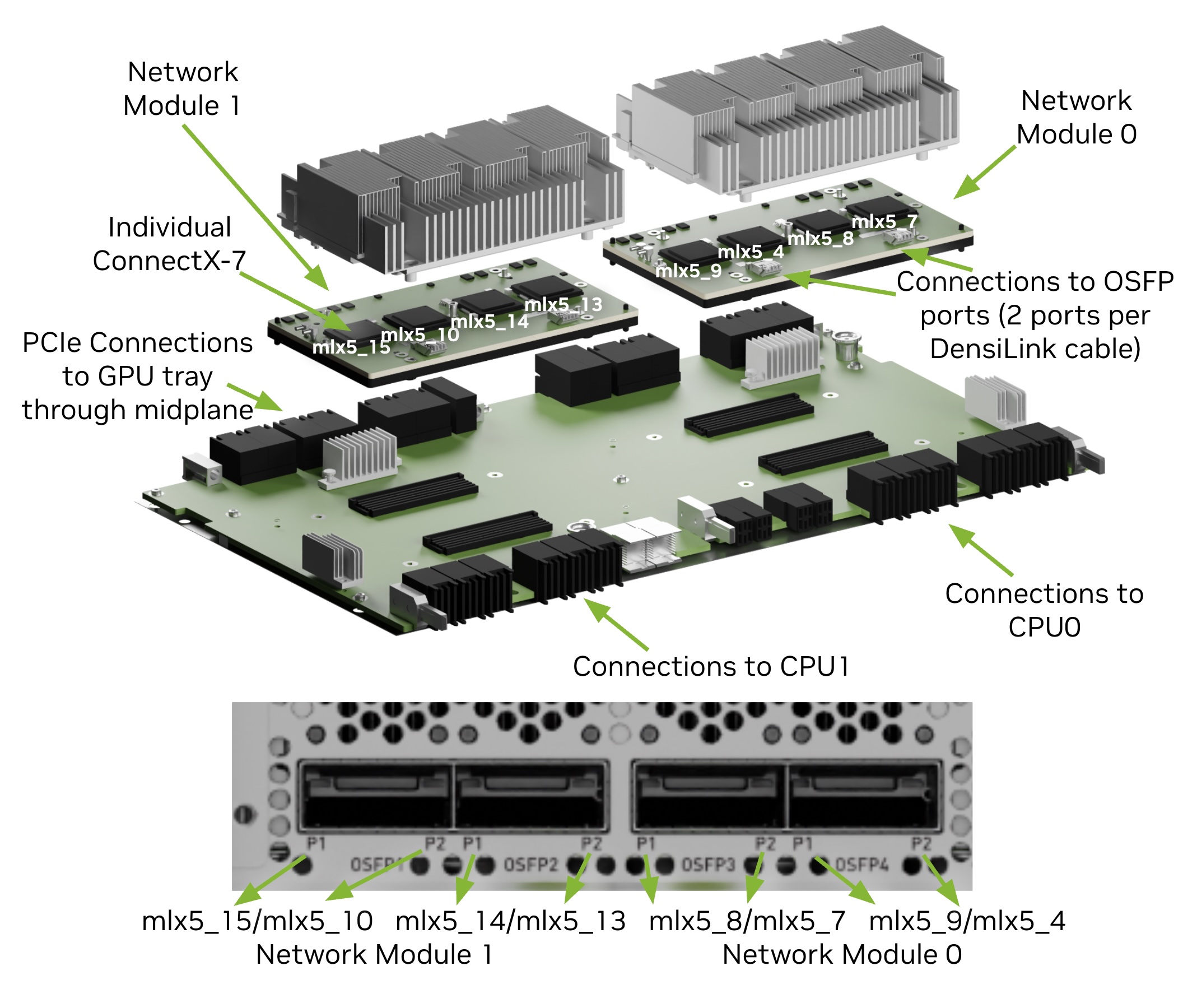
Network Modules#
New form factor for aggregate PCIe network devices
Consolidates four ConnectX-7 networking cards into a single device
The DGX B200 system has eight ConnectX-7 network cards on two network module trays. Internal DensiLink cables connect the dual-port OSFP interface to the individual ConnectX-7 network card.
Port |
ConnectX Device |
Network Module/CPU |
GPU |
Default |
RDMA |
|---|---|---|---|---|---|
OSFP1P1 |
CX0 |
1 |
7 |
ibp220s0 |
mlx5_15 |
OSFP1P2 |
CX1 |
1 |
4 |
ibp154s0 |
mlx5_10 |
OSFP2P1 |
CX2 |
1 |
6 |
ibp206s0 |
mlx5_14 |
OSFP2P2 |
CX3 |
1 |
5 |
ibp192s0 |
mlx5_13 |
OSFP3P1 |
CX2 |
0 |
2 |
ibp79s0 |
mlx5_8 |
OSFP3P2 |
CX3 |
0 |
1 |
ibp64s0 |
mlx5_7 |
OSFP4P1 |
CX0 |
0 |
3 |
ibp94s0 |
mlx5_9 |
OSFP4P2 |
CX1 |
0 |
0 |
ibp24s0 |
mlx5_4 |
BMC Port LEDs#
The BCM RJ-45 port has two LEDs.
The LED on the left indicates the speed. Solid green indicates the speed is 100M. Solid amber indicates the speed is 1G.
The LED on the right is green and flashes to indicate activity.
Supported Network Cables and Adaptors#
The DGX B200 system is not shipped with network cables or adaptors. You will need to purchase supported cables or adaptors for your network.
The ConnectX-7 firmware determines which cables and adaptors are supported. For a list of cables and adaptors compatible with the NVIDIA ConnectX cards installed in the DGX B200 system,
Visit the NVIDIA Adapter Firmware Release page.
Click the ConnectX model and select the corresponding firmware included in the DGX B200 system.
From the left Topics pane, select the Validated and Supported Cables and Switches topic.
To configure the BlueField-3 DPU in NIC mode, follow the instructions in NIC Mode for BlueField-3.
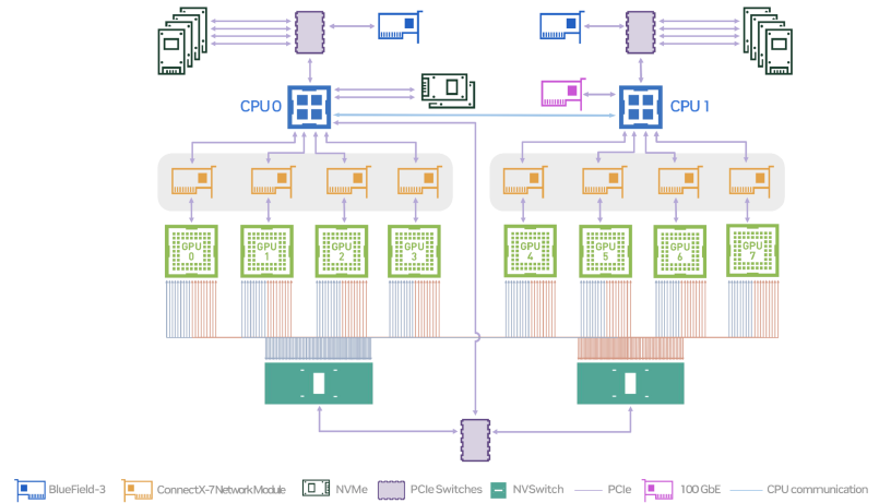
DGX B200 System Topology#
The following figure shows the DGX B200 system topology.
DGX OS Software#
The DGX B200 system comes pre-installed with a DGX software stack incorporating the following components:
An Ubuntu server distribution using the optimized Linux kernel with supporting packages
The following system management and monitoring software:
NVIDIA System Management (NVSM)
Provides active health monitoring and system alerts for NVIDIA DGX nodes in a data center. It also provides simple commands for checking the health of the DGX B200 system from the command line.
Data Center GPU Management (DCGM)
This software enables node-wide administration of GPUs and can be used for cluster and data-center level management.
DGX B200 system support packages
The NVIDIA GPU driver, including NVIDIA CUDA
Docker Engine
NVIDIA Container Toolkit
NVIDIA Networking OpenFabrics Enterprise Distribution for Linux (DOCA-OFED)
NVIDIA Networking Software Tools (MST)
cachefilesd (daemon for managing cache data storage)
Customer Support#
Contact NVIDIA Enterprise Support for assistance in reporting, troubleshooting, or diagnosing problems with your DGX B200 system. You can also contact NVIDIA Enterprise Support for help in moving the DGX B200 system.
For contracted Enterprise Support questions, you can send an email to enterprisesupport@nvidia.com.
For more information on obtaining support, go to NVIDIA Enterprise Support.
Our support team can help collect appropriate information about your issue and involve internal resources as needed.